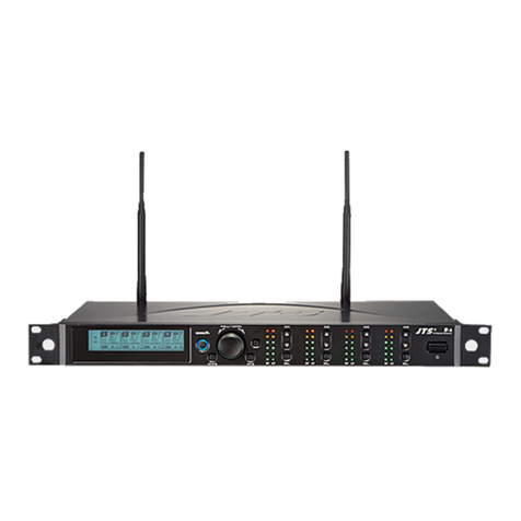
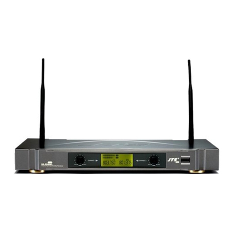
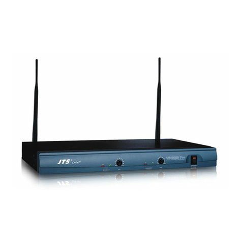
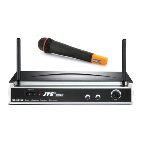
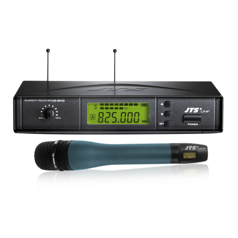
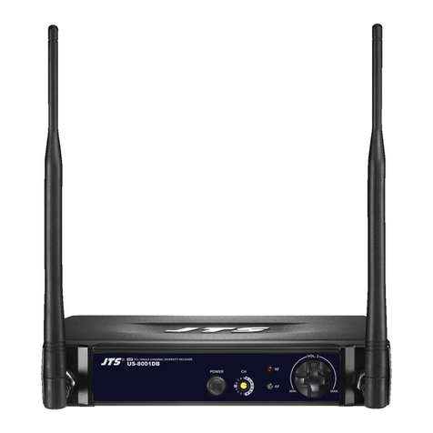
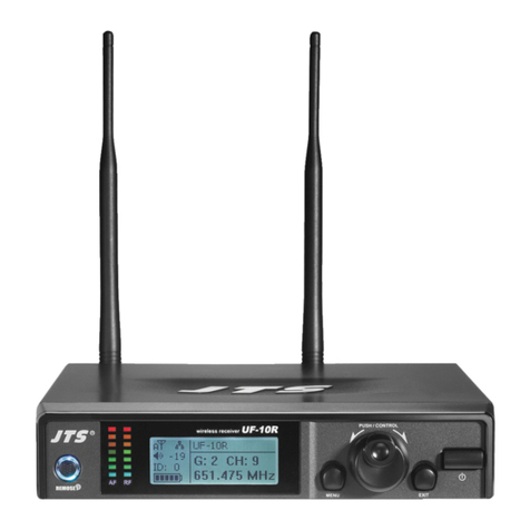
JTS RU-901G3 User manual

RU-901G3 /RU-G3TH /RU-G3TB
UHF PLL
UHF PLLTransmitter
VOL.
MIN. MAX.
DIVERSITY
RECEIVER
PROFESSIONAL CO., LTD
Instruction Manual
With JTS Ultrasonic Synchronizing Technology

One year product warranty
Warranty description
1. Be sure to put the warranty label indicating purchase date on the bottom of
equipment to ensure your interest in maintenance and service.
2. Product warranty, starting on the purchase date indicated on “warranty
label”, will last for one year; if the equipment does not have “warranty
label”, the warranty period is 15 months from the manufacturing date. If a
microphone is broken but not sent back with the equipment, the warranty
period is 15 months from the manufacturing date of the microphone.
3. Within the warranty period, if the equipment is broken under normal use as
instructed in manual, please contact the original selling store for repair.
4. When the product is returned for repair, to facilitate proper determination of
cause of malfunction and of whether repair fee is needed, please ship back
the equipment and microphone together.
5. Within the warranty period, our company provides repair service at no cost
except for the following conditions that parts and repair may be charged:
a.Damages due to natural disaster or irresistible outside forces.
b.Damages due to drop, water, moisture, corrosion, foreign objects, missing
components.
c.The warranty does not cover consumable parts. (such as microphone
capsule, ball grille etc.)
d.Those without “warranty label” on equipment or with “warranty label”
being damaged and failing to identify warranty period.
6. Please keep the warranty properly. No replacement will be made if the war-
ranty is missing.
Equipment
serial number
Contact
number
Address
Purchase date
Selling store
stamp Be sure to put store stamp and fill in purchase date for the warranty to be
effective!
Product Model
Customer
name

1. Notes for system operations
2. Features
3. Specications
3-1 UHF PLL single-channel True Diversity receiver// RU-901G3
3-2 UHF PLL hand-held transmitter // RU-G3TH
3-3 UHF PLL body-pack transmitter // RU-G3TB
3-4 Optional condenser microphone
4. Description of parts
4-1 UHF PLL single-channel True Diversity receiver // RU-901G3
4-2 UHF PLL hand-held transmitter // RU-G3TH
4-3 UHF PLL body-pack transmitter // RU-G3TB
4-4 Optional remote mute switch PT-RMS
4-5 Optional Condenser Microphone
4-6 Accessories
5.Connecting
5-1 How to connect the receiver// RU-901G3
5-2 Transmitter installation // RU-G3TH/G3TB
6. Instructions for use
6-1 How to use// RU-901G3
6-2 How to use// RU-G3TH/G3TB
6-3 Installation of Condenser Microphones
7. Notes for the product
1
1
2
2
3
4
4
7
7
9
11
12
12
16
17
17
18
19
19
23
25
27
INDEX

WIRELESS MICROPHONE SYSTEM
1
1. Notes for system operations
• Beforeconnectingthepower,checkthatthepowerrequirementshown
ontheunitisthesameasthepoweroutputontheadaptorsupplied.
• Donotleavetheunitatwherethehumidityandtemperaturearehigh.
• Dryyourhandsbeforeoperatingthesystem.
• Keeptheunitawayfromreandheatsource.
• Turnthevolumetominimumatboththemixerandamplierbefore
settingupthesystem.
2. Features
• 3rdgenerationTrueDiversitysystem
• Transmissionpowerselectablebetween'"High"and"Low"
• 6groupsareprovidedasdefault.Everygroupcontainsupto23default
channels.
• Thereareintotal1,441channelstochoosefrom.
• 36MHzbandwidth.
• Thepatentedultrasonicpairingforsynchronizedsettingofall
parameters
• Channelscan
• Adjustablereceivingsensitivity
• Automaticmicrophonepowero
• Chargingcontactready

2
3. Specications
3-1 UHF PLL single-channel True Diversity receiver // RU-901G3
FrequencyOscillation
Mode
Phase-lockedloop(PLL)
CarrierFrequencyRange 470~960MHz
RemosetFrequency Ultrasonic
Diversity Truediversity
Bandwidth 36MHz
Signal/NoiseRatio >105dB(A)
TotalHarmonicDistortion
(Thd)
<0.6%@1KHz
ReceivingSensitivity -95dBm,S/N>80dB
ImageRejectionRatio >80dB
FrequencyResponse 50Hz~18KHz±2dB
AntennaType 1/2λ BNCdetachable
AntennaBoosterPower DC12~15V/100mA
FunctionDisplayBy LCD
ContentsOfDisplay
Group,channel,frequency,batterylevel,antennaA/B,muting
,AFindication,RFindication,channelscanning,outputlevel
attenuation
ControlFunctions Power,group,channel,frequency,muting,buttonlock,volume,
outputattenuation(XLR),channelscan(on/o)
AudioFrequencyOutput
Level
ψ6.3PhoneJack:-10dBV
XLRJack:-4dBV(Line)、-24dBV(MIC)
AudioFrequencyOutput
Impedance
600Ω
Muting Noisemutingandtonecodelocking
OutputPort 1xbalancedXLRjack
1xunbalancedϕ6.3jack
PowerSupply 12~15VDC/500mA
Dimension(Mm) 212.3mm(W)x38.3mm(H)x144mm(L)

WIRELESS MICROPHONE SYSTEM
3
3-2 UHF PLL hand-held transmitter // RU-G3TH
FrequencyOscillationMode Phase-lockedloop(PLL)
CarrierWaveFrequencyRange 470~960MHz
RemosetFrequency Ultrasonic
RFPowerOutput 10mW/50mW(asperlocalregulations)
RFStability <±10KHz@Fc
ModulationFrequencyShift ±48KHz
HarmonicRadiation <-50dBc
Functions Mute,autoo,sensitivityadjustment,lowpower
indication
DisplayBy LCD+LED
Controls Power,mute,group,channel,frequency,sensitivity
adjustment,autoo,buttonlock
Battery AAalkalibatteryorMiNHrechargeablebatteryx2
Charging Yes
Dimension 51mm(W)x269mm(H)x26mm(L)

4
3-3 UHF PLL body-pack transmitter // RU-G3TB
3-4 Optional condenser microphone
Lavaliere microphone // CM-501 CM-201i CM-125i
FrequencyOscillation
Mode
Phase-lockedloop(PLL)
CarrierWaveFrequency
Range
470~960MHz
RemosetFrequency Ultrasonic
RFPowerOutput 10mW/50mW(asperlocalregulations)
RFStability <±10KHz@Fc
ModulationFrequency
Shift
±48KHz
HarmonicRadiation <-50dBc
Functions Mute,autoo,inputlevelattenuation,sensitivity
adjustment,lowpowerindication
DisplayBy LCD+LED
InputPort 4pinMiniXLR
Controls Power,mute,group,channel,frequency,sensitivity
adjustment,inputlevelattenuation,autoo
Battery AAalkalibatteryorMiNHrechargeablebatteryx2
Charging Yes
Dimension 62mm(W)x97mm(H)x20mm(L)
Model CM-501 CM-201i CM-125i
Connector 4-pinminiXLR 4-pinmini 4-pinminiXLR
FrequencyResponse 100~15,000Hz XLR60~15,000Hz 50~18,000Hz
PolarPattern Cardioid Omni-directivity
Sensitivity(at1000Hz) -60±3dB -60±3dB -53±3dB
Impedance 2.2KΩ 4.4KΩ
Max.SPLfor1%THD 130dB
Dimension(mm) Ø10.1mm(W)x
26.4mm(H)
Ø5mm(W)x
9mm(H)
Ø4mm(W)x
11mm(H)
NetWeight 21.5g 20.7g 7g(cablenotincluded)

WIRELESS MICROPHONE SYSTEM
5
Headset microphone
Model CM-214i CM-214Ui CM-214ULi
Connector
801C4
(4PMiniXLR)
4PMiniXLR 801C3(3PMiniXLR)
801C4(4PMiniXLR)
801CS(3.5stereoplug)
Option
Connector
801C3(3PMiniXLR)
801CS(3.5stereo
plug)
801CR
801CR
FrequencyResponse 60~15,000Hz 30~18,000Hz 100~18,000Hz
PolarPattern Omni-directional Cardioid
Sensitivity(at1000Hz) -60±3dB -68±3dB -65±3dB
Impedance 1.8kΩ 680Ω 1.8kΩ
Max.SPLfor1%THD 130dB 120dB
Dimension(mm)
125mm(W)x
134mm(H)x
157mm(D)
205mm(W)x
134mm(H)x
157mm(D)
125mm(W)x
134mm(H)x
157mm(D)
NetWeight 32.9g 38.4g 18g(cableexcluded)
Model CM-235i CX-504
Connector 801C4(4PMiniXLR) 4PMiniXLR
FrequencyResponse 50~18,000Hz 30~18,000Hz
PolarPattern Omni-directional Cardioid
Sensitivity(at1000Hz) -53±3dB -68±3dB
Impedance 1.8kΩ 680Ω
Max.SPLfor1%THD 130dB 130dB
Dimension(mm)
155mm(W)x
134mm(H)x
157mm(D)
285mm(W)x
55mm(H)x
111.3mm(D)
NetWeight 17g(cableexcluded) 56.3g

6
Compatible Instrument Microphone // CX-500 CX-500F CX-520
CX-508W CX-516W
Ear-hook microphone // CM-801 CM-804i CM-8015 CM-825i
ModelNo CX-500 CX-500F CX-520
Connector 4PMiniXLR 4PMiniXLR 4PMiniXLR
FrequencyResponse 20~20,000Hz 20~20,000Hz 50~16,500Hz
PolarPattern Omni-directional Omni-directional Supercardioid
Sensitivity(at1000Hz) -58±3dB -58±3dB -78±3dB
Impedance 1.5kΩ 1.5kΩ 600Ω
Max.SPLfor1%THD 130dB 130dB 148dB
GoodFor Violin Flutes Harmonica
ModelNo CX-508W CX-516W
Connector 4PMiniXLR 4PMiniXLR
FrequencyResponse 50~18,000Hz 30~18,000Hz
PolarPattern Cardioid Cardioid
Sensitivity(at1000Hz) -67±3dB -67±3dB
Impedance 220Ω 220Ω
Max.SPLfor1%THD 130dB 130dB
GoodFor Winds Accordion
ModelNo CM-801/CM-804i CM-8015/CM-825i
Connector 801C4(4PMiniXLR) 801C4(4PMiniXLR)
OptionConnector
801C3(3PMiniXLR)
801CS(3.5stereoplug)
801CR
801C3(3PMiniXLR)
801CS(3.5stereoplug)
801CR
FrequencyResponse 60~15,000Hz 50~18,000Hz
PolarPattern Omni-directional Omni-directional
Sensitivity(at1000Hz) -64±3dB -53±3dB
Impedance 1.8kΩ 1.8kΩ
Max.SPLfor1%THD 130dB 130dB

WIRELESS MICROPHONE SYSTEM
7
4. Description of parts
4-1 UHF PLL single-channel diversity receiver( True Diversity ) // RU-901G3
Frontpanel
Power On/O switch:Pressoncetoturnonthepower,pressandholdfor2
secondstoturnof.
SET:thisisforfunctionsettings.Pushandholdfor2secondstoenterthesetting
mode.Push“SET”repeatedlytosearchforthefunctionyouwishtoset.
▲/▼Inthesettingmode,push▲/▼tochangethefunctionparameter
Inthenon-settingmode:push▲/▼toadjustvolume
LCD display
AF signal level
RF signal level
Volume control
Remoset u :thisallowsusertosynchronizethetransmitteraftermodifyinga
parameter.Push“”tosynchronizethesettingstothetransmitter.
Remoset indicator : thisshowsthecurrentpairingstatus.Itashesrapidly
whendataisbeingtransmittedandtheashingstopswhenthesynchronization
iscompleted.However,theashingslowsdownifsynchronizationfailsaftera
periodoftimeofpairingattempt.
Ultrasonic transmission unit: ittransmitsdigitalpairingdataatultrasonicfre-
quency.Whensetting,directtheultrasonicreceivingelementofthemicrophone
totheultrasonictransmittingunitofthereceivers.Theeectiverangeis30ºon
bothsideswiththeoptimizeddistanceat30cm.
Antenna
1
4
2
5
3
6
7
11
10
8
9
VOL.
MIN. MAX.
DIVERSITY RECEIVER
1
3
2
11
10
4
8
5
69
7

8
Rearpanel
DC power socket: for12~15VDC/500mApowersupply
Female BNC antenna port:
the50ΩBNCantennaisconnectedhere.Italso
providesaboosterpowerof12~15DC/100mAforanexternalantennabooster.
6.3mm phone jack:unbalancedaudiooutputjack
3P XLR male:balancedaudiooutputjack
23
21
12
22
22 21 212320
15
16
18
14
17
13
: AntennaA/B
: Transmitterbatterylevel
: Group/channel
: Key Lock
: Receivermute
: Outputattenuation
:Squelchlevel
: Frequency
: 數位音碼
Inthenon-settingmode,theLCDlookslike:
19
20
/
13
16
1814 17
19 15 12

WIRELESS MICROPHONE SYSTEM
9
4-2 UHF PLL hand-held transmitter // RU-G3TH
1
4
2
5
3
6
7
8
9
10
9
6
5
1
2
7
8
3
10
4
Power: pushtoturnthetransmitteron.Whenthetransmitterison,pushand
holdfor2secondstoturnito.
Mute: whilethetransmitterison,switchMuteuptotalkanddowntomute.If
thetransmitteriso,switchtheMuteuptoturntheuniton.Thetransmitter
turnsitselfoautomaticallyafter1,10or30minutesofmutingdependingon
setting.
Ultrasonic receiving unit:itreceivespairingsignalsfromtheultrasonic
transmissionunitatthereceiverend.
Battery holder:itholdsUM3,AA1.5Vbatteryorrechargeablebatteryx2.
LED indicator:itshowsthetransmitter’sstatus,includingbatterylevel,mute
andpairingindication.
LCD display:itshowstheparametersettingsinthetransmitter.
SET:itallowsparametersettings,includingfrequency,group,channel,sensitiv-
ity,transmissionpower,autoocountdownandmachinecode.
▲/▼:theseareusedwith“SET”tochangetheparametersettings.
:pushandholdthe“LOCK”buttonfor2secondstolockthebuttons.Pushand
holdagainfor2secondstounlock.
Charging contact:ifrechargeablebatteriesareused,thismicrophonecanbe
rechargedwithanoptionalcharger.

10
LED
Green Battery>2V
Flashinggreen Microphonemute
Red Battery ≤2V
Alternatingredandgreen Microphonemute(andbatterylow)
Blue Pairingsuccessful
Flashingblue Datareceivingerror
Indicators
Battery charging is supported. The transmitter turns off automatically when
charging.
When battery is < 1.8V, the transmitter will turn off automatically.
If the microphone is turned off with the mute switch on mute, just slide the
switch up to turn the microphone on.
Others

WIRELESS MICROPHONE SYSTEM
11
4-3 UHF PLL body-pack transmitter // RU-G3TB
LCD display
Ultrasonic receiving unit:itreceivesthepairingsignalsfromthe
ultrasonictransmissionunitatthereceiverend.
REMOSET indicator:
Blue:Pairingsuccessful
Flashingblue:Datereceivingerror
Power:
(1)On:pushthepowerbutton
O:pushandholdthepowerbuttonfor2secondstillthedisplay
shows“PowerO.”
(2)ExitSettingMenu:whenintheSettingMenu,pushthepowerbutton
toreturntothemainscreen.
▲/▼:theseareusedwith“SET”tochangetheparametersettings.
SET:tosetandsave
Mute Switch / LED Indicator :
(1)Showgreenlightwhenpowerison.
(2)Showredlightwhenbatterylevelistoolow.
(3)Flashredlightwhenswitchto''MUTE''functiontomutethetransmitter.
(4)Flashredlightandgreenlightwhenmutefunctionisonandbattery
levelistoolow.
Battery tray
UHF PLLTransmitter
1
2
3
4
8
5
6
7
1
4
2
5
3
6
7
8

12
Clip
4PinMiniXLR
3PinMiniXLR
3.5StereoPlug
4PinHiroseconnecter
Windscreen
1
3
4
5
6
2
4-5 Optional Condenser Microphone
Lavaliere Microphone // CM-501 CM-201i CM-125i
CM-501 CM-201i CM-125i
666
1
1 1
2 3 4 5
Option
Option
Option
4-4 Optional remote mute switch PT-RMS
PT-RMS

WIRELESS MICROPHONE SYSTEM
13
Gooseneck
Adjustableheadband
Headband
4PinMiniXLR
3PinMiniXLR
3.5StereoPlug
4PinHiroseconnecter
Windscreen
Headset Microphone // CM-214i / CM-214Ui / CM-214ULi / CM-235i /
CX-504
CM-214i CM-214Ui
CM-235i
CM-214ULi
CX-504
2
4
5
6
7
8
1
3
2 2 2
8 8 8
1 1 1
2 3
8
8
1
1
Standard :
4 Pin Mini XLR
3 Pin Mini XLR
3.5 Stereo Plug
5 64 7
Option
Option
Option

14
Ear-hook Microphone // CM-801 / CM-804i / CM-8015 / CM-825i
Boom
AdjustableHeadband
Adjustableearhook
DetchableCable
CableClip
Windscreen
4PinMiniXLR
3PinMiniXLR
3.5StereoPlug
4PinHiroseconnecter
6
8
7
9
10
3
5
4
1
2
2
6
3
5
4
1
63
5
4
1
2
6
3
5
4
1
63
5
4
1
CM-801
CM-804i
CM-8015
CM-825i
8 97 10
Option
Option
Option

WIRELESS MICROPHONE SYSTEM
15
Compatible Instrument Microphone // CX-500 / CX-500F / CX-520 /
CX-508W / CX-516W
Gooseneck
Clip
Bracket
VolumeControl
Windscreen
4PinMiniXLR
1
2
3
4
CX-508W CX-516W
1 1
2
5
6
6
3
5
5
5
5CX-500F
CX-500
1
2
CX-520
4

16
4-6 Accessories
1
1
3
3
2
2
4
5
4
A
B C
5
6
6
7
8
7 8
AC/DCadaptor
SwitchingPowerSupply(100V~240V,50~60Hz)
LinearPowerSupply(220V,50Hz)
LinearPowerSupply(220V,60Hz)
Screwdriver
DR-900DualRackAdaptor
RM-901RackMountKit
RP-900PanelCover
AFoutputcable(withΦ6.3plugatbothends)
GC-80/GC-100GuitarCable
GC-80L/GC-100LGuitarCable
Option
Option
Option
Option
Option
Option
Option
A
B
C

WIRELESS MICROPHONE SYSTEM
17
5. Preparing Procedures
5-1 How to connect the receiver// RU-901G3
(1) Poweroutputconnector
PluginoneendofAC/DCadaptorcabletoDCinputsocketintherearpanelof
receiver,andpluganotherendintoanACoutlet.(Step1)
(2) AudioOutputConnector
ConnectoneendoftheAFoutputcabletotheAFoutputsocketintherear
panel,thenpluganotherendtothe“MICIN”inputsocketofamixeroramplier.
(Step2)
ReceiverequippedwithbalancedXLRoutputandUnbalanced
Ø
6.3mmoutput,
choosetheproperwayforuse.
MIXER
AC/DCADAPTOR
ACPOWERSOCKET
AUDIOOUTPUT
DCINPUT
2
1
This manual suits for next models
2
Table of contents
Other JTS Microphone System manuals