1. Important Caution
2. Features
Always makes all connections before plugging the unit into an AC power outlet.•
Do not leave the device in a place neither with high temperature nor high humidity.•
Always do not handle the power cord with wet hands!•
Keep the devices away from re and heat sources.•
Makes sure receiver/transmier are in the same preset channel or frequency.•
3. Specication
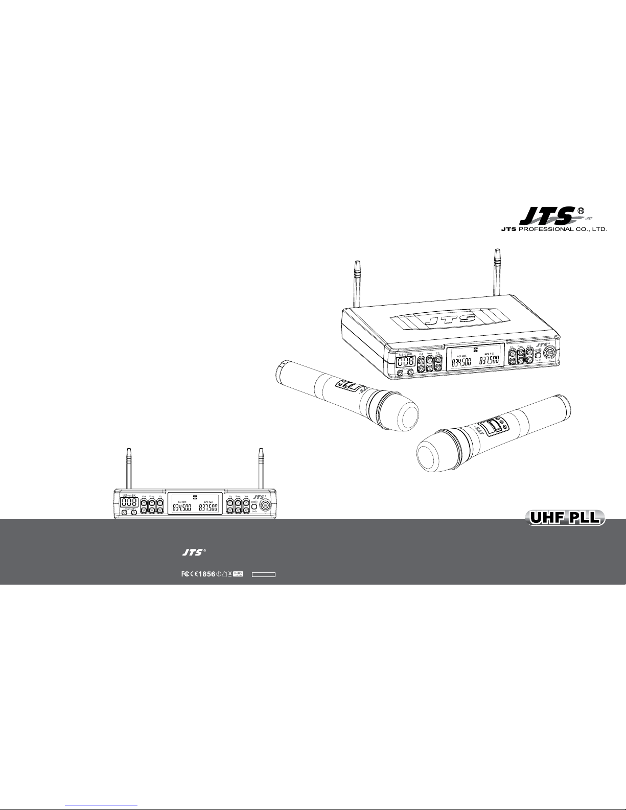
3-1 UHF PLL Dual Channel Diversity Receiver // US-936K
3-2 UHF PLL Handheld Transmitter // Mh-936K
Frequency Preparation......
Carrier Frequency Range
S/N Ratio...................................
T.H.D..............................................
Display...........................................
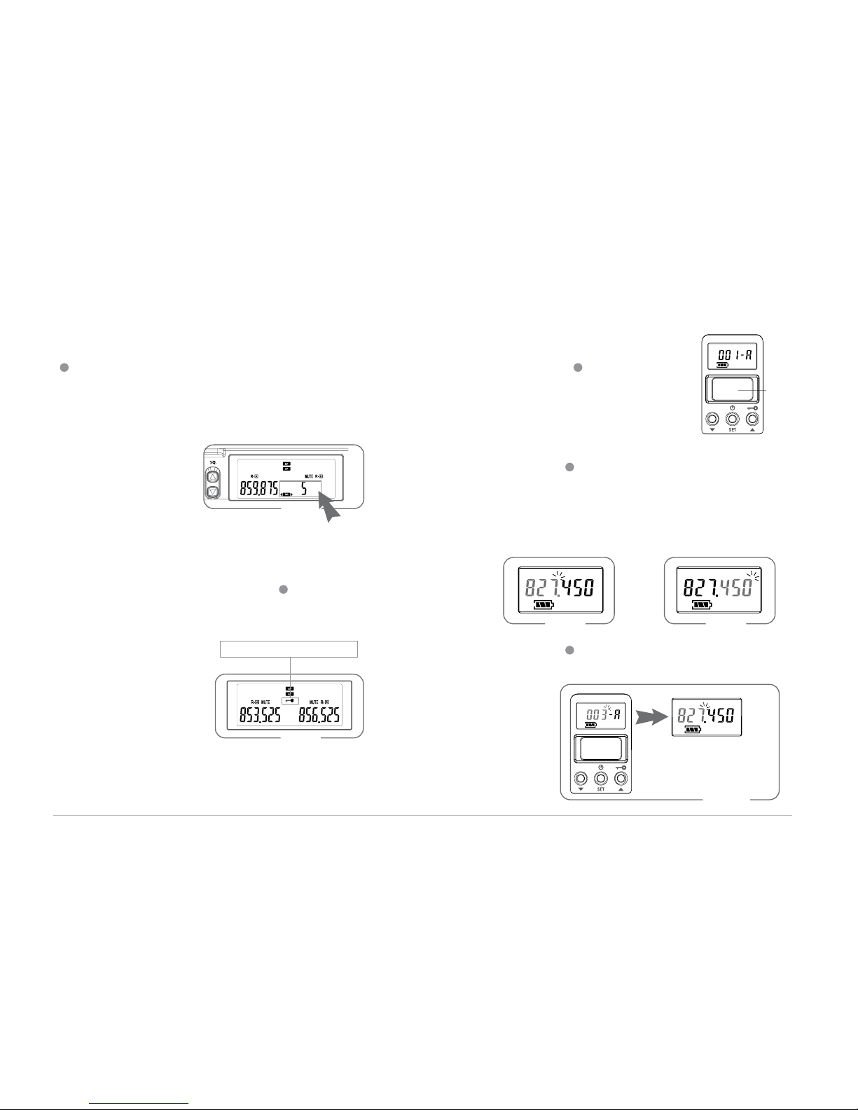
Display Contents...................
Controls.......................................
Audio Output Level.............
AF Output Impedance.......
Operation Voltage.................
Output Connector................
Dimension(m/m).................
PLL Synthesized Control
36MHz within 502~960 MHz
>105dB
<0.6%@1KHz
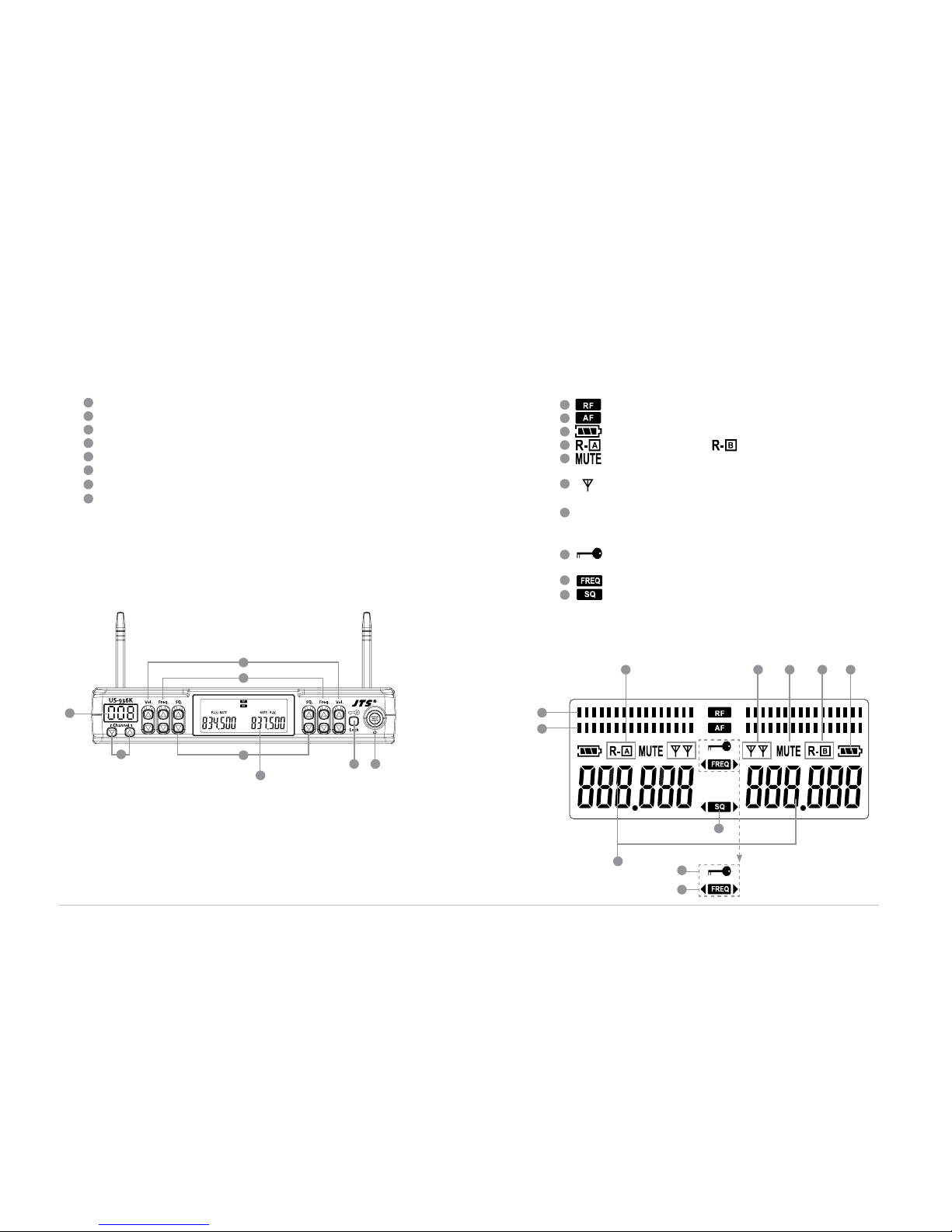
LCD/LED
Channel, Antenna A/B, Mute Display, RF/AF Level Meter,
Low baery, SQ
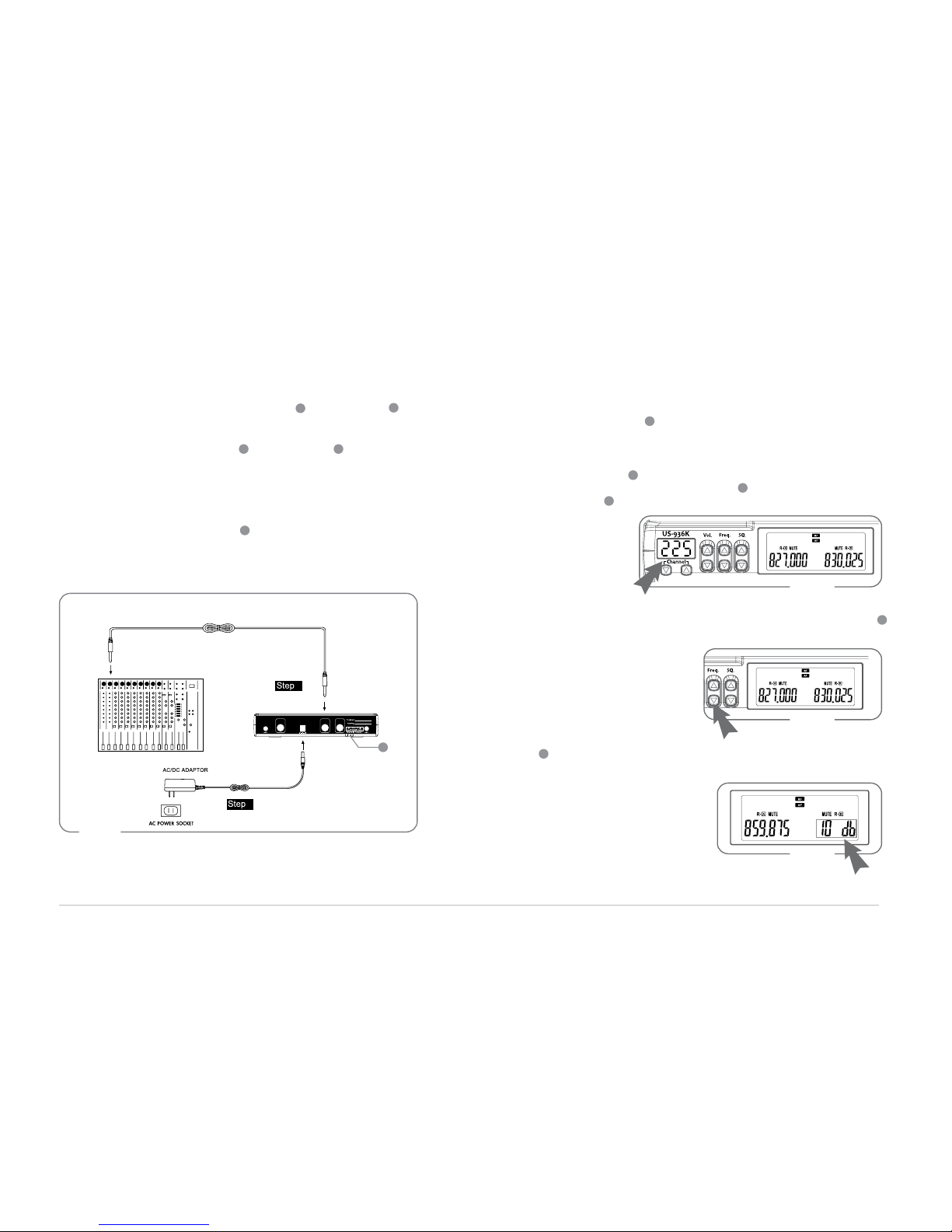
Power On/O, Frequency Up/Down, Volume, SQ,
Preeset channel 001~225
-12dB
600Ω
12-18 VDC, 500mA
3 unbalanced Ø6.3mm phone jack
210mm(W) * 40mm(H) * 172mm(D)
Frequency Preparation...........
Carrier Frequency Range.....
RF Outputs....................................
Stability...............................................
Frequency Deviation...............
LCD Display..................................
Controls............................................
Spurious Emissions...................
Audio Frequency Response
Baery.................................................
PLL Synthesized Control
502~960 MHz
Lo:3mW , Hi:10mW
(Depend on Local Regulation)
±10KHz
±48KHz
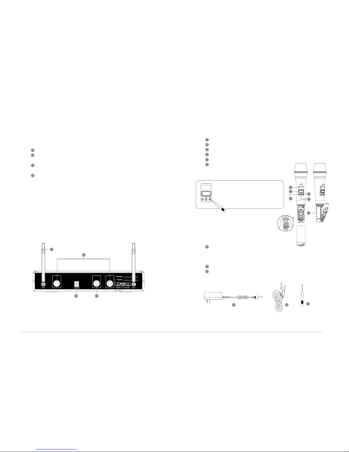
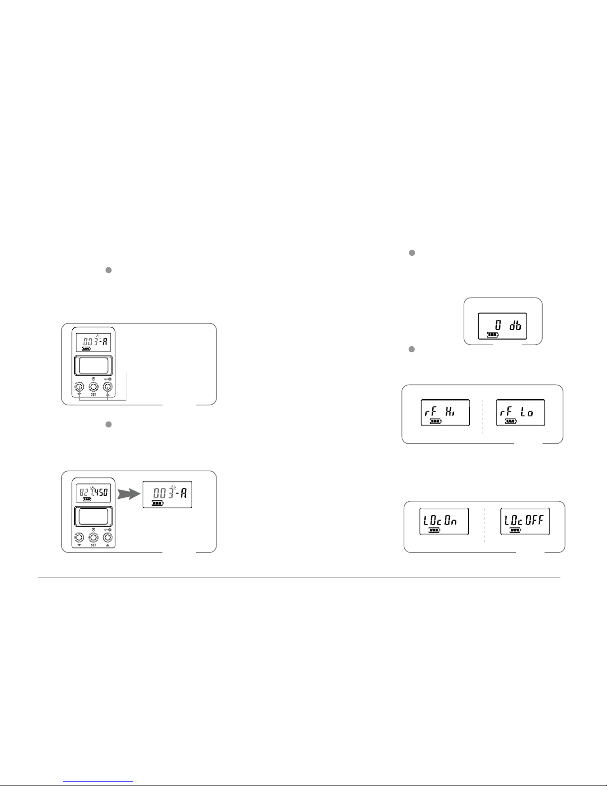
Preset channel, Baery Fuel Gauge, Frequency
Power On/O, Frequency Up/Down,
Lock-on Mode,Preset channel,A or B channel
select, RF outputs adjust, Gain control
<-50 dBC
50~16,000 Hz
UM3, AA 1.5V*2
At super-wide band of 36 MHz, specially intended for exquisite KTV rooms and classrooms
•
Operation functions designed to be user-friendly•
Preset with 225 pairs of channels•
Unprecedented 001-225 coded reception/transmission channels•
Dual channel (receiving) set with one key•
All-new D-36K highly sensitivity and anti-feedback capsule•
Adjustable squelch level at front panel•