JUKI MF-7900 Series User manual

ENGLISH
MF-7900
INSTRUCTION MANUAL

i
CONTENTS
!. SPECIFICATIONS ..........................................................................................................1
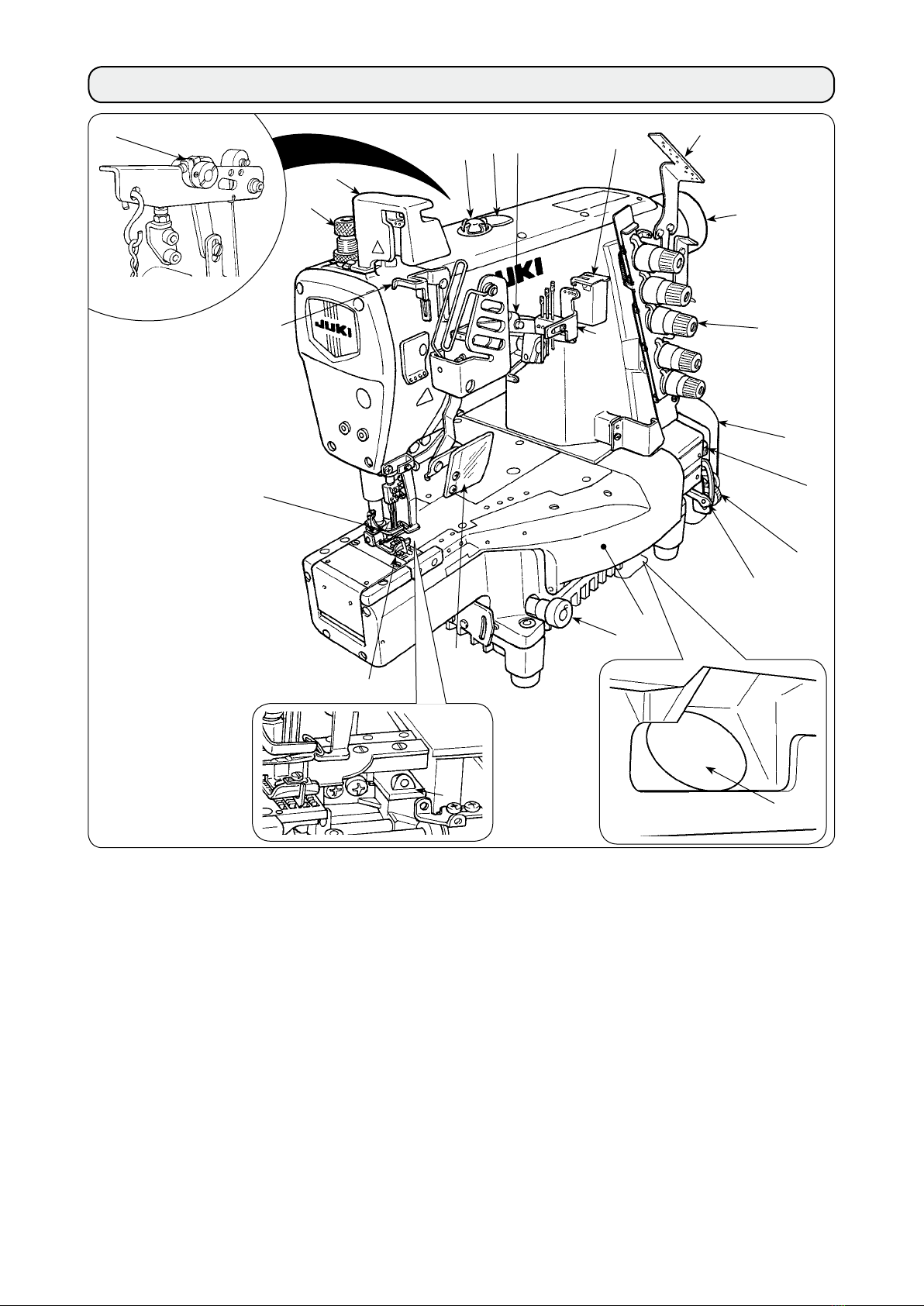
@. CONFIGURATION OF THE MACHINE COMPONENTS ...............................................2
#. INSTALLATION ..............................................................................................................3
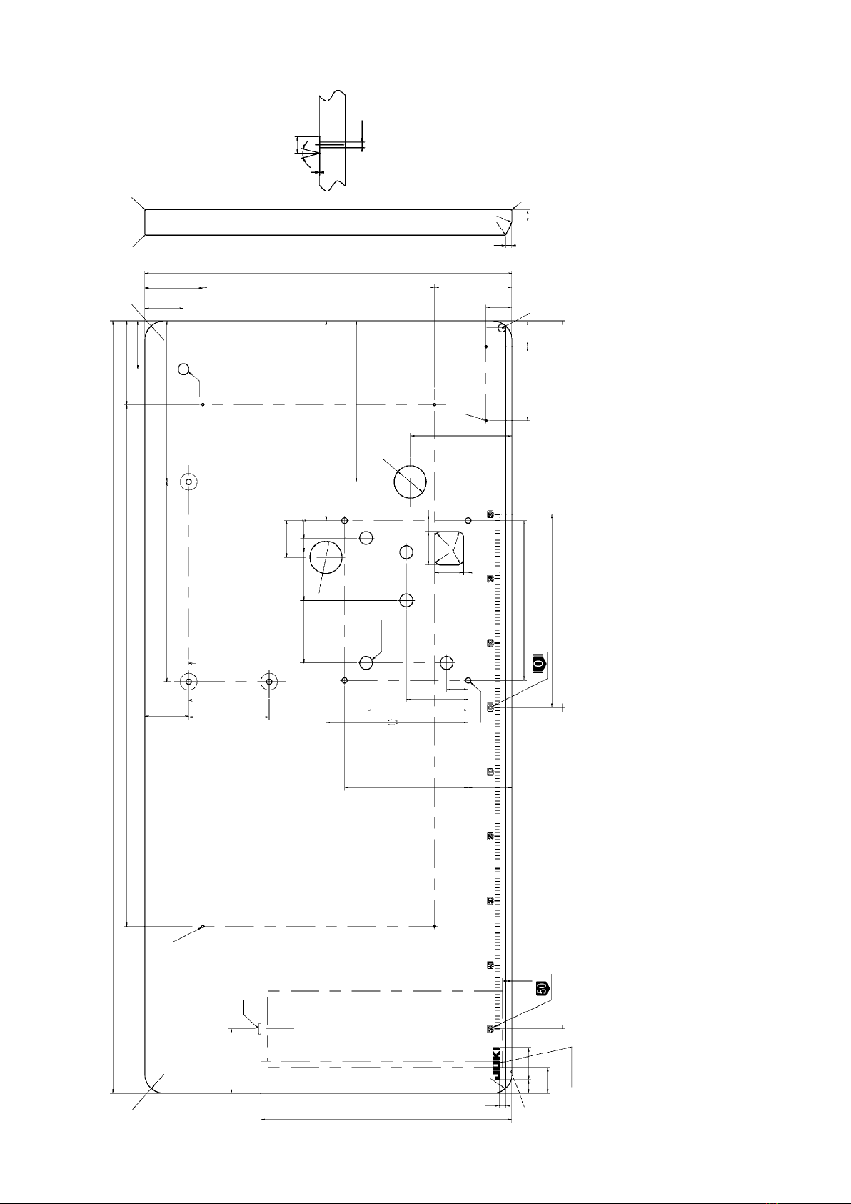
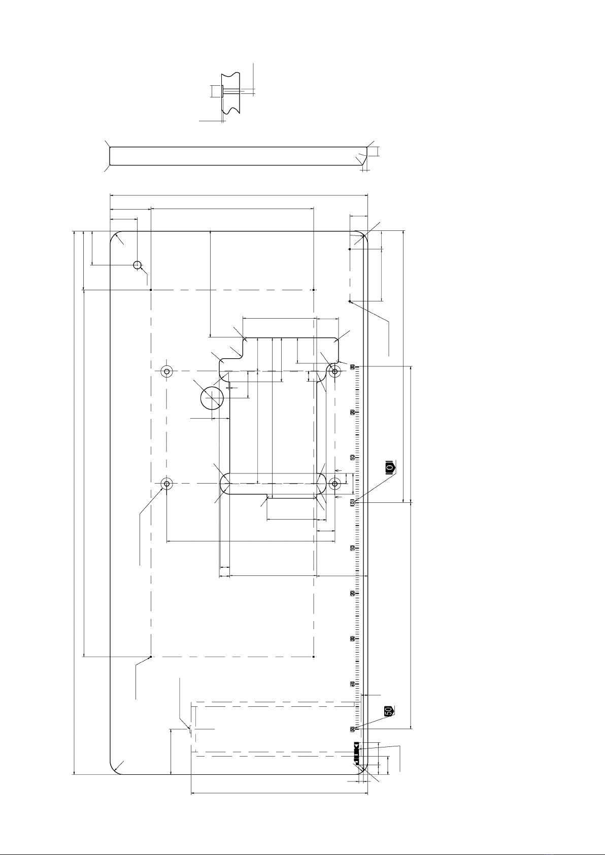
1. Installing the machine head onto the table ........................................................................... 3
2. Selecting the motor pulley and the belt................................................................................. 9
3. Installing the motor.................................................................................................................. 9
4. Setting the belt ........................................................................................................................ 9
5. Installing the belt cover......................................................................................................... 10
6. Installing the chain ................................................................................................................ 10
7. Installing the thread guide .................................................................................................... 10
8. Installing the needle bar thread take-up cover ................................................................... 11
$. LUBRICATION AND OILING .......................................................................................11
1. Lubricating oil ........................................................................................................................ 11
2. Oiling....................................................................................................................................... 11
3. Silicon oil lubricating unit..................................................................................................... 12
%. OPERATION.................................................................................................................12
1. Needle ..................................................................................................................................... 12
2. Attaching the needle.............................................................................................................. 12
3. Threading the machine head ................................................................................................ 13
(1) Standard threading .................................................................................................................. 13
4. Adjusting the stitch length.................................................................................................... 14
5. Adjusting the differential feed ratio ..................................................................................... 14
6.
Adjusting the presser foot pressure......................................................................................... 15
7. Adjusting the thread tension ................................................................................................ 15
^.
ADJUSTING THE SEWING MACHINE.......................................................................................16
1. Adjusting the silicon container thread guide...................................................................... 16
2. Adjusting the needle bar thread take-up thread receiver .................................................. 16
3. Adjusting the rocking thread take-up .................................................................................. 17
4. Adjusting the spreader thread guide ................................................................................... 17
5. Adjusting the looper thread cam thread guide and the looper thread cam ..................... 17
6. Adjusting the looper .............................................................................................................. 18
7. Adjusting the height of the needle ....................................................................................... 18
8.
Adjusting the rear needle guard.................................................................................................................19
9. Relation between the rocking thread take-up timing and the needle thread loop ..............19
(1) Adjustment by the crank ......................................................................................................... 19
(2) Adjustment by the eccentric cam ........................................................................................... 20
10. Adjusting the height of the feed dog ................................................................................... 21
11. Installing position of the spreader ....................................................................................... 21
12. Adjusting the spreader thread guide and the needle clamp thread guide....................... 22
13. Adjusting the front needle guard ......................................................................................... 22
14. Adjusting the presser foot lift............................................................................................... 23
15. Adjusting the micro-lifter ...................................................................................................... 23
16. Adjusting the feed locus ....................................................................................................... 24
(1) Retarding the feed driving motion.......................................................................................... 24
(2) Retarding the feed rocking motion......................................................................................... 25
17. Adjustment value of balloon................................................................................................. 26
&. MAINTENANCE ...........................................................................................................28
1. Cleaning the sewing machine............................................................................................... 28
2. Replacing the lubricating oil ................................................................................................ 28
3. Inspectingandreplacingtheoillter .................................................................................. 28

– 1 –
!. SPECIFICATIONS
Model name High-speed, cylinder-bed coverstitch machine
Model MF-7900 series
Stitch type ISO standard 406, 407, 602, and 605
Example of application Hemming and covering for knits and general knitted fabrics
Sewing speed
Max. 6,500 sti/min (at the time of intermittent operation) V-belt type
6,000 sti/min (at the time of intermittent operation) Direct-drive type
Speed of stitch at the delivery. 4,500 sti/min (at the time of intermittent operation)
Needle gauge 3-needle ... 5.6 mm and 6.4 mm
2-needle ... 3.2 mm, 4.0 mm and 4.8 mm
Differential feed ratio
1 : 0.9 to 1 : 1.8 (stitch length : less than 2.5 mm)
(1:0.6 to 1:1.1, when the differential link hinge screw is changed)
Micro-differential feed adjustment mechanism is provided. (Micro-adjustment)
Stitch length 0.9 mm to 3.6 mm (can be adjusted up to 4.5 mm)
Needle UY128GAS #9S to #12S (standard #10S)
Needle bar stroke 31mm (33 mm, when the eccentric pin is changed)
Dimensions (Height) 450 x (Width) 468 x (Length) 264
Weight 42 kg
Lift of presser foot 8 mm (needle gauge : 5.6 mm without top covering), and 5 mm (with top covering)
Micro-lifter mechanism is provided.
Feed adjustment
method
Main feed ... dial type stitch pitch adjustment method
Differential feed ... lever adjustment method
(micro-adjustment mechanism is provided.)
Looper mechanism Spherical rod drive method
Lubricating system Forced lubrication method by gear pump
Lubricating oil JUKI GENUINE OIL 18
Oil reservoir capacity Oil gauge lower line : 600 cc to upper line : 900 cc
Installation Table-xed type, Semi-submerged type
Noise
- Equivalent continuous emission sound pressure level (LpA) at the workstation :
A-weighted value of 79.5 dB; (Includes KpA = 2.5 dB); according to ISO 10821- C.6.2
-ISO 11204 GR2 at 4,500 sti/min.

– 2 –
@. CONFIGURATION OF THE MACHINE COMPONENTS
1Presser spring regulator !4 Needle tip silicon oil lubricating unit
2Needle bar thread take-up cover !5 Differential lock nut
3Oil circulation inspection windows !6 Micro-adjustment knob
4Oil hole cap !7 Finger guard
5Micro-lifter !8 Rocking thread take-up
6Needle thread silicon oil lubricating unit !9 Front cover
7Thread guide No. 1 @0
Needle bar thread take-up thread
receiver
8Upper pulley @1 Silicon container thread guide
9Thread tension nut @2 Belt cover
!0 Oil gauge @3 Differential feed regulating lever
!1 Feed regulating knob
!2 Eye guard cover
!3 Throat plate
1
2
346
8
9
!1
!3
!5
!6
!7
!8
@2
!9
@0
@3
@1
5
!2
7
!4 !0

– 3 –
#. INSTALLATION
Attach the pins and the rubber cushions as shown in
the illustration and properly install the sewing machine.
1
Rubber cushion (Black) x 3
2Washer
3Spring washer
4Nut
5Pin
6
Rubber cushion (Gray) x 1
Attach the supporting board and the rubber seats as
shown in the illustration and properly install the sewing
machine.
1Bolt
2Spacer
3Washer
4Spring washer
5Nut
6Supporting board
7Spring pin
8Rubber cushion (Black) x 3
9Rubber cushion (Gray) x 1
Semi-submerged type
1. Installing the machine head onto the table
WARNING :
Do not insert the power plug of the motor into the receptacle until all works have been completed. There
is a danger of injury by being caught in the machine.
WARNING :
The weight of the sewing machine is more than 42 kg. Be sure to perform the work with two persons or
more in case of unpacking, transportation or installation.
1
5
2
3
4
1
2
3
4
5
6
7
8
6
9
■Installing the rubber cushion
Install the gray dust-proof rubber to section A only.
Part No. Part name Q'ty
140072505 Dust-proof rubber (Gray) 1
213155403 Dust-proof rubber (Black) 3
A
1
2
2
[For the V-belt type]

– 4 –
[For the direct-drive type]
Attach the pins and the rubber cushions as shown in
the illustration and properly install the sewing machine.
1
Rubber cushion (Black) x 2
2Washer
3Spring washer
4Nut
5Pin
6
Rubber cushion (Gray) x 2
Attach the supporting board and the rubber seats as
shown in the illustration and properly install the sewing
machine.
1Bolt
2Spacer
3Washer
4Spring washer
5Nut
6Supporting board
7Spring pin
8Rubber cushion (Black) x 2
9Rubber cushion (Gray) x 2
Semi-submerged type
6
5
2
3
4
1
2
3
4
5
6
7
9
6
9
■Installing the rubber cushion
Install the gray dust-proof rubber to section A only.
Part No. Part name Q'ty
140072505 Dust-proof rubber (Gray) 2
213155403 Dust-proof rubber (Black) 2
A
12
21
1
8

– 5 –
1 DRAWING OF TABLE (TABLE-FIXED TYPE) V-BELT TYPE
A4- ø 3.4 on the bottom surface, depth 20 (Drill a hole at the time of set-up.)
BDrilled hole 17
C2- ø 3.4 on the bottom surface, depth 10 (Drill a hole at the time of set-up.)
98
Z - Z
130
810
159 ± 1 74 ± 1
75
R30
57
239 ± 1
52 17
115 40
ø 26
ø 8.5
10
360
570
60
(90)
B
A
66 ± 1
33
YY
R10
R10
387
R10
R10
45
Z
Z
R10
40
R30
192 ± 1
27
R10
R10
1
120
300
330
152
115
R10
R10
49
124
ø 50
221
R10
R10
R10
34
55
71
R10
R10
7
248 ± 1
68
221
158.5
96
33.5
C
R2
20
R2
R2
10
R2
R2
Y - Y (3 locations)

– 6 –
2 DRAWING OF TABLE (TABLE-FIXED TYPE) DIRECT-DRIVE TYPE
A4- ø 3.4 on the bottom surface, depth 20 (Drill a hole at the time of set-up.)
BDrilled hole 17
C2- ø 3.4 on the bottom surface, depth 10 (Drill a hole at the time of set-up.)
DInstalling position of drawer stopper (on the reverse side)
EJUKI logotype
1200
130
810
ø26
250310
100
57
248 ± 1
17
300
600500
40
21 50 115 40
570
360120 (90)
60
158
250
310
27
49
124
221
125 68
192 ± 1
221
158.5
96
33.5
68
52
457
10
390
15
40
ø8.5
1
30º
75
R30
R30
R30
R6
R30
R6
ø50
ø50
YY
A
B
C
D
R10
R10
R10
R10
E
R2
20
R2
R2
10
R2
R2
Y - Y (3 locations)

– 7 –
3 DRAWING OF TABLE (SEMI-SUBMERGED TYPE) V-BELT TYPE
A4 - ø 3.4 on the bottom surface, depth 20 (Drill a hole at the time of set-up.)
BInstalling position of drawer stopper (on the reverse side)
CDrilled hole 17
D2 - ø 3.4 on the bottom surface, depth 10 (Drill a hole at the time of set-up.)
EJUKI logotype
F4 - 10.5 hole, 26 hole facing depth 3.5
R2
20
R2
R2
10
R2
R2
1200
130
810
159 ± 1
100
366.5
248 ± 1
23
300
600
500
40
21 50 115 40
570
360 90
60
48
66 223.5 ± 1
113 ± 1
40
110
23
59
1
10
390
15
40
75
R30
R30
R30
R6
R30
R6
ø50
YY
A
C
B
R10
R10
R21
R10
E
D
F
66 ± 1
33
89.5 ± 1
303
333
R10
X
X
86.5
109.4
68
(2)
R18
R5
R10
R21
R10
ZZ
432
192 ± 1
21
272 ± 1
21
23
46
R21
R5
R5
R21
R21
10
X-X
Z-Z (4 locations)
ø26
ø8.5
1
30º
(3.5)
(ø26)
(ø10.5)
Y-Y (3 locations)

– 8 –
4 DRAWING OF TABLE (SEMI-SUBMERGED TYPE) DIRECT-DRIVE TYPE
A4 - ø 3.4 on the bottom surface, depth 20 (Drill a hole at the time of set-up.)
BInstalling position of drawer stopper (on the reverse side)
CDrilled hole 17
D2 - ø 3.4 on the bottom surface, depth 10 (Drill a hole at the time of set-up.)
EJUKI logotype
F4 - 10.5 hole, 26 hole facing depth 3.5
R2
20
R2
R2
10
R2
R2
1200
130
810
100
354.5
248 ± 1
23
300
600
500
40
21 50 115 40
570
360 90
60
48
235.5 ± 1
113 ± 1
40
110
23
59
10
390
15
40
75
R30
R30
R30
R6
R30
R6
ø50
A
C
B
R21
E
D
F
163
74.5
97.4
56
(2)
R18
R5
R10
R21
R10
ZZ
192 ± 1
21
372 ± 1
21
23
46
R21
R5
R5
R21
R21
Z-Z (4 locations)
(3.5)
(ø26)
(ø10.5)
R21
R10
R10
39

– 9 –
2. Selecting the motor pulley and the belt
3. Installing the motor
M o t o r
pulley
5.5 mm
10 mm
M type V belt
Use a clutch motor of 3-phase, 2-pole, 400 W (1/2HP).
Use the M type V belt.
1) The motor pulley shifts to the left-hand side when
depressing the pedal. At this time, install the motor
so that the centers of motor pulley and lower pulley
align with each other.
* For the installing procedure of the motor pulley, refer
to the Instruction Manual for motor.
Lower
pulley
2) Install the motor so that the pulley rotates clockwise.
If the machine pulley rotates in the reverse
direction, nomal lubrication cannot be
performed. As a result, machine trouble will
be caused.
4. Setting the belt
1) Fit belt 1to lower pulley 2.
2) Turning upper pulley 3, set the other side of the belt
to motor pulley 4.
3) Adjust the belt tension so that the belt sags 15 to 20
mm when the center of the belt is pressed with an
approximate 10N (1.02 kgf) load.
4) Securely x the belt with lock nut 5when the belt
has been set.
the sewing machine is operated, check again
the belt tension.
1
3
4
5
2
15 to 20mm
* The table shows the numbers when a 3-phase
2-pole 400 W clutch motor (1 / 2 HP) is used.
* The commercially-available motor pulley near to
the counted value is designated since the outside
diameter of the commercially-available motor pulley
counts by 5 mm.
Use a motor pulley which is adaptable to this
machine and machine trouble will be caused
unless a motor pulley which is adaptable to
this sewing machine is used.
When you use a new sewing machine, use
the machine at a speed of 4,500 sti/min or
one month). A good result can be obtained in
terms of the durability.
Motor pulley and belt
50Hz 60Hz
Speed of
stitch (sti/min)
Pulley size Belt size Pulley size Belt size
4,500 ø 100 M-39 ø 85 M-38
4,800 ø 110 M-40 ø 90 M-38
5,000 ø 115 M-40 ø 95 M-39
5,500 ø 125 M-41 ø 105 M-39
5,800 ø 135 M-42 ø 110 M-40
6,000 ø 140 M-42 ø 115 M-40
6,200 ø 145 M-43 ø 120 M-41
6,500 ø 150 M-43 ø 125 M-41
WARNING :
When replacing the belt, be sure to turn OFF the power to the motor and ascertain that the motor has
totally stopped rotating before starting the work. There is a danger of injury since hands or clothes may
be caught in the belt.

– 10 –
5. Installing the belt cover
Install belt cover ❷as shown in the illustration.
The setscrews ❶ are the xation screws of belt cover
❷.
* When installing the belt cover, use the cover with
part ❸cut out.
* When the semi-submerged type table is used with
the machine, cover ❹is not used.
6. Installing the chain
1) Hang hook ❷of chain ❶to presser bar lifting lever
❸.
2) Hook the other side of the chain ❶to the pedal.
WARNING :
Be sure to install the belt cover. If it is not installed, there is a danger of injury since hands or clothes
may be caught in the machine or a danger of damage of the machine since sewing products may be
caught in the machine.
❶
❷
❸
❹
❸
❷
❶
1) Install thread guide No. 1 ❶supplied as accessories
on the machine arm with screws (black, screw shank
length 6 mm) ❷.
2) Install thread guide ❸on thread guide No. 1 ❶with
screw (black, screw shank length 6 mm) ❹.
7. Installing the thread guide
❶
❷
❹
❸

– 11 –
Lubricating oil has been taken out at the time of deliv-
ery. Be sure to supply lubricating oil before using the
sewing machine for the rst time.
• Oil used : JUKI GENUINE OIL 18
Do not use oil addition agent since
deterioration of lubricating oil or machine
trouble will be caused.
Remove oil hole cap 2on which “OIL” is indicated and
ll the oil reservoir with lubricating oil up to the level
between the upper and lower engraved marker lines.
1) Check oil gauge 1and make sure that lubricating
oil level is between the upper and lower two lines.
When lubricating oil level lowers below the lower
line, supply lubricating oil.
2) Make sure that lubricating oil comes out from the
nozzle of oil circulation identication window 3when
rotating the sewing machine. When lubricating oil
does not come out, perform “&-3. Inspecting and
$. LUBRICATION AND OILING
1. Lubricating oil
When you operate the sewing machine for the rst time
or after an extended period of disuse, be sure to apply
2 to 3 drops of lubricating oil to needle bar 4.
For the lubricating oil, use JUKI GENUINE OIL 18.
2. Oiling
WARNING :
To protect against possible personal injury due to abrupt start of the machine, be sure to start the fol-
lowing work after turning the power off and ascertaining that the motor is at rest.
2
3
1
4
Lubrication
Install the needle bar thread take-up cover supplied
with the unit on the machine arm with two screws 1.
8. Installing the needle bar thread take-up cover
1
1

– 12 –
This sewing machine is provided with the silicon oil
lubricating unit as standard. In case of sewing at a high
speed, or using chemical thread or chemical fabric, use
the silicon oil lubricating unit to prevent thread break-
age or stitch skipping.
Oil used is silicon oil (dimethyl silicon).
Open cover 2of silicon container 1and make sure
that silicon oil enters needle thread, needle tip and sili-
con oil lubricating unit. If silicon oil is insufcient there,
supply it (dimethyl silicon).
When silicon oil adhered to the components
other than the silicon oil lubricating unit,
be sure to wipe it out. If the components to
which silicon oil adhered are kept without
wiping out the oil, sewing machine trouble
will be caused.
3. Silicon oil lubricating unit
1
2
%. OPERATION
1. Needle
The needle used for this sewing machine is UY128GAS.
For the needle No., select a proper needle in accordance with
the sewing conditions.
Japan No. 9 10 11 12 14
German No. 65 70 75 80 90
2. Attaching the needle
1) Loosen setscrew 2of needle 1with a screwdriver.
2) Hold the new needle with indented part facing to the
rear and insert it into the hole in needle clamp 3un-
til the end of hole is reached.
3) Securely tighten setscrew 2of the needle.
[Scarf
○×
WARNING :
To protect against possible personal injury due to abrupt start of the machine, be sure to start the fol-
lowing work after turning the power off and ascertaining that the motor is at rest.
1
2
1
2
3

– 13 –
3. Threading the machine head
(1) Standard threading
Thread the machine head according to the following threading illustrations.
When using more stretchable
thread
loosened = B
loosened even after passing B= C
When covering thread is
D
Broken lines Awhen stretcher thread is used
When using less stretchable
thread
Broken line Ewhen using more stretchable thread
3
A
1
E
4
WARNING :
To protect against possible personal injury due to abrupt start of the machine, be sure to start the fol-
lowing work after turning the power off and ascertaining that the motor is at rest. If threading is wrong,
stitch skipping, thread breakage, needle breakage or irregular stitches will be caused. So, be careful.
1
2
4
3
2
B
CD

– 14 –
4. Adjusting the stitch length
The stitch length can be innitely adjusted from 0.9 mm
to 3.6 mm.
* The actually sewn stitch length varies in accordance
with kind and thickness of the materials.
[How to change the stitch length]
Turn clockwise feed regulating knob 1to increase the
stitch length.
Turn it counterclockwise to decrease the stitch length.
• When making the stitch length 3.6 mm or more
Loosen screw 2and turn clockwise feed regulating
knob 1to regulate the stitch length.
Push pin 3until it goes to the end, and x it with
screw 2.
Use the machine within the range where feed dogs or
feed dog and throat plate do not come in contact with
each other.
1
2
3
5. Adjusting the differential feed ratio
6
544
5
Differential feed ratio
1:0.9 to 1:1.8
Differential feed ratio
1:0.6 to 1:1.1
AB
There is a case where feed dogs or feed dog
and throat plate come in contact with each
other by the aforementioned adjustment
according to the relation between the stitch
length and the differential feed ratio. So, be
very careful.
The differential feed ratio can be changed from Ato B
by changing the position of differential feed link 5to
screw hole 6with setscrew 4.
Loosen differential lock nut 1and move lever 2up
to increase the differential feed ratio. Then the sewn
material is gathered. Move lever 2down to decrease
the differential feed ratio. Then the sewn material is
stretched.
Fine adjustment of the differential feed ratio can be
performed with micro-adjustment knob 3.
[When setting the differential feed ratio to 1 : 0.6 to 1 : 1.1]
Remove setscrew 4in differential feed link 5.
Tighten differential feed link 5to screw hole 6with
setscrew 4which has been removed.
WARNING :
To protect against possible personal injury due to abrupt start of the machine, be sure to start the fol-
lowing work after turning the power off and ascertaining that the motor is at rest.
2
1
1:1.8
1:1
1:0.9
1:1.1
1:0.9
1:0.6

– 15 –
6.
Adjusting the presser foot pressure
Decrease the presser foot pressure as low as possible
to such an extent that stitches are stabilized.
To adjust the pressure, loosen lock nut 2of presser
spring regulator 1and turn presser spring regulator 1.
After the adjustment, tighten lock nut 2.
Turning it clockwise to increase the pressure.
Turning it counterclockwise to decrease the pressure.
7. Adjusting the thread tension
Adjust the thread tension with the following thread ten-
sion nuts.
1Needle thread tension nut
2Top covering thread tension nut
3Looper thread tension nut
Turn clockwise to increase the thread tension.
Turn counterclockwise to decrease the thread tension.
B= Decrease
A= Increase
1
2
1
2
3
A
B

– 16 –
^.
ADJUSTING THE SEWING MACHINE
1. Adjusting the silicon container thread guide
1) Loosen setscrews 1. Fix setscrews 1with shifted
to the lowermost position.
2) Loosen setscrew 2. Adjust so that the center of
screw is spaced 29 mm away from the center of the
needle thread guide rod. Then, x setscrew 2.
29 mm
21
3) Loosen setscrews 3and adjust so that the heights
of the respective needle thread guide rods are the
dimensions as shown in the table. Then tighten
screws 3 to x the thread guide rods.
A B C
29 mm 17 mm 5 mm
2. Adjusting the needle bar thread take-up thread receiver
1
2
3
Loosen setscrew 1and adjust so that the bottom end
to the center of the thread hole of needle bar thread
take-up 3aligns with the top end of needle bar thread
take-up thread receiver 2when the needle bar is in its
lowest position. Then tighten screw 1 to x the needle
bar thread take-up thread receiver.
WARNING :
To protect against possible personal injury due to abrupt start of the machine, be sure to start the fol-
lowing work after turning the power off and ascertaining that the motor is at rest.
WARNING :
To protect against possible personal injury due to abrupt start of the machine, be sure to start the fol-
lowing work after turning the power off and ascertaining that the motor is at rest.
A
BC
3

– 17 –
4. Adjusting the spreader thread guide
Adjust so that the top end of thread guide thread path
(rear) 3of spreader thread guide 2aligns with the low-
est position of slot of spreader thread take-up 1when
spreader thread take-up 1 is in its highest position.
Then tighten screw 4 to x the spreader thread guide.
WARNING :
To protect against possible personal injury due to abrupt start of the machine, be sure to start the fol-
lowing work after turning the power off and ascertaining that the motor is at rest.
3. Adjusting the rocking thread take-up
1) Loosen setscrew 1. Move rocking thread take-up 2
to right and left to adjust the distance between the
thread hole and the center of rocking thread take-up
shaft 3to 83 mm. Fix setscrew 1.
2) Adjust so that rocking thread take-up base 4is level
when the rocking thread take-up is in its lowest position.
Retighten screw 5 to x the rocking thread take-up
base.
WARNING :
To protect against possible personal injury due to abrupt start of the machine, be sure to start the fol-
lowing work after turning the power off and ascertaining that the motor is at rest.
1
2
3
4
5
83mm
1
2
3
4
4
2
1
5. Adjusting the looper thread cam thread guide and the looper thread cam
[Adjusting the looper thread cam]
Adjust so that thread comes off from the highest place
of looper thread cam 2when needles come down
and the top end of left needle 3aligns with the bottom
surface of looper 4. Then tighten screws 1 to x the
looper thread cam.
[Adjusting the looper thread cam thread guide]
When the thread drawing amount is desired to be de-
creased in case of 2-needle machine or the like, loosen
screws 7, move upward thread guides 5and 6and
tighten screws 7 to x them.
A= Decrease B= Increase
WARNING :
To protect against possible personal injury due to abrupt start of the machine, be sure to start the fol-
lowing work after turning the power off and ascertaining that the motor is at rest.
1
2
3
4
Thread
A
5
6
7
B
A
B

– 18 –
6. Adjusting the looper
0 to 0.05 mm
1
A
54
[Lateral position]
The relation between clearance Abetween looper 1
and the center of right-hand needle and the needle
gauge is as shown in the table.
Loosen clamp screw 2and laterally adjust looper
holder 3in accordance with the table.
[Longitudinal position]
Adjust so that the clearance between blade point 5of
the looper and medium needle 4is 0 to 0.05 mm when
the top end of the looper comes from the extreme right
position to the center of the medium needle. After the
adjustment, tighten clamp screw 2 to x the looper.
* The blade point of the looper comes in contact with
the right-hand needle when rear needle guard 6
does not work. So, be careful.
7. Adjusting the height of the needle
A
B
C
1
2
A
612
3
Reference : Height from the top surface of the throat
plate Ato the top end of left-hand needle,
Cwhen the needle is in the higher dead
point is as shown in the table.
1) Equally adjust clearance Abetween needles 1and
needle holes 2in the throat plate.
2) Adjust the needle bar height so that the top end of
the left-hand needle eyelet aligns with the bottom
end of looper when the looper travels from the
extreme right position to the left until the top end B
of the looper protrudes from the left end of the left-
hand needle by approximately 1 to 1.2 mm. Then,
remove rubber cap 4from the face plate, and
tighten needle bar connection setscrew 3.
WARNING :
To protect against possible personal injury due to abrupt start of the machine, be sure to start the fol-
lowing work after turning the power off and ascertaining that the motor is at rest.
2-needle 3-needle
Needle gauge
Return amount A
Needle gauge
Return amount A
3.2 4.3
4.0 3.9
4.8 3.5
5.6 3.1 5.6 3.1
6.4 2.7 6.4 2.7
WARNING :
To protect against possible personal injury due to abrupt start of the machine, be sure to start the fol-
lowing work after turning the power off and ascertaining that the motor is at rest.
Unit : mm
2-needle 3-needle
Needle gauge
Height of left-
hand needle, C
Needle gauge
Height of left-
hand needle, C
3.2 8.9
4.0 8.6
4.8 8.1
5.6 7.8 5.6 7.8
6.4 7.3 6.4 7.3
Unit : mm
3
4
Other manuals for MF-7900 Series
5
Table of contents
Other JUKI Sewing Machine manuals

JUKI
JUKI PS-700 User manual

JUKI
JUKI LU-2810 Series User manual

JUKI
JUKI PLC-2710V User manual

JUKI
JUKI PS-800-12080 User manual

JUKI
JUKI AB-1351 User manual

JUKI
JUKI DDL-8700 User manual

JUKI
JUKI DDL-8100e User manual

JUKI
JUKI LU-1510N-7 Quick start guide

JUKI
JUKI AMS-224E/IP-410 User manual

JUKI
JUKI MEB-3200C User manual