CONTENTS
I. EXPLANATION OF THE LK-1900S,
COMPUTER-CONTROLLED HIGH-
SPEED BARTACKING MACHINE ........1
1. SPECIFICATIONS..............................................1
2. CONFIGURATION .............................................2
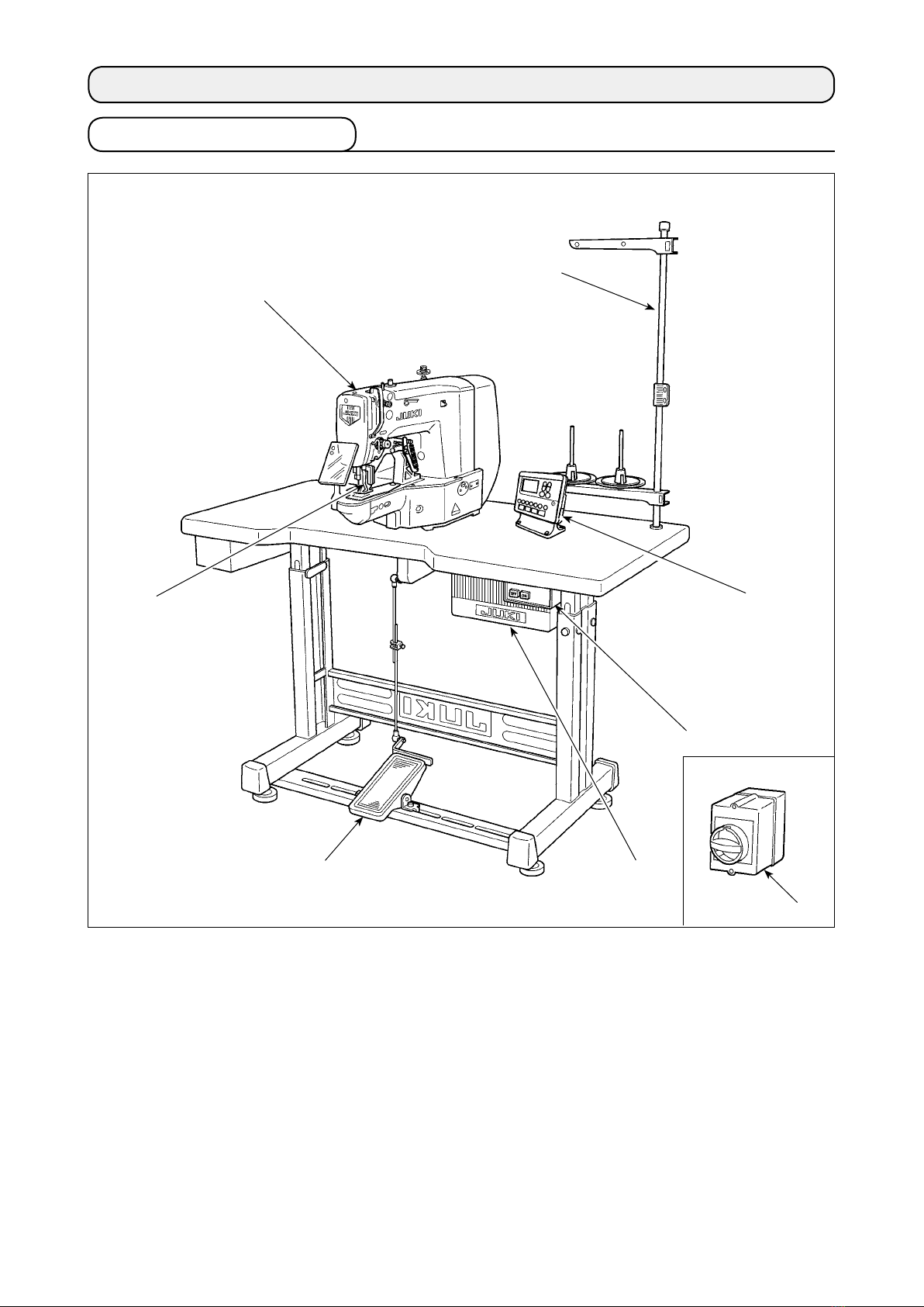
2-1. Names of main unit ........................................... 2
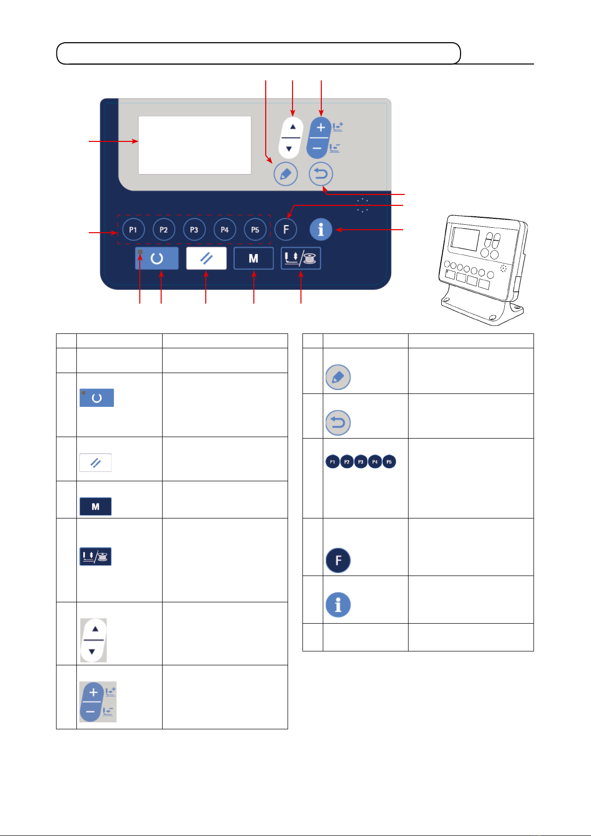
2-2. Names and explanation of switches on the
operation panel.................................................. 3
3. INSTALLATION..................................................4
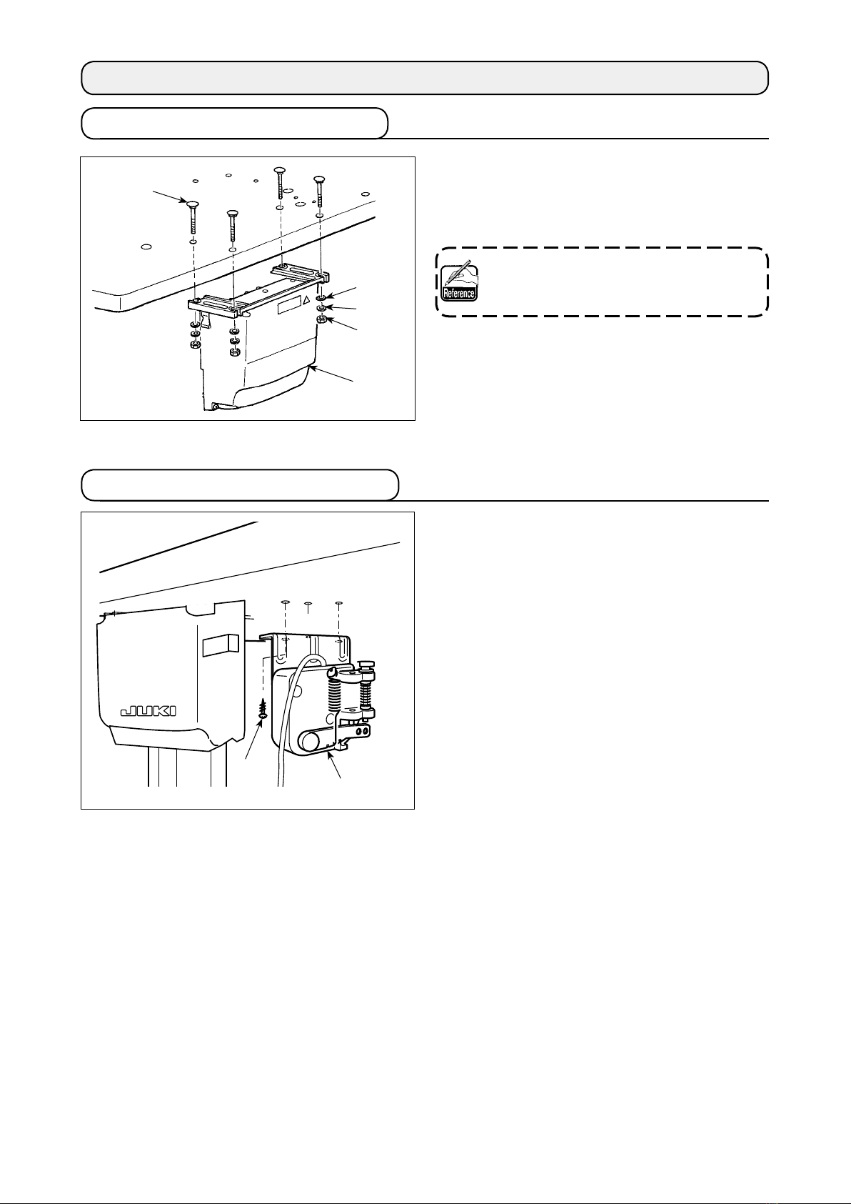
3-1. Installing the electrical box .............................. 4
3-2. Installing the pedal sensor ............................... 4
3-3. Attaching the connecting rod........................... 5
3-4. Installing the head support rod........................ 5
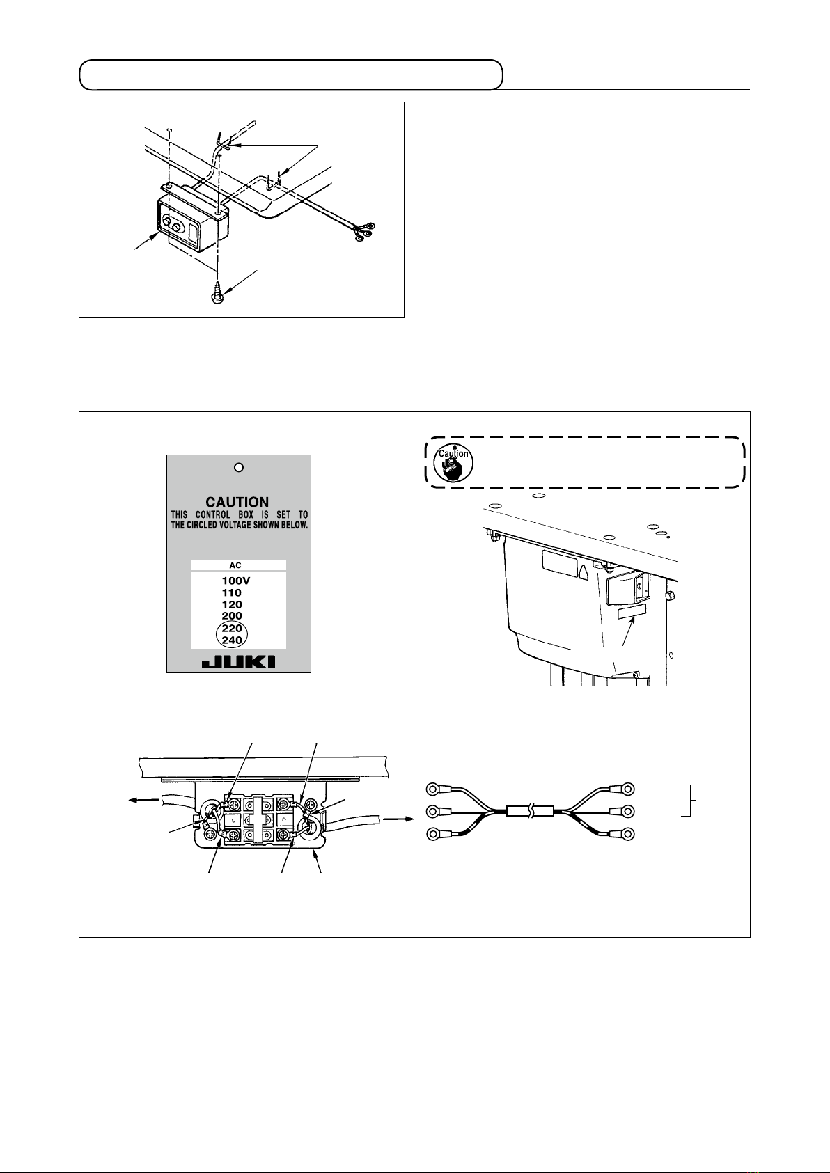
3-5. Installing and connecting the power switch... 6
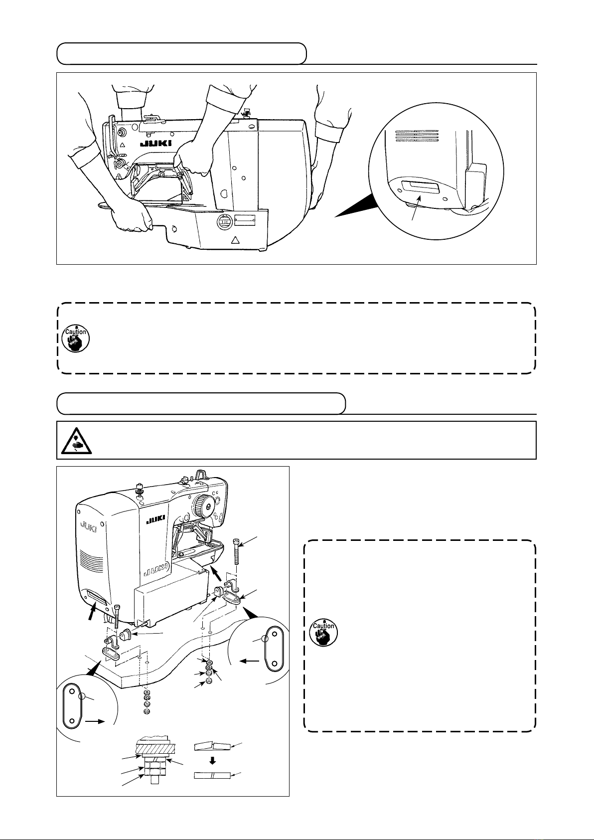
3-6. How to carry the sewing machine.................... 7
3-7. Installation of the sewing machine head......... 7
3-8. Installing the drain receiver and the head
support rubber................................................... 8
3-9. Safety switch...................................................... 8
3-10. Tilting the sewing machine head..................... 9
3-11. Installing the operation panel .......................... 9
3-12. Connecting the cords ..................................... 10
3-13. Handling the cords.......................................... 11
3-14. Installing the eye protection cover................ 12
3-15. Installing the thread stand ............................. 13
3-16. In the case the machine is transported
after factory-completed at the time of
shipment .......................................................... 13
4. OPERATION OF THE SEWING MACHINE.....14
4-1. Lubrication....................................................... 14
4-2. Attaching the needle ....................................... 14
4-3. Threading the machine head.......................... 15
4-4. Installing and removing the bobbin case...... 15
4-5. Installing the bobbin ....................................... 16
4-6. Adjusting the thread tension.......................... 16
4-7. Adjusting the thread take-up spring.............. 17
5. OPERATION OF THE SEWING MACHINE
(BASIC)............................................................17
5-1. Selection of language ..................................... 17
5-2. Setting the pattern number............................. 18
5-3. Setting the item data ....................................... 18
5-4. Checking the contour of a sewing pattern.... 21
5-5. Sewing.............................................................. 22
5-6. Changing the pattern to a different one ........ 22
5-7. Winding a bobbin ............................................ 23
5-8. How to open the tension disk......................... 24
5-9. LED hand light ................................................. 25
6. OPERATION OF THE SEWING MACHINE
(ADVANCED)...................................................26
6-1. Performing sewing using the pattern keys .. 26
6-2. Sewing using the combination function
(cycle sewing).................................................. 31
6-3. Sewing through the use of the counter......... 34
6-4. How to use the temporary stop...................... 37
6-5. Copying or deleting various kinds of
pattern data...................................................... 38
6-6. Communication ............................................... 40
6-7. Cautions in operation...................................... 42
6-8. Setting enable/disable of standard pattern
invoking............................................................ 43
6-9. How to use the F key....................................... 44
6-10. Production support function........................ 45
7. MAINTENANCE...............................................51
7-1. Adjusting the height of the needle bar.......... 51
7-2. Adjusting the needle-to-shuttle relation........ 52
7-3. Adjusting the lift of the work clamp foot....... 53
7-4. The moving knife and counter knife.............. 53
7-5. Adjustment of the wiper.................................. 54
7-6. Draining waste oil............................................ 54
7-7. Amount of oil supplied to the hook ............... 55
7-8. Replacing the fuse........................................... 55
7-9. Replenishing the designated places with
grease............................................................... 56
8. HOW TO USE THE MEMORY SWITCH.........58
8-1. Method of changing memory switch data..... 58
8-2. List of the memory switch functions............. 59
9. OTHERS ..........................................................62
9-1. Table of the standard pattern specications 62
9-2. Table of the standard patterns ....................... 63
9-3. Table of the work clamp foot .......................... 65
9-4. Installing the foot pedal switch (optional)..... 67
9-5. Error list............................................................ 68
9-6. Message list ..................................................... 72
9-7. Troubles and corrective measures (sewing
conditions) ....................................................... 74
9-8. Table of the optional parts.............................. 76
II. EXPLANATION OF THE LK-1903S,
COMPUTER-CONTROLLED HIGH-
SPEED LOCKSTITCH BUTTON
SEWING MACHINE.............................78
1. SPECIFICATIONS............................................78
2. PREPARATION OF THE SEWING MACHINE 78
2-1. Installation of the sewing machine and
preparation of the operation .......................... 78
2-2. Needle and thread ........................................... 78
2-3. Various sewing modes.................................... 79
3. ADJUSTMENT OF THE SEWING MACHINE .80
3-1. Position of the button clamp jaw lever.......... 80
3-2. Adjusting the feed plate.................................. 81
3-3. Adjusting the button clamp jaw lever............ 82
3-4. Adjusting the lifting amount of the button
clamp................................................................ 82
3-5. Adjustment of the pressure of the work
clamp unit ........................................................ 83
3-6. Adjustment of the wiper spring...................... 83
4. OTHERS ..........................................................84
4-1. Installing the save button bar (accessory
part) .................................................................. 84
4-2. Model classication according to the
button size ....................................................... 84
4-3. Attaching the shank button (optional)........... 85
III. DRAWING OF THE TABLE ................89