JUKI DDL-9000 Quick start guide

R
ENGINEER’S MANUAL
29338001
No.00
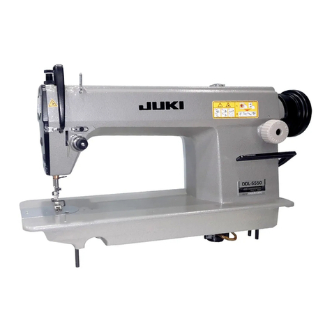
HIGH-SPEED 1-NEEDLE LOCKSTITCH MACHINE WITH
AUTOMATIC THREAD TRIMMER
DDL-9000

PREFACE
This Engineer’s Manual is written for the technical personnel who are responsible for the service and maintenance of
the machine.
The Instruction Manual for this machine intended for the maintenance personnel and operators at an apparel factory
contains operating instructions in detail. And this manual describes “Standard Adjustment, “Adjustment Procedures”,
“Results of Improper Adjustment”, and other important information which are not covered in the Instruction Manual.
It is advisable to use the relevant Instruction Manual and Parts List together with this Engineer’s Manual when carrying
out the maintenance of this machine.

* For the control box and the operation panel, read the Instruction Manual for the SC-900.
CONTENTS
1. OUTLINE .................................................................................................................................1
1-1 Features.........................................................................................................................................................1
1-2 Specifications (Table of DDL-9000 series specifications) ........................................................................2
1-3 Application ....................................................................................................................................................4
1-4 Cautions when operating.............................................................................................................................4
2. OPERATION............................................................................................................................5
2-1 Configuration ................................................................................................................................................5
2-2 Check points before trial operation and operation ...................................................................................5
3. CONFIGURATION...................................................................................................................9
3-1 Adjusting the needle stop position.............................................................................................................9
3-2 Adjusting the wiper (WB type).....................................................................................................................9
3-3 Principle of thread trimming......................................................................................................................10
3-4 Sequence of thread trimming ....................................................................................................................10
3-5 Observing and adjusting the thread trimmer cam timing.......................................................................12
3-6 Adjusting the position of moving knife movement .................................................................................13
3-7 Properly installing the counter knife ........................................................................................................15
3-8 Rising amount of the thread tension disk No. 2 ......................................................................................16
3-9 Sharpening the knife blade........................................................................................................................16
3-10 Replacing the moving knife .....................................................................................................................17
3-11 Replacing the thread guide for knife ......................................................................................................18
3-12 Adjusting the thread take-up picker .......................................................................................................18
3-13 Adjusting the clutch plate and the thread trimmer solenoid................................................................19
3-14 Driving arm stopper..................................................................................................................................19
3-15 Installing/removing the knife installing base .........................................................................................20
3-16 Adjusting the position of the touch-back switch...................................................................................21
3-17 Adjusting the position of the handwheel ...............................................................................................21
3-18 Adjusting the automatic presser lifter (AK118) .....................................................................................21
3-19 Optionals (Presser foot micro-lifter) .......................................................................................................25
3-20 AE-8 (Bobbin thread remaining amount detector) ................................................................................25
3-21 ED-4 (Compact material end sensor)......................................................................................................25
3-22 PK-70 and -71 (3-step pedal)....................................................................................................................25
3-23 Adjusting the tension release change-over ...........................................................................................26
3-24 Adjusting the presser foot micro-lifter ...................................................................................................26
3-25 Installing the operation panel..................................................................................................................26
3-26 Dimensions of table..................................................................................................................................27
3-27 Points of adjustment and assembly of the feed mechanism ...............................................................28
3-29 Points of adjusting and assembling the thread take-up and the needle bar mechanism .................34
3-29 Replacing the motor .................................................................................................................................35
3-30 Replacing the timing belt .........................................................................................................................35
3-31 Points of adjusting and assembling of the bobbin winder...................................................................36
3-32 Points of adjusting and assembling of the lubrication mechanism (SS, SH) .....................................37
3-33 Applying the exclusive grease ................................................................................................................38
3-34 Removing/attaching the gear box cover ................................................................................................39
3-35 Points of adjuting the sewing..................................................................................................................40
3-36 Adjusting the amount of oil in the hook ................................................................................................. 42
4. TROUBLES AND CORRECTIVE MEASURES (MECHANICAL PARTS)............................44
5. TROUBLES IN SEWING AND CORRECTIVE MEASURES ................................................50
6. BOBBIN CASE WITH IDLE-PREVENTION SPRING ...........................................................60
−1 −
1. OUTLINE
1-1 Features
1) Different from the conventional sewing machines with oil pan type, this machine has no oil reservoir and stain
of the materials and oil stain when performing maintenance or moving the machine do not occur.
2) For DS type, an exclusive complete dry hook is employed and there is no oil tank. It is possible to completely
protect the sewing materials from oil stain.
3) A compact AC servomotor is built in the machine head. It is not necessary to fix the belt on the machine head
when setting up the machine, and to perform adjustment as before. In addition, there is no stain from the worn
powder of V-belt.
4) Workability such as handling of materials, easy-to observe needle entry area, etc. is taken seriously. Sewing
space is enough expanded.
5) Noise and vibration when sewing are decreased to improve the sewing environment and to decrease the
operator’s burden.
6) Smooth feeding of materials has been obtained by the improvement of feed dog and thread take-up lever. As
a result, low-tension sewing has been realized.
7) Calibration markings have been added to the respective adjusting sections such as presser spring regulator
and so on considering adjusting operations.
8) The superior portions of JUKI existing lockstitch machines with automatic thread trimmer have been succeeded
to the operation panel and the control box of these machines, and reliability and easy operability have been
improved.

−2 −
1-2 Specifications (Table of DDL-9000 series specifications)
1
2
3
4
5
6
7
8
9
10
11
12
13
14
15
16
17
18
19
20
21
22
23
24
25
26
27
28
29
30
31
32
Max. sewing speed
Bed size
Number of revolution of resistor pack
Max. stitch length (normal/reverse
feed)
Needle bar stroke
Thread trimming system
Bobbin winder
Wiper (WB only)
Automatic reverse feed
Lubrication system
No. of needle used
Lift of presser foot (knee lifter)
Throat plate
Feed dog (Part No.)
Presser foot (standard)
Kind of hook (Part No.)
Part No. of needle bar
Thread tension (asm.) (Part No.)
Thread take-up spring
Thread tension spring
Presser spring
Bobbin case asm.
Bobbin
Feed dog height (reference)
Lubrication of needle bar
Drive system
Transmission mechanism
Motor output
Power supply
Solenoid drive power source
Additional function
Device/optional
SS (Minute-quantity lubrication type)
5,000 rpm
* 4,000 rpm or less when stitch length is 4 mm
or more and RP hook is used.
178 mm X 517 mm
4,000 rpm (excluding a part of export territory)
5 mm
30.7 mm
Horizontal type
Built-in at top surface of machine head type
(with bobbin thread retainer)
Side sweeping type driven by solenoid
Built-in solenoid type
Lubricating to oil tank for hook lubrication
Use New Defrix Oil No. 1.
By plunger pump
Equivalent to DB X 1 #9 to 18 (Equivalent to
SCHMETZ Nm65 to 110)
10 mm (max. 15 mm, AK : max. 10 mm)
Standard : 3-row 11028008
(with engraved marker line)
Export standard : 4-row B1109012i0B
B1613012A00 (3-row feed dog),
B1613012i00 (4-row feed dog)
B15240120BA (excluding a part of export
territory)
Lubrication hook (11038650)
Lubrication hook with needle guard
(11141355)
For DB X 1 (11035003)
FOR SCHMETZ (11141207)
Standardwith calibration markings (23626054)
Standard (22921605)
Standard (22921704)
Standard (B1505227000A)
11038759 (standard with spring)
B9117552A00 (aluminum)
For export B911701200 (iron)
0.75 to 0.85 mm (standard)
Minute-quantity lubrication by oil wick
Built-in compact AC servomotor
Timing belt system
Rated output 450W
3-phase 200V, single phase 100V
DC 34V
Micro-lifter screw is provided as standard.
Tension release reset function when sewing
thick overlapped section
AK-118 (window plate type auto-lifter)
AE-8 (bobbin thread remaining amount
detector)
ED-4 (compact material end detector)
Dial micro-lifter
Turret presser (existing one can be used.)
Optional switch (23632656)
Exclusive grease for maintenance
500g tin (Part No. 23640204)
DS (dry-head type)
4,000 rpm
←
←
←
←
←
←
←
←
Oil tank is not provided (complete
nonlubrication).
←
←
←
←
←
RP hook (22890206)
RP hook with needle guard (22890404)
For DB X 1 (22886907)
For SCHMETZ (22887004)
←
←
←
←
22896252 (with spring for dry-head)
←
←
Nonlubrication
←
←
←
←
←
←
←
←
AE-8 (bobbin thread remaining amount
detector)
* Replace with existing RP hook (11079456).
This device can be used only when sewing
speed is 3,000 rpm or less.
←
←
←
←
←

−3 −
1
2
3
4
5
6
7
8
9
10
11
12
13
14
15
16
17
18
19
20
21
22
23
24
25
26
27
28
29
30
31
32
Max. sewing speed
Bed size
Number of revolution of resistor pack
Max. stitch length (normal/reverse
feed)
Needle bar stroke
Thread trimming system
Bobbin winder
Wiper (WB only)
Automatic reverse feed
Lubrication system
No. of needle used
Lift of presser foot (knee lifter)
Throat plate
Feed dog (Part No.)
Presser foot (standard)
Kind of hook (Part No.)
Part No. of needle bar
Thread tension (asm.) (Part No.)
Thread take-up spring
Thread tension spring
Presser spring
Bobbin case asm.
Bobbin
Feed dog height (reference)
Lubrication of needle bar
Drive system
Transmission mechanism
Motor output
Power supply
Solenoid drive power source
Additional function
Device/optional
DF
(for extra-light-weight materials, foundation)
3,500 rpm
178 mm X 517 mm
3,500 rpm (excluding a part of export territory)
4 mm
30.7 mm
Horizontal type
Built-in at top surface of machine head type
(with bobbin thread retainer)
Side sweeping type driven by solenoid
Built-in solenoid type
Oil tank is not provided (complete
nonlubrication).
Equivalent to DB X 1 #8 to 11 (Equivalent to
SCHMETZ Nm65 to 75)
Equivalent to DB X 1SF #9 to 11
10 mm (max. 15 mm), AK : max. 10 mm
Standard : 4-row 11001906 (with engraved
marker line)
Export standard : 4-row B1109012i0B
B1613155W00 (4-row feed dog),
B1613012i00 (4-row feed dog)
B1524555DBB (excluding a part of export
territory)
RP hook (22890206)
Hook with needle guard (22890404)
For DB X 1 (22886907)
For SCHMETZ (22887004)
For light-weight materials with calibration
markings (23627250)
Low tension (D3128555D00)
Low tension (D3129555D00)
Extra low tension (11162104)
22896252 (with spring for dry-head)
B9117552A00 (aluminum)
0.75 to 0.85 mm (standard)
Nonlubrication
Built-in compact AC servomotor
Timing belt system
Rated output 450W
3-phase 200V, single phase 100V
DC 34V
Micro-lifter screw is provided as standard.
Tension release reset function when sewing
thick overlapped section
AK-118 (window plate type auto-lifter)
AE-8 (bobbin thread remaining amount
detector)
* Replace with existing RP hook (11079456).
This device can be used only when sewing
speed is 3,000 rpm or less.
ED-4 (compact material end detector)
Dial micro-lifter
Turret presser (existing one can be used.)
Optional switch (23632656)
Exclusive grease for maintenance
500g tin (Part No. 23640204)
SH for heavy-weight material)
4,500 rpm
(4,000 rpm or less when stitch length is 4 mm
or more.) ←
4,000 rpm
5 mm
35 mm
Movingknife for thick thread with bobbin thread
clamp ←
←
←
Lubricating to oil tank for hook lubrication. Use
New Defrix Oil No. 1. Plunger pump is used.
Equivalent to DB X 1 #19 to 23
(Equivalent to SCHMETZ Nm120 to 160)
←
Standard : 4-row 11400801
11403003 (4-row feed dog)
D1524555EBL
Lubrication hook (11092251)
H type (11091303)
For heavy-weight materials with calibration
markings (23626062)
Standard (22921605)
High tension (22962005)
High tension (B1505552000A)
11038759 (standard with spring)
B9117012000 (iron)
1 to 1.2 mm (standard)
Minute-quantity lubrication by oil wick
←
←
←
←
←
←
←
←
AE-8 (bobbin thread remaining amount
detector)
←
←
←
←
←
(Table of DDL-9000 series specifications)

−4 −
1-3 Application
1) Standard type (SS)
It is suited for the wide using range from light-weight general fabrics to medium- and heavy-weight fabrics.
(It is especially suited for the process for which a high speed revolution of the sewing machine is required or
the process for which hook lubrication is required in accordance with the nature of thread used.)
2) Dry type (DS)
It is suited for the wide using range from light-weight general fabrics to medium- and heavy-weight fabrics.
(It is most suited for the process of sewing newly developed materials in the market of ladies’ wear, shirts, silk,
coat, etc., or the complete dry process of light-weight fabric, etc. to which the oil stain is particularly disliked.
3) For hard-to-sew materials and foundation garment (DF)
It is suited for the process for which handling performance under low speed and low pressure of presser foot
is particularly required when sewing foundation garment or the like.
(Particularly, this type is effective for the assembly process of brassieres or the like, or sewing hard-to-sew
materials. It is suited for the process for which handling at low speed is required.)
4) For heavy-weight materials (SH)
It is suited for sewing heavy-weight materials such as denim, vinyl leather, etc.
1-4 Cautions when operating
1) Be sure to drain oil from oil tank and attach the air vent cap (red rubber cap) attached to the air vent (gold
bushing) located on the side of machine bed when transporting the sewing machine.
2) When placing the SS or SH type sewing machine head on a stand or the like before setting up the sewing
machine head on the table, take care whether there is a protrusion under the machine head to protect the oil
tank from damage.
3) Even when using RP hook with the SS type machine, do not drain oil from oil tank. (Seizure of hook shaft
metal will result.)
In addition, when using the RP hook, loosen the oil amount adjusting screw until it will go no further and adjust
so that oil does not come out from the front of hook shaft.
4) To protect accident when performing maintenance, be sure to securely set the safety switch connector to the
control box.
5) Oil is kept in the gear box for lubrication. Replacement of oil is not necessary. Do not remove the lid of gear
box unless it is necessary.
* When the lid of the box has been removed, it is necessary to replace the packing with a new one.
6) When making the sewing machine run idle, be sure to operate the sewing machine after removing the bobbin
case.
When the bobbin thread is in the bobbin case, the thread is protruded from the bobbin case by running idle of
the machine and the thread is entangled in hook race or hook shaft. As a result, the machine will be out of
order.

−5 −
(1)
(2)
(5)
(4)
(3)
(6)
(7)
(10)
(16)
(19)
(8)
(9) (12) (13)
(15)
(11)
(14)
(17)
(18)
2. OPERATION
2-1 Configuration
(1) Power switch (8) Touch-back switch (14) Tension release change-over screw
(2) Operation panel (9) Wiper device (15) Micro-lifter screw
(3) Pulley cover (10) Screw for level adjustment (16) Under cover
(4) Thread stand of table/stand (Caster) (17) Oil hole
(5) PSC box (11) Resistor pack (18) Air vent
(6) Max. speed control knob (12) Bobbin winder
(19) Oil amount indication window (SS, SH)
(7) Operation pedal (13) Thread trimmer retainer
2-2 Check points before trial operation and operation
1) Make sure that the wiring to the control box is securely performed.
2) Make sure that the safety switch securely works. (Check whether the warning buzzer beeps when the sewing
machine head is tilted.)
3) Check that the red rubber cap of air vent (17) located on the front side of machine bed has been removed.
4) First, make the sewing machine run at low speed and check that there is no abnormal noise.
5) Depress the back part of the pedal and check that the thread trimmer securely functions.
6) For the SS type, check that oil is kept in oil tank.
7) For the SS type, check that the amount of oil in the hook is appropriate.
Fig. 1

−6 −
(1) Power switch
Power switch for motor, PSC, operation panel, etc.
(2) Operation panel
This panel can set automatic reverse feed stitching, pattern sewing, etc.
(3) Pulley cover
This is a cover for safety and prevents dust which enters inside motor.
(4) Thread stand
(5) PSC box
Circuits to control the sewing machine and motor, output circuits to function the respective outputs (thread
trimmer solenoid, back solenoid, etc.), pedal sensor to detect the pedal operation, and power circuits to function
the respective functions are stored in this box.
(6) Max. speed control knob (Max. speed limitation variable resistor)
This is a variable resistor to limit the maximum speed by analog.
(7) Operation pedal
Speed control of sewing machine, thread trimming operation or presser lifting operation (for AK-118 type only)
can be performed through the operation of depressing the front part or back part of the pedal.
(8) Touch-back switch
This is a hand operated switch to perform reverse feed stitching.
(9) Wiper device
Needle thread after thread trimming is wiped out by wiper signal output from the PSC box.
(10) Screw for level adjustment of table/stand (Caster)
Adjust the screw in accordance with the floor on which the operator works so that there is no play and less
vibration.
(11) Resistor pack
This is used to automatically identify the model of sewing machine used.
(12) Bobbin winder
This is a bobbin winder built in the machine hed.
(13) Thread trimmer retainer
This works to cut and retain bobbin thread wound with the bobbin winder.
(14) Tension release change-over screw
When handling the materials at the corner of thick overlapped section or the like by using the knee lifter, this
screw makes thread release work and prevents thread from partial defective thread tightness.
(15) Micro-lifter screw
When sewing hard-to-sew materials such as velvet or the like, sewing can be performed in a condition that
the presser foot is slightly lifted.
(16) Under cover
This cover prevents lint or dust which occurs at the time of sewing from falling on the floor.
(17) Oil hole
For the SS and SH types, when oiling into oil tank, use this hole after removing the cap.
(18) Air vent
This is used to prevent the inside pressure from being increased due to rise of tempearture in the gear box
when the sewing machine is operated.
(19) Oil amount indication window (SS, SH)
This indicates the oil amount in oil tank. Fill oil when the top end of indication rod comes to the lower engraved
marker line.

−7 −
(Trial operation)
1) Operation when the power is turned ON
When turning ON the power switch, the sewing machine rotates up to the needle-up position excluding the
case where the needle position at that time is the position other than the up-stop position and stops at needle-
up position.
2) Pedal operation
Pedal can be operated in four steps.
①The machine runs at low sewing speed when you lightly depress the front part of the pedal.
②The machine runs at high sewing speed when you further depress the front part of the pedal. (However, when
the automatic reverse feed stitching switch is preset, the machine runs at high speed after it completes reverse
feed stitching.)
③The machine stops (with its needle up or down according to the set of stop position) when you reset the pedal
to stop (neutral).
④The machine trims threads and stops with its needle up when you fully depress the back part of the pedal.
○The machine will completely perform thread trimming even if you reset the pedal to its neutral position
immediately after the machine started thread trimming action.
At this time, if you depress the front part of the pedal instead of neutral, thread trimming is performed
normally. However, safety circuit works and the machine continues to stop after completing thread trimming.
At this time, return the pedal to the neutral position once.
○Wiper works when the wiper is provided (WB type).
High speed
Low speed
Stop
Thread
trimming
High speed
Low speed
Stop (neutral)
Thread trimming
Fig. 2

−8 −
3) Pedal operation with the pedal type auto-lifter (AK118)
Pedal can be operated in five steps.
①The machine runs at low speed when you lightly depress the front part of the pedal.
②The machine runs at high speed when you further depress the front part of the pedal. (However, when the
automatic reverse feed stitching switch is preset, the machine runs at high speed after it completes reverse
feed stitching.)
③The machine stops (with its needle down) when you reset the pedal to stop (neutral).
④The presser foot goes up when you lightly depress the back part of the pedal.
⑤If you furthrer depress the back part, the presser foot comes down and the thread trimmer is actuated. After
the machine has stopped with its needle up, the presser foot goes up.
○Wiper works when the wiper is provided (WB type).
High speed
Low speed
Stop
Presser foot lifting
Thread trimming
High speed
Low speed
Stop (neutral)
Presser foot lifting
Thread trimming
Fig. 3

−9 −
3. CONFIGURATION
3-1 Adjusting the needle stop position
1) Adjusting the upper stop position (Upper stop position
after thread trimming)
The standrad needle stop position is obtained, when
needle stops after thread trimming, by aligning the red
marker dot on the machine arm with the white marker
dot on the handwheel.
Stopthe needle inits highest position,andloosen screw
(A) in the figure on the right to perform adjustment within
the slot of the screw.
○To advance needle stop position →Direction (1)
○To delay needle stop position →Direction (2)
2) Adjusting the lower stop position
The lower needle stop position when the pedal is
returned to the neutral position after the front part of
the pedal is depressed can be adjusted by loosening
screw (B) in the figure on the right and adjusting within
the slot of the screw.
○To advance needle stop position →Direction (1)
○To delay needle stop position →Direction (2)
[Caution] Do not rotate the machine with screws (A)
and (B) loosened.Just loosen the screws,
and do not remove them.
3-2 Adjusting the wiper (WB type)
1. Adjusting the wiper position
Adjust the wiper position in accordance with the thickness
of fabric to be sewn.
Normally, adjust it as follows :
1) Turn the handwheel in the normal direction to align white
marker dot (1) with marker dot (2) on the machine arm.
2) Insert wiper (3) into wiper shaft (4) so that a clearance
of 2 mm is provided between the top end of the wiper
and the top end of the needle. At this time, adjust so
that the distance from the flat section of the wiper to
the center of the needle is 1 mm. Securely fix the wiper
with wiper adjusting screw (5) as if pressing wiper (3)
with wiper collar (6) .
[Caution] Do not loosen the wiper solenoid setscrew.
When the wiper is not used, turn OFF the
wiper seesaw switch.
(1)
(2) (A)
(1)
(2)
(B)
(1)
(2)
(5)
(4)
(3)
(6)
1 mm
2 mm
Fig. 4
Handwheel
Fig. 5
Fig. 6
Fig. 7
Wiper seesaw
switch
Fig. 8

−10 −
3-3 Principle of thread trimming
[Caution] This sequence shows the state that the automatic reverse feed stitching switch is turned ON at
the start of sewing and at the end of sewing.
1. Blade point of hook scoops needle thread. 2. Moving knife handles threads (recedes).
3. Moving knife catches needle and bobbin threads (advances).
Fig. 9
Fig. 10
4. Thread trimming
3-4 Sequence of thread trimming
Power
switch ON
Depress front part
of pedal
Needle goes up.
Reverse feed stitching at
sewing start
Detection
Pedal neutral
position Needle down
stop
Depress back
part of pedal
Reverse feed stitching
at sewing end
Cam engagement
Tension release
Sewing machine rotates from
needle down to needle up.
Knife catches
thread.
Thread handling
Thread trimmer
solenoid is actuated.
Thread
trimming
Up-stop
signal
Thread trimmer solenoid OFF
End of tension release
Cam and roller are
disengaged.
Sewing machine stops
with needle up.
Low speed to
high speed

−11 −
(Reference) 1.Markerdot onthehandwheel shows the standard value of cam timing. The timing can be more advanced
by 2˚ or more delayed by 5˚ than that in case of cotton thread or synthetic thread. At this time, however,
confirm that moving knife securely separates two pieces of needle thread at the bottom face of throat
plate. If the cam timing is excessively advanced or delayed, the needle thread remaining at the top of
needle will be shorter and may slip from the needle immediately after thread trimming. In addition,
roller may not enter the groove of thread trimmer cam. So, be careful.
2. Basically, the thread trimmer cam timing is common to cotton thread and synthetic thread. For the thin
synthetic thread, however, if the following troubles occur :
①One or several stitches skip at the start of sewing.
②Thread slips from needle at the start of sewing.
Perform the following adjustments for synthetic thread (special) (In case of thin threads)
③Align marker dot on the machine arm (Fig 13 (3)) with green marker dot on the handwheel (Fig.
13 (1)) and adjust thread tension No. 1 to lengthen the thread remaining on the needle after
thread trimming within the range that nothing interferes with the finish of sewing.
④Make one stitch of soft start at the start of sewing.
[Caution] Adjustment ①is not applied to thick threads.
When thread trimmer cam timing is delayed (in the direction of green), phenomena such as
dispersion of adjustment, non-trimming of thread without completing thread trimming depending
on the kinds of threads may occur.
In this case, slightly delay the needle upper stop position.

−12 −
2) Adjusting the thread trimmer cam timing
First, loosen two setscrews (Fig. 12) in the thread
trimmer cam in the order of No. 1 and No. 2, and align
marker dot on the hand wheel with marker dot on the
machine arm. (Fig. 13 (1) and red (2) or green (3) )
Next, pressing thread take-up picker (Fig. 12 (1) ) to
the right, engsage cam and roller, turn cam only with
finger top in the reverse direction as against the rotating
direction of hook driving shaft without turning the hook
driving shaft (arrow mark in Fig. 12). Press the cam to
roller (Fig. 12) at the position where the cam does not
rotate, and tighten setscrews in the cam in the order of
No. 2 and No. 1.
When the cam collar has not been moved, press the
thread trimmer cam to the cam collar and tighten the
setscrews in the order of No. 2 and No. 1.
(1)
(1)
(2)
(3)
3-5 Observing and adjusting the thread trimmer cam timing
1) Proper observing of the thread trimmer cam timing
Thread trimmer cam timing for both cotton and synthetic threads can be easily adjusted by aligning marker dot
on the machine arm with that on the handwheel.
Tilt the machine head, turn the handwheel by hand until the thread take-up lever goes up slightly near the
upper dead point, press thread take-up picker (Fig. 12 (1)) to the right with fingers, and roller enters the cam
groove of thread trimmer cam to engage with each other. At the same state, turn the handwheel in the reverse
direction as against the normal operation of the sewing machine, and there is a position where the sewing
machine does not rotate. At this time, adjust the cam timing so that marker dot (Fig. 13 (1)) of the machine arm
shown in Fig. 13 is aligned with marker dot (Fig. 13 (1)) on the handwheel. This is the cam timing for cotton
thread and synthetic thread.
Thread trimmer cam
Setscrew No. 2
Cam collar
Thread trimmer cam
Turn cam by hand in
this direction.
Roller
Fig. 12
Green
Red
Fig. 13

−13 −
3-6 Adjusting the position of moving knife movement
1) Proper movement of the moving knife
The position of moving knife when it moves until it will go no further is the position where the front top end of
moving knife is receded 2.5 to 3 mm from the center of the needle. When the amount of recession is excessively
small, the moving knife cannot scoop needle thread or bobbin thread when trimming thread, and if the amount
is excessively large, feed dog may come in contact with moving knife. Therefore, properly adjust the moving
knife position.
Reference for positioning the moving knife at the predetermined position is the position where the V groove
indicated on the knife installing base is aligned with the periphery of moving knife.
2) Adjusting the moving knife position
Adjustment is performed by changing the right and left positions of moving knife link pin (Fig. 15 (1)) when the
sewing machine stops.
①Loosen the lock nut of moving knife link pin (Fig. 15 (1)).
②Following the predetermined position in Fig. 14, move the moving knife link pin to the left and right so that
V groove (Fig. 14) for positioning moving knife on the knife installing base is aligned with the periphery of
moving knife.
③Tighten the lock nut of moving knife link pin at the proper position.
Set the position of moving knife pin to the right to increase the amount of recession, and to the left to
decrease the amount.
3) When adjustment cannot be performed by moving knife link pin only
①Loosen the lock nut of moving knife link pin (Fig. 15 (1)).
Fig. 14
2.5 to 3 mm
Moving knife
Center of needle
When moving knife recedes most.
0.5 mm
(0.2 to 0.7)
V groove for positioning
moving knife
Predetermined position

−14 −
②Adjust so that the center of moving knife link pin
is aligned with V groove (Fig. 15 (2)) of the center
of slot in knife driving arm (Fig. 15 (3)), and tighten
the lock nut to fix the pin.
③Loosen two setscrews (Fig. 15 (4)) in driving arm
stopper (Fig. 15 (5)).
④Move knife driving arm (Fig. 15 (2)) so that V
groove (Fig. 14) on the knife installing base is
aligned with the periphery of moving knife, press
it to driving arm stopper (Fig. 15 (4)) at that
position, and tighten setscrews (Fig. 15 (5)).
⑤Loosen the respective two setscrews in thread trimmer cam (Fig. 15 (7)) and cam collar (Fig. 15 (6)).
⑥Align marker dot (red : Fig. 13 (2) or green (3)) on the handwheel with marker dot (Fig. 13 (1)) on the
machine arm.
⑦Turn with finger top setscrew No. 2 (Fig. 15 (7)) in the thread trimmer cam so that it comes to this side, and
press the thread take-up picker to the right when the setscrew comes to this side.
⑧Move the cam to the right and left to engage the cam with the roller.
⑨In this state, lightly pulling the cam to the right, move it in the direction of arrow (this side) until it will rotate
no further.
⑩Temporarily tighten setscrew No. 2 (Fig. 15 (7))
in the cam.
⑪At this time, check the following matters :
a) Marker dot on the handwheel is aligned with
that on the machine arm.
b) Roller smoothly enters the groove in the cam.
c) Amount of recession of knife is 2.5 to 3 mm
(SH : 3 to 3.5 mm).
⑫Securely tighten two setscrews in the cam.
⑬Press cam collar to the cam, and tighten one
setscrew.
[Caution] ○Amount of recession of knife is largely affected even when adjustment of left and right
positions of moving knife link pin is finely performed.
○Check whether moving knife handles thread as shown in Fig. 16.
(1)
(5)
(4)
(3)
(6)
(7)
(2)
Fig. 15
Fig. 16

−15 −
3-7 Properly installing the counter knife
The dimension of proper installation of the counter knife is as shown in Fig. 17. The standard distance from thread
guide for knife attached so that needle enters the center of window to the top end of counter knife blade is 0.5
mm.
At this time, a clearance of approximate
4 mm is provided between the center of
needle and the top end of counter knife
blade.
The top end of counter knife blade is 0.6
mm above the installing face. (Fig. 18)
Sharpness will change when installing
angle of the top end of counter knife blade
is changed. Sharpness is shown only
when cutting blade sections of counter
knife and moving knife are closely
engaged with each other.
When adjusting or replacing the counter
knife, be sure to check the sharpness and
adjust the installing angle of counter knife.
Counter knife can be installed by moving
to the right from the standard installing
position.
At this time, the feeding length of needle
thread and bobbin thread is lengthened
more not only as much as the moving
distance of knife than the standard time,
but also thread trimming timing is delayed.
As a result, the length of needle thread
remaining at the top end of needle is extra
lengthened. (Fig. 20)
For the synthetic thread, move counter knife to the right to delay thread trimming timing.
To completely adjust, however, it is also necessary to adjust thread trimmer cam timing.
(1)
(2)
(3)
0.5 mm
0.6 mm
Moving knife
Thread guide
for knife
Center of needle
Approx.
4 mm
Counter knife
Shorter Longer
Length of thread after trimming
Fig. 17
Counter knife
Fig. 18
Bottom section of throat
plate (Machine bed)
When counter knife is
moved to the right
Moving knife
Hook Thread take-up picker
Fig. 20
Moving knife Counter knife
Fig. 19
To be center Standard

−16 −
Properly installing the thread guide for knife
Install the thread guide for knife so that the needle enters just in the center of the window (hole).
3-8 Rising amount of the thread tension disk No. 2
1) Observing the rising amount of the thread tension disk No. 2
Lift the presser foot at the position where the thread take-up lever comes slightly to this side of its upper dead
point. Then, check that the rising amount of the thread tension disk No. 2 is 0.5 to 1mm when thread take-up
picker (Fig. 12 (1)) is pressed to the right.
2) Adjusting the rising amount of the thread tension
disk No. 2
①To increase the rising amount, loosen screw
(Fig. 21 (1)) and move thread release wire (2)
to the right.
②To decrease the rising amount, loosen screw
(1) and move thread release wire (2) to the
left. After performing adjustment, securely
tighten screw (1).
3-9 Sharpening the knife blade
The shape of blade top of the counter knife affects most the sharpness of the knife.
In many cases, the sharpness is improved by sharpening the blade of the counter knife only.
It is important that the blade face of the counter knife comes in contact with the blade section of the moving knife.
○The sharpness is improved by sharpening face A in Fig. 22 only. (Pay attention to the angle shown in Fig. 22.)
(1)
(2)
X
DC
Take corner and polish well.
Fig. 21
○The sharpness is deteriorated when the top end of face B has been worn out and got round. Carefully sharpen
the blade without changing the angle.
Sharpen this face. (Face A)
Blade top (Face B) Counter knife
Fig. 22
Moving knife Counter knife
C and D sections of moving knife should
simultaneously come in contact with counter knife.
Fig. 23

−17 −
○When the sharpness is insufficient although the blade
face is enough sharpened, it is because the left and
right blade faces of moving knife and counter knife
do not simulataneously come in contact with each
other. At this time, adjust the inclination of the counter
knife.
(Reference) To improve the contact of the blades
of moving knife and counter knife, it is
effective to change the angle of the
arrow mark shown in Fig. 24.
When the side of D in Fig. 23 is hard to
cut, decrease this angle, and when the
side of C is hard to cut, increase the
angle.
3-10 Replacing the moving knife
When replacing the moving knife, replace it in the
following procedure.
1) Remove moving knife hinge screw (Fig. 26 (1)).
2) Slide moving knife link (Fig. 26 (2)) to this side, and
draw moving knife link (2) from knife forked pin (Fig.
26 (3)).
3) Loosen and take out moving knife hinge screw (Fig.
25 (3)) using 3 mm hexagonal wrenck key (Fig. 25
(4)).
4) Loosen and remove knife forked base hinge screw
(Fig. 25 (1)). Lift up knife forked base (Fig. 25 (2))
and remove the pin of moving knife from the forked
groove in the knife forked base.
5) Remover the pin of moving knife, slide the moving
knife to the left and take it out from the bottom face
of knife forked base.
Perform installation in the reverse order of the
aforementioned procedure.
When tightening the moving knife hinge screw, move
the moving knife by hand and check that it smoothly
moves without play.
Next, securely insert the forked groove in the knife forked
base into the moving knife pin, and tighten the knife
forked base hinge screw.
Insert the moving knife link into knife forked pin (Fig. 26
(3)), and attch moving knife link hinge screw
(Fig. 26
(1)
).
Finally, move the moving knife link to the left and right,
and check that the moving knife moves.
(1)
(2)
(4)
(3)
(1)
(2)
(3)
Counter knife
Fig. 25
Fig. 26
Fig. 24
Other manuals for DDL-9000
2
Table of contents
Other JUKI Sewing Machine manuals

JUKI
JUKI AMS-224EN4530R User manual

JUKI
JUKI LU-1520N-7 User manual

JUKI
JUKI TL-2010Q User manual

JUKI
JUKI DLN-9010A User manual

JUKI
JUKI LK-1900S Series User manual

JUKI
JUKI TL-2200QVP Mini User manual

JUKI
JUKI LU-1510N-7 Quick start guide

JUKI
JUKI MO-655 User manual

JUKI
JUKI DU-1181N User manual

JUKI
JUKI AMB-289 User manual

JUKI
JUKI DDL-8700-7 User manual

JUKI
JUKI DDL-555-4 User manual

JUKI
JUKI LU-562 User manual

JUKI
JUKI DDL-900A User manual

JUKI
JUKI LU-2810 Series Quick start guide

JUKI
JUKI HZL-30Z User manual

JUKI
JUKI DLM-5200N User manual

JUKI
JUKI MBH-180 Quick start guide

JUKI
JUKI LK-1942ZA5050 User manual

JUKI
JUKI HZL-NX7 User manual