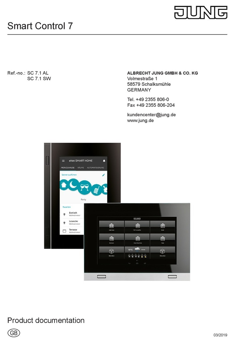
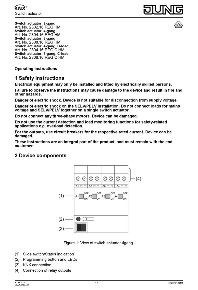
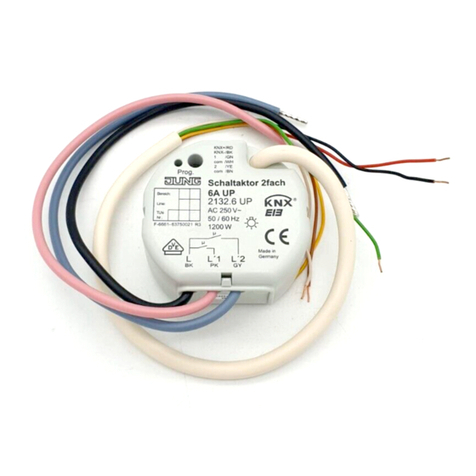
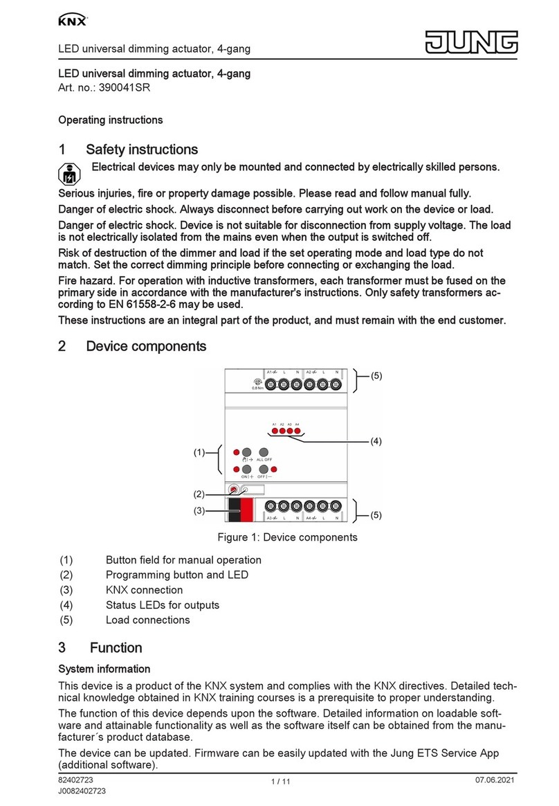
Jung KNX 360061SR User manual
Other Jung Controllers manuals
Jung
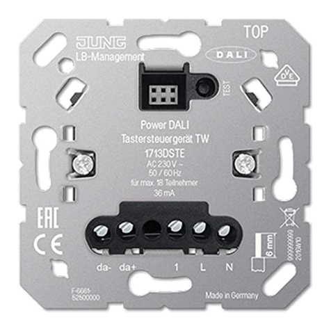
Jung 1713DSTE User manual
Jung
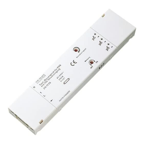
Jung 240-10 EB User manual
Jung
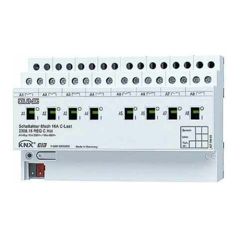
Jung KNX 230 .16 REGHM Series User manual
Jung
Jung Instabus 2134.16 REG User manual
Jung
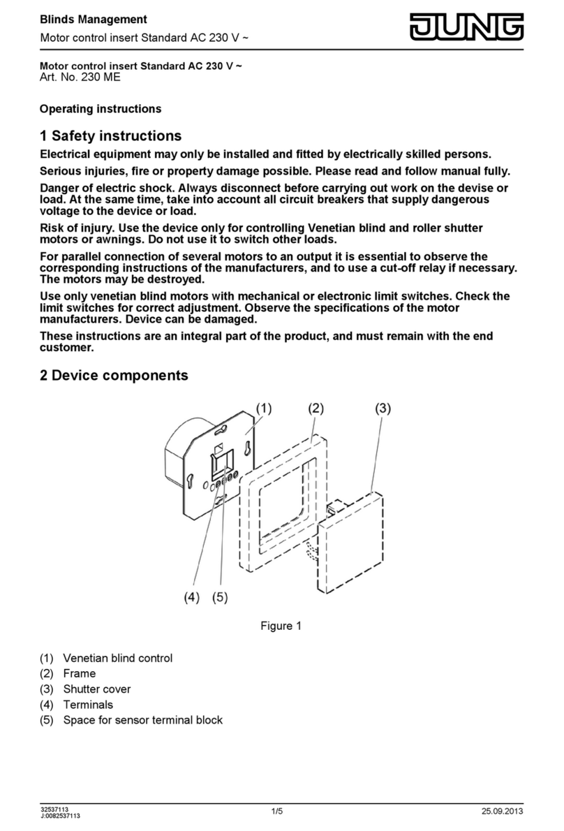
Jung 230 ME User manual
Jung
Jung KNX 2095 LUX User manual
Jung
Jung BTJ1B2U User manual
Jung
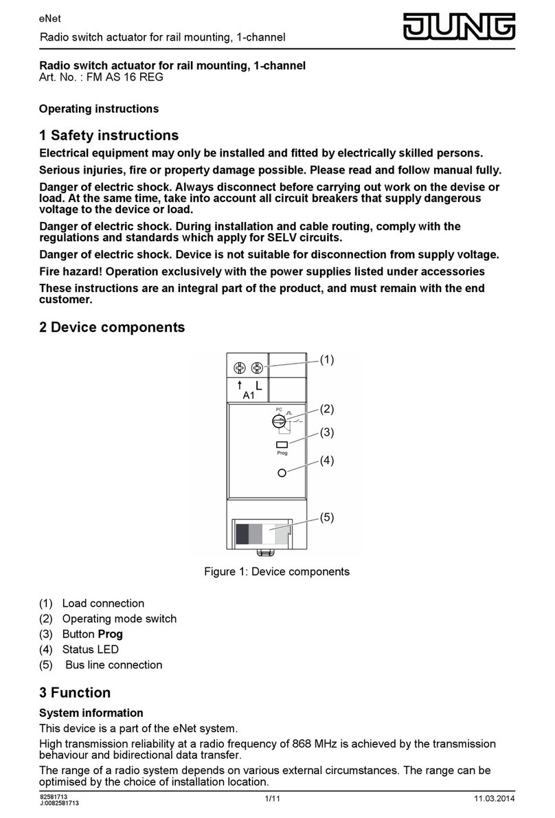
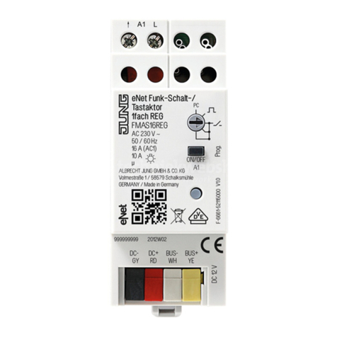
Jung eNet FM AS 16 REG User manual
Jung
Jung FMAS16REG User manual
Jung
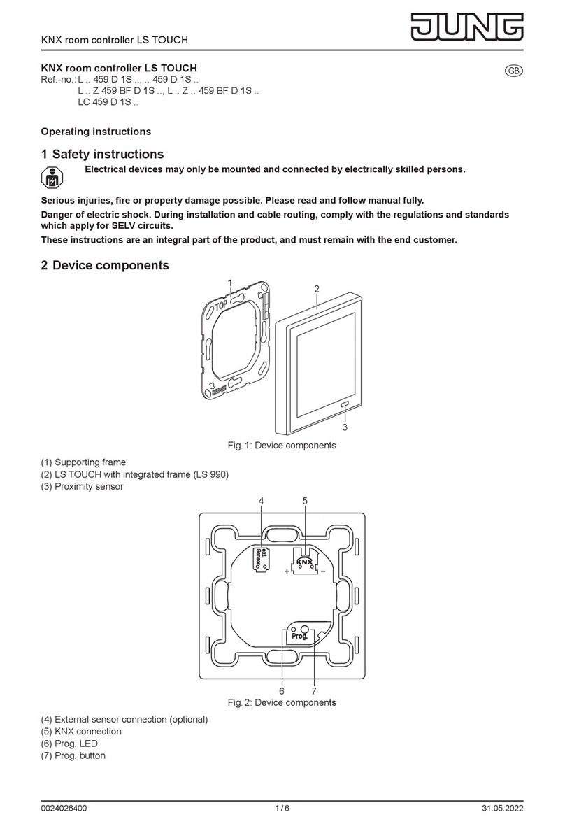
Jung LS TOUCH User manual

Jung
Jung KNX 2095 LUX User manual
Jung
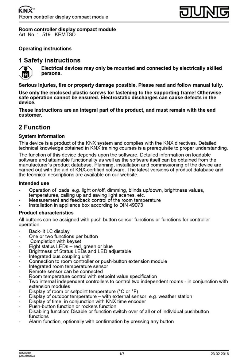
Jung KNX 519 KRMTSD Series User manual
Jung
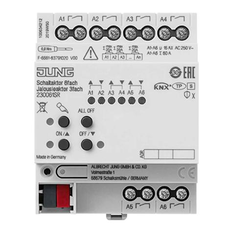
Jung 230061SR User manual
Jung
Jung FST1240EB User manual
Jung
Jung LB management User manual
Jung
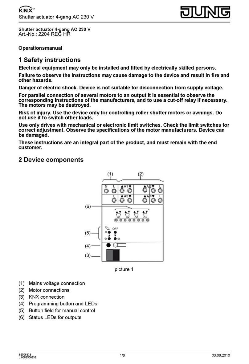
Jung 2204 REG User manual
Jung
Jung 4093 KRM TS D Operator's manual
Jung
Jung Smart Control IP Guide
Jung
Jung KNX 390011 SU User manual
Jung
Jung FM J 50700 REG User manual
Popular Controllers manuals by other brands

Digiplex
Digiplex DGP-848 Programming guide

YASKAWA
YASKAWA SGM series user manual

Sinope
Sinope Calypso RM3500ZB installation guide

Isimet
Isimet DLA Series Style 2 Installation, Operations, Start-up and Maintenance Instructions

LSIS
LSIS sv-ip5a user manual

Airflow
Airflow Uno hab Installation and operating instructions
