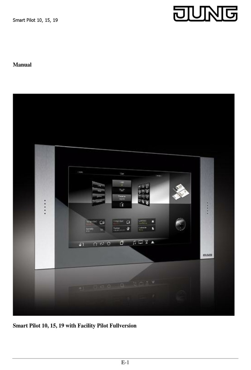
Jung Smart Control SC 1000 KNX Operator's manual

Product documentation
Smart Control
Art. No. SC 1000 KNX
ALBRECHT JUNG GMBH & CO. KG
Volmestraße 1
58579 Schalksmühle
Telefon: +49.23 55.8 06-0
Telefax: +49.23 55.8 06-2 04
www.jung.de
Service Center
Kupferstr. 17-19
44532 Lünen
Germany Issue: 05.12.2013
14505800 1v5.2

Art. No. SC 1000 KNX
Contents
1 Product definition 4 ................................................................................................................
1.1 Product catalogue 4 ...........................................................................................................
1.2 Function 4 ..........................................................................................................................
1.3 Accessories 7 ....................................................................................................................
2 Installation, electrical connection and operation 8 .............................................................
2.1 Safety instructions 8 ..........................................................................................................
2.2 Device components 9 ........................................................................................................
2.3 Fitting and electrical connection 11 ...................................................................................
2.4 Commissioning 15 .............................................................................................................
2.5 Operation 18 ......................................................................................................................
3 Technical data 19 ....................................................................................................................
4 Software description 20 .........................................................................................................
4.1 Software specification 20 ...................................................................................................
4.2 Software "Smart Control 501511" 21 .................................................................................
4.2.1 Scope of functions 21 .................................................................................................
4.2.2 Notes on software 24 .................................................................................................
4.2.3 Object table 25 ...........................................................................................................
4.2.3.1 Push-button extension module 25 ......................................................................
4.2.3.2 Light scene function 32 .......................................................................................
4.2.3.3 Room temperature controller 33 .........................................................................
4.2.3.4 Display 49 ...........................................................................................................
4.2.4 Functional description 62 ...........................................................................................
4.2.4.1 Display functions 62 ............................................................................................
4.2.4.1.1 Display structure 62 ....................................................................................
4.2.4.1.2 Operation concept and sensor evaluation 76 ..............................................
4.2.4.1.3 Channel function "switching" 81 ..................................................................
4.2.4.1.4 Channel function "Dimming (Start/Stop)" 83 ...............................................
4.2.4.1.5 Channel function "Dimming (Brightness value)" 86 .....................................
4.2.4.1.6 Channel function "Venetian blind/shutter (Step/Move/Step)" 89 .................
4.2.4.1.7 Channel function "Venetian blind/shutter (Position)" 94 ..............................
4.2.4.1.8 Channel function "Scene extension" 99 ......................................................
4.2.4.1.9 Channel function "1-byte value transmitter" 102 .........................................
4.2.4.1.10 Channel function "2-byte value transmitter" 105 .........................................
4.2.4.1.11 Channel function "operating mode switchover, internal" 109 ......................
4.2.4.1.12 Channel function "setpoint shift, internal" 111 .............................................
4.2.4.1.13 Channel function "Fan controller, internal" 113 ...........................................
4.2.4.1.14 Channel function "ASCII-Text" 116 .............................................................
4.2.4.1.15 Master button 118 .......................................................................................
4.2.4.1.16 Status line 119 ............................................................................................
4.2.4.1.17 Display illumination and operation LED 121 ................................................
4.2.4.1.18 Displaying measurement data of a weather station 123 .............................
4.2.4.1.19 System settings 128 ....................................................................................
4.2.4.1.20 Cleaning function 138 .................................................................................
4.2.4.1.21 Brightness sensor 139 ................................................................................
4.2.4.2 Push-button extension module 141 ....................................................................
4.2.4.2.1 Button configuration 141 .............................................................................
4.2.4.2.2 Operation concept, button evaluation and button arrangement 142 ...........
4.2.4.2.3 Switching function 146 ................................................................................
4.2.4.2.4 Dimming function 147 .................................................................................
4.2.4.2.5 Venetian blind function 149 .........................................................................
4.2.4.2.6 Value transmitter function 153 ....................................................................
4.2.4.2.7 Scene extension function 156 .....................................................................
4.2.4.2.8 2-channel operation function 157 ................................................................
Product documentation
Page 2 of 347

Art. No. SC 1000 KNX
4.2.4.2.9 "Controller operating mode" function 159 ....................................................
4.2.4.2.10 "Setpoint shift" function 160 ........................................................................
4.2.4.2.11 Status LED 161 ...........................................................................................
4.2.4.2.12 Disabling function 163 .................................................................................
4.2.4.2.13 Alarm signal 166 .........................................................................................
4.2.4.3 Room temperature controller 167 .......................................................................
4.2.4.3.1 Operating modes and operating mode change-over 167 ............................
4.2.4.3.2 Control algorithms and calculation of command values 170 .......................
4.2.4.3.3 Adapting the control algorithms 177 ............................................................
4.2.4.3.4 Operating mode switchover 180 .................................................................
4.2.4.3.5 Temperature setpoints 190 .........................................................................
4.2.4.3.6 Room temperature measurement 203 ........................................................
4.2.4.3.7 Command value and status output 206 ......................................................
4.2.4.3.8 Fan controller 213 .......................................................................................
4.2.4.3.9 Disable functions of the room temperature controller 220 ...........................
4.2.4.3.10 Valve protection 221 ...................................................................................
4.2.4.4 Light scene function 222 .....................................................................................
4.2.4.5 Room temperature controller page 224 ..............................................................
4.2.4.6 Timer switch 226 .................................................................................................
4.2.4.6.1 Definition, function and channel commands 226 .........................................
4.2.4.6.2 Astro and random function 229 ...................................................................
4.2.4.6.3 Setting switching times 231 .........................................................................
4.2.4.7 Delivery state 240 ...............................................................................................
4.2.5 Parameters 241 ..........................................................................................................
4.2.5.1 Display 241 .........................................................................................................
4.2.5.2 Controller function 284 ........................................................................................
4.2.5.3 Temperature measurement 309 .........................................................................
4.2.5.4 Push-button extension module 311 ....................................................................
4.2.5.5 Scene 342 ..........................................................................................................
5 Appendix 345 ...........................................................................................................................
5.1 Index 345 ...........................................................................................................................
Product documentation
Page 3 of 347

Art. No. SC 1000 KNX
1 Product definition
1.1 Product catalogue
Product name: Smart Control
Use: Sensor / Display
Design: FM (flush-mounted)
Art. No. SC 1000 KNX
1.2 Function
The Smart Control is a control and display unit for controlling and visualising building functions.
The device has a TFT graphic colour screen (10.9 cm, 800 x 480 pixels, 16.7 million colours)
with a touchscreen sensor surface. The display elements are operated by simply touching the
glass surface directly.
The Smart Control can be integrated into the KNX building systems with the aid of the KNX
communication module. This device then combines the functions of a KNX/EIB bus coupling
unit, push button sensor, room temperature controller, timer and display unit in just one bus
subscriber. The combination of these functions makes it possible, for example, to control the
light, the blinds, and the room temperature centrally from the entry area of a room.
This product documentation describes the device functionality in combination with the KNX
communication module.
In order to make optimum use of the wide range of operating and display functions, the device
has a user interface that is clearly and logically structured according to functions, rooms and
favourites. This ensures intuitive handling of the building control system. Up to 30 KNX
controllable channels (switching, dimming, blind, ...) can be subdivided in up to 8 different
rooms. The individual rooms are recalled via a room page in which the functions of each room
can be controlled centrally and efficiently.
In addition, the controllable channels are also allocated to function units (light, shading,
heating, ...). Up to 8 function units, whose names can be specified in the plug-in, are available
for assignment. Function units can be recalled via a function page in which room-independent
and function-oriented control of the building functions is possible.
On the room temperature controller page, the functions "Operating mode switchover", "Setpoint
shift" and "Fan controller" of the integrated room temperature controller are combined on the
view page of the device display. This allows easy operation of the functions of the room
temperature controller.
The control and display elements on the graphic interface are arranged in a standardized
designed so that the display is identical on all display pages and operating steps are simplified
considerably. Frequently used operating functions or central functions can be stored on the start
or favourite display page, which can thus be operated quickly and easily.
All controllable functions are configured using the ETS.
Optionally, the number of control elements can be expanded by connecting a pushbutton
extension module to the Smart Control. The extension module extends the device to include up
to 4 mechanical control surfaces. Configuration and commissioning of the extension module is
clearly structured and easy to perform using the application program of the Smart Control.
Push button functionality:
When an operating element on the touchscreen or extension module is pressed, the device
sends telegrams to the KNX depending on the ETS parameter setting. These can be, for
instance, telegrams for switching or push button control, for dimming or for controlling blinds. It
is also possible to program value transmitter functions, such as dimming value transmitters, light
scene extensions, temperature value transmitters or brightness value transmitters.
The operation concept of elements on the touch surface provides selection operation for the
room view or function view. Functions must first be selected. Afterwards, operations are
performed by means of the control command (switch on or off, move up or down, ...).
Alternatively, direct operation for the start and favourite display pages is available. In this case,
the control command is also executed simultaneously time by touching the operating element.
Operating elements on the touch surface can - depending on the underlying function - be
evaluated as a rocker switch (double-surface principle) or as a button (single surface principle).
Page 4 of 347
Product definition

Art. No. SC 1000 KNX
The operation concept of an operating element on the push-button extension module can be
configured optionally in the ETS either as a rocker function or alternatively as a push-button
function. With the rocker function and the double-surface push-button function, the button
arrangement can be set either as "vertical" (top-bottom operation) or as "horizontal" (left-right
operation) for each control surface.
The device has a master button on the touch sensor surface outside the display area. The
master button can be linked to any existing KNX channel. In this way, a function, such as the
switching of room lighting, can be executed quickly and easily without touch operation of the
display pages. Two other sensor buttons make it easier to navigate through the display pages
(scrolling and returning to the start page) and can be used alternatively for finger operation of
the graphic interface.
Room temperature controller functionality:
The device can be used for single-room temperature control. Depending on the operating mode,
current temperature setpoint and room temperature, a variable for heating or cooling control can
be transmitted to the KNX for a control circuit. In addition to the heating or cooling basic level,
activating an additional heater and/or cooling unit means that an additional heating or cooling
unit can be used. In this connection, you can set the temperature setpoint difference between
the basic and the additional level by a parameter in the ETS. For major deviations between the
temperature setpoint and the actual temperature, you can activate this additional level to heat
up or cool down the room faster. You can assign different control algorithms to the basic and
additional stages.
For heating and cooling functions, you can select continuous or switching PI or switching 2-point
feedback control algorithms.
The room temperature can be recorded either by the internal or by an external KNX
temperature sensor (Temperature value via the bus). Combined temperature recording by both
sensors can also be configured.
The controller distinguishes between different operating modes (comfort, standby, night, frost/
heat protection) each with their own temperature setpoints for heating or cooling.
Display functionality:
Each operating element on the graphic screen can contain status elements. Status elements
can indicate, for example, whether a lighting system is switched on, which dimming value a
lighting system has or which height is set on a blind. Status elements can be displayed in
textual form (caption, value) as well as in symbolic form.
A header is arranged in the upper area (graphic horizon) in the device display. The current date
and room temperature of the location can be displayed in the header. On the start page, the
current time is also indicated in the display area. This display information can be hidden
separately if required.
The pushbutton extension module has two status LEDs, which, depending on the function of the
rocker or pushbutton, can be internally connected to the operating function or have its own
objects for controlling via the bus.
The graphic display lighting can be controlled. It can be switched on by means of an operation
or communication object. Switching off is possible either via the object or time-controlled.
Measured values of a KNX weather station can optionally be displayed on a separate display
page. Displayable values in this case are the wind speed, twilight threshold, external brightness
and temperature, precipitation situation, angle of the sun and up to any 4 different additional
external 2-byte values that can be formatted for display. The measured values are displayed by
symbols and text in a form adapted to the display concept.
Through the "ASCII Text" channel function, the device offers the possibility to output texts
received via the KNX Bus. For example, alarm messages or welcome messages can be shown
in the display.
General:
The device has a brightness sensor that measures the ambient lighting locally. The determined
brightness value can be compared with a configured limiting value. If values fall below or
exceed the limiting value, it is possible to transmit a switching telegram to the bus allowing
lighting to be triggered, for example.
A timer can optionally be activated. The timer, which is integrated in the device and can be
Page 5 of 347
Product definition
Art. No. SC 1000 KNX
configured using the ETS and via a special timer display page, has up to 8 switching times. The
switching times affect KNX channels (1...30) configured in the device and can handle the data
formats switching (1 bit), Value 1 byte (incl. brightness value and position setting) and
Value 2 byte and similarly transmit telegrams to the bus.
Different settings can be made available to the Administrator via a password-protected system
page (setting of time and date, password assignment, activation of KNX programming mode).
A bus coupling unit is already permanently integrated in the device, allowing the device to be
connected directly to the bus cable during commissioning.
The Smart Control needs an external DC power supply for supplying the device electronics (see
chapter 3. Technical data). It is not possible to use the unchoked output of KNX power supplies
as device power supply! The power supply must be provided by an additional device (e.g. RMD
or UP DC power supply) (see accessories).
Page 6 of 347
Product definition
Art. No. SC 1000 KNX
1.3 Accessories
KNX module Art. No. MSC 1000 KNX
Push-button extension module, 1-gang Art. No. 4091 TSEM
Push-button extension module, 2-gang Art. No. 4092 TSEM
Push-button extension module, 3-gang Art. No. 4093 TSEM
Push-button extension module, 4gang Art. No. 4094 TSEM
Power supply 24 V, flush-mounted Art. No. NT 2405 VDC
Power supply 24 V, for rail mounting Art. No. NT 2415 REG VDC
Page 7 of 347
Product definition
Art. No. SC 1000 KNX
2 Installation, electrical connection and operation
2.1 Safety instructions
Electrical equipment may only be installed and fitted by electrically skilled persons. The
applicable accident prevention regulations must be observed.
Failure to observe the instructions may cause damage to the device and result in fire and
other hazards.
Make sure during the installation that there is always sufficient insulation between the
mains voltage and the bus. A minimum distance of at least 4 mm must be maintained
between bus conductors and mains voltage cores.
Do not operate the screen with sharp or pointed objects. The touch-sensitive surface
could be damaged.
Do not use sharp objects for cleaning. Do not use sharp cleaning agents, acids or
organic solvents.
The device may not be opened or operated outside the technical specifications.
Page 8 of 347
Installation, electrical connection and operation

Art. No. SC 1000 KNX
2.2 Device components
Figure 1: Device components front side
(1) The device has a TFT graphic colour screen (10.9 cm, 800 x 480 pixels) with a
touchscreen sensor surface
(2) Button V "Return" to the start page
(3) Button "Scroll" U in the main menu level
(4) Master button W
(5) Slot for micro SD card
(6) Internal loudspeaker
(7) Operation LED (above), brightness sensor (middle), status LED (below - reserved for future
applications)
Page 9 of 347
Installation, electrical connection and operation

Art. No. SC 1000 KNX
Figure 2: Device components at the back (with attached KNX communication module)
(8) KNX communication module
(9) Connection terminals for power supply DC 24 V (- / +)
nb: Reserved for future use
(10) Connection for KNX bus cable
(11) Connector socket for push-button extension module
(12) Guide to the connection for future extension
(13) Connector socket (reserved for future use)
(14) Module slot (reserved for future use)
Page 10 of 347
Installation, electrical connection and operation

Art. No. SC 1000 KNX
2.3 Fitting and electrical connection
DANGER!
Electrical shock on contact with live parts in the installation environment.
Electrical shocks can be fatal.
Before working on the device, disconnect the power supply and cover up live
parts in the working environment.
Mounting and connecting the device
Figure 3: Device fitting with 2-gang supporting frame
(15) Supporting frame 2-gang
(16) Box screws
(17) Design frame
(18) Connection terminals for external power supply
(19) KNX communication module
(20) Terminals for future extension
(21) Smart Control
Recommended installation height: 1.40 m
Installation in two flush-mounted appliance boxes or in double appliance box. Use 2-gang
supporting frame from the scope of supply of the Smart Control.
Installation solely with frame from the LS ranges or FD design.
o Mount supporting ring (15) in the right orientation on the appliance boxes. Note marking
TOP. Use the enclosed box screws (16).
Page 11 of 347
Installation, electrical connection and operation

Art. No. SC 1000 KNX
o Position the decorative frame (17) on the supporting ring.
Connect the external power supply...
The Smart Control needs an external DC power supply for supplying the device electronics
(figure 4). It is not possible to use the unchoked output of KNX power supplies as device power
supply! The power supply must be provided by an additional device (e.g. RMD or UP DC power
supply) (see accessories).
Figure 4: Connecting diagram for external DC power supply
o Connect power supply to terminal (18) and insert into connection (9) (figure 2). Comply with
the polarity!
Completing installation...
o Connect the KNX bus cable to the bus connection of the communication module.
o Insert the Smart Control with the communication module carefully into the supporting frame
and lock into place. Ensure that no cables are squashed.
Page 12 of 347
Installation, electrical connection and operation

Art. No. SC 1000 KNX
Assembling and connecting device with push-button extension module
Figure 5: Device fitting with push-button extension module with 3-gang supporting frame
(16) Box screws
(24) Supporting frame 3-gang
(25) Connecting cable for push-button sensor extension module with plug
(26) Push-button extension module
(27) Fastening screws
(28) Design control surfaces for the extension module
Recommended installation height for the Smart Control: 1.40 m
One push-button extension module can be connected to each Smart Control.
Installation in three flush-mounted appliance boxes. Use 3-gang supporting frame from the
scope of supply of the Smart Control. Alternatively, no separate appliance box is necessary for
the push-button extension module. In this case, countersink the screws (27) into the wall, e.g.
with a ø 6 x10 mm hole. Use supporting frame as template.
Installation solely with frame from the LS ranges or FD design.
o Mount supporting ring (24) in the right orientation on the appliance boxes. Note marking
TOP. Use the enclosed box screws (16).
Page 13 of 347
Installation, electrical connection and operation

Art. No. SC 1000 KNX
o Position the decorative frame (17) on the supporting ring.
Assembling and connecting push-button extension module...
o Guide the connection cable of the push-button extension module (25) between the
supporting frame and frame.
o Fix push-button extension module (26) to supporting frame using the plastic screws (27)
enclosed. Tighten the screws only lightly.
o Insert the pushbutton extension module connecting cable in correct position into the
connection point of the communication module on the Smart Control (11) (figure 2). When
doing so, ensure that the connecting cable is not pinched.
o Mount the module control surfaces on the push-button extension module.
Connect the external power supply...
The Smart Control needs an external DC power supply for supplying the device electronics
(figure 4). It is not possible to use the unchoked output of KNX power supplies as device power
supply! The power supply must be provided by an additional device (e.g. RMD or UP DC power
supply) (see accessories).
o Connect power supply to terminal (18) and insert into connection (9) (figure 2). Comply with
the polarity!
Completing installation...
o Connect the KNX bus cable to the bus connection of the communication module.
o Insert the Smart Control with the communication module carefully into the supporting frame
and lock into place. Ensure that no cables are squashed.
Page 14 of 347
Installation, electrical connection and operation

Art. No. SC 1000 KNX
2.4 Commissioning
After the device has been connected to the power supply and to the bus and mounted on the
wall, it can be put into operation. The commissioning is essentially confined to the programming
of the actuator via the ETS.
Assignment of the physical address
The device has an integrated bus coupling unit. It does not have a separate programming
button or LED. The programming mode is activated and deactivated via an operation of the
device display. To program the physical address, the device must be connected properly and
switched on.
In the unprogrammed delivery state, the device displays a start page after booting has been
completed. On this display page, the "Programming mode" button is visible. On pressing the
button, the KNX programming mode can be activated (figure 6) immediately and the physical
address is programmed using the ETS.
Alternatively, the programming mode can be activated via the administrator area of the user
interface. On a device that has already been put into operation by the ETS, the system page
must be recalled. In the delivery state of the device, the demo project can be started for this
purpose. The programming mode must be activated via the administrator area as described
below…
o Navigate to the function page by navigation in the main menu level (touch operation or
pressing the navigation button "U").
o Switch to the Admin area by touching the display surface with the "‘" symbol.
o Enter the password and confirm.
i The password protection when accessing the system page can be deactivated or activated
in the ETS. In the as-delivered state, the password protection is active and the password is
defined as "0000".
o Activate the programming mode by touching the display surface "programming mode".
Programming mode is activated. The device display displays the programming screen
(figure 6).
Page 15 of 347
Installation, electrical connection and operation

Art. No. SC 1000 KNX
Figure 6: Programming screen
The programming status is terminated automatically after successfully programming the
physical address by the ETS. The device returns to the administrator page or branches to the
main menu level once the return time to the start page has elapsed since activating the
programming mode. If the programming mode was activated via the start page in the as-
delivered state, the display then returns to the start page.
Optionally, the programming mode can also be terminated manually by touching the sensor
surface "Stop programming mode" in the header of the programming screen.
i The push-button extension module does not receive any physical address of its own. It is
activated by the application program loaded in the Smart Control.
Programming the application
ETS3.0version f or ETS4.0.6 or higher is required for commissioning the device. After assigning
the physical address, the application must be programmed into the device using the ETS. The
aforementioned ETS versions detect automatically whether a valid application has already been
previously programmed into the device. To reduce the download time, the whole application is
programmed only if the device was programmed beforehand with another application or with no
application at all. In all other cases, the ETS makes a time-optimised partial download in which
only the modified data is loaded into the device.
During programming of the application data, the device display shows the programming screen
(figure 6).
i After completion of the programming operation, the device stores the new configuration into
the device memory. This operation takes some time. In this state, the device still displays
the programming screen. After this, the device initialises the control and display elements.
In this state, the start screen (figure 8) is displayed. Afterwards, the device is immediately
ready again for operation.
Page 16 of 347
Installation, electrical connection and operation

Art. No. SC 1000 KNX
i The device coupling unit is already functional immediately after completion of the ETS
programming operation. Therefore, it is possible that telegrams might be transmitted to the
bus even during the initialization state (e.g. from the integrated room temperature
controller).
Page 17 of 347
Installation, electrical connection and operation

Art. No. SC 1000 KNX
2.5 Operation
The Smart Control is a control and display unit for controlling and visualising building functions.
The device has a TFT graphic colour screen (10.9 cm, 800 x 480 pixels, 16.7 million colours)
with a touchscreen sensor surface. The display elements are operated by simply touching the
glass surface directly.
In order to make optimum use of the wide range of operating and display functions, the device
has a user interface that is clearly and logically structured according to functions, rooms and
favourites. This ensures intuitive handling of the building control system.
After switching on the device, the display first displays the main menu level. The main menu
level contains up to four display pages (start page, favourite page, room page, function page).
From the main menu level, the lower level menus can be accessed by touch operation (room
control, function control, system settings). The display pages of the main menu level can be
selected in sequence and thus displayed. The display sequence is fixed.
It is possible to navigate between the display pages of the main menu level by finger-touch-
screen operation by pressing and pulling. Alternatively, it is also possible to navigate through
the display pages using two sensor buttons ( V / U) located outside the display area (figure 7).
Additionally, the device has a master button W. The master button can be linked to any
existing KNX channel. In this way, a function, such as the switching of room lighting, can be
executed quickly and easily without touch operation of the display pages. A KNX channel can
be configured as a rocker function (two button operation - the sensor surfaces execute separate
operating functions) or as a push button function (single-surface operation - both sensor
surfaces execute the same operating function). The master button always executes push-button
functions for channel functions that work as rocker functions (see page 118).
Figure 7: Sensor buttons on the device for navigating the display pages of the main menu level
and master button
V Return to the start page or to the first display page (if no start page is available)
U Scrolling in the main menu level
WMaster button (when pressed, it executes the KNX channel function configured in the ETS)
The elements available on the user interface depend on the configuration of the device in the
ETS. In addition, the operation concept and sensor evaluation can be configured individually. In
the chapter entitled "Display functions" in this documentation you can read about which
functional characteristics the operating elements of the device can have. We ask at this point
that you refer to the further chapters. (see page 62).
If a push-button extension module is connected to the device, it is possible to additionally
operate the mechanical control surfaces on the extension. The operation concept and button
arrangement is also dependent on the ETS configuration. We also ask at this point that you
refer to the further chapters. (see page 141).
i As long as the device has not yet been programmed with application data in the ETS, a
demo project is present in the device. The demo project can be recalled by pressing the
"Demo" button with your finger, which is visible in the delivery state in the start screen after
booting. The demo project displays various control and display elements and enables
navigation through different display pages. With the demo project, configurable device
functions can be clearly displayed for presentation purposes.
Page 18 of 347
Installation, electrical connection and operation

Art. No. SC 1000 KNX
3 Technical data
Ambient conditions
Storage/transport temperature -25 ... +60 °C
Ambient temperature 0 ... +35 °C
Protection class III
Relative humidity 10 ... 90 % rel. humidity (No moisture
condensation)
Storage/transport humidity 5 ... 90 % rel. humidity
Dimensions
Dimensions W×H 71×142 mm
Dimensions screen W×H 56× 93 mm
diagonal 10.9 cm
Installation depth 32 mm
KNX communication module
Mark of approval KNX/EIB
KNX medium TP 1
Commissioning mode S-mode
Rated voltage KNX DC 21 ... 32 V SELV
Current consumption KNX max. 6 mA
Connection mode KNX Standard terminal
External supply
Rated voltage DC 24 V SELV
Current consumption max. 220 mA
single stranded 0.14 ... 2.5 mm²
finely stranded with conductor sleeve 0.14 ... 1.5 mm²
finely stranded without conductor sleeve 0.14 ... 1.5 mm²
System
Processor TI OMAP 3530
Mass storage 256 MB Flash EEPROM
RAM 256 MB RAM
Memory card Micro-SD-/SDHC, 2...8 GB
Display
Touchscreen capacitive
Type TFT 10.9 cm [4.3"] WVGA
Resolution 800×480 pixels
Number of colours 16.7 millions
Observation angle ± 80 °
Internal loudspeaker
Frequency range 60 ... 12000 Hz
Power consumption max. 1 W
Loudspeaker output (future use)
Impedance 4 ... 8 Ω
Power output max. 2 VA
Cable length max. 3 m
Internal clock
Power reserve min. 2 h
Internal temperature sensor
Measuring range 0 ... +45 °C
Page 19 of 347
Technical data

Art. No. SC 1000 KNX
4 Software description
4.1 Software specification
ETS search paths: - Push button / Push button, general / Smart Control
BAU used: TP-UART + µC
KNX type class: 3b device with cert. Physical layer + stack
Configuration: S-mode standard
AST type: "00"Hex / "0" Dec
PEI connector: no connector
Application program:
No. Short description Name Version from mask
version
1 Multifunctional application program incl.
touch sensor/pushbutton sensor
function, display function, room
temperature controller and timer.
Can be expanded to include 4
additional control surfaces using a
mechanical push-button extension
module.
Replaces application version 1.1
(extended scope of functions).
Smart Control
501512
1.2
for ETS3.0
Version f
and ETS 4
705
Page 20 of 347
Software specification
Table of contents
Other Jung Controllers manuals

Jung
Jung FMST50UP User manual

Jung
Jung 2501 HZUP User manual

Jung
Jung FA 10 REG User manual

Jung
Jung Instabus 2134.16 REG User manual

Jung
Jung 1713DSTE User manual

Jung
Jung KNX 519 KRMTSD Series User manual

Jung
Jung RCD 20 series User manual

Jung
Jung FST 1240 EB User manual

Jung
Jung 1713DSTE User manual

Jung
Jung 240-10 EB User manual

Jung
Jung KNX 230 .16 REGHM Series User manual

Jung
Jung 230061SR User manual

Jung
Jung KNX 360061SR User manual

Jung
Jung FMJ50700UP User manual

Jung
Jung KNX 2095 LUX User manual

Jung
Jung KNX 230021 SU User manual

Jung
Jung 2336 REG HZ B User manual

Jung
Jung KNX 4093 KRM TS D User manual

Jung
Jung PUMA User manual

Jung
Jung eNet FM AS 16 REG User manual