JVC VF-P116U User manual

SERVICE MANUAL
VF-P116U(A)
VF-P116E(A)
VIEWFINDER
No. 60109B
December 2000
COPYRIGHT © 2000 VICTOR COMPANY OF JAPAN, LTD.
Printed in Japan
(S), C.Y
VICTOR COMPANY OF JAPAN, LIMITED
100% recycled paper
VF-P116 is modified from following serial number to use the case and the PCBs
commonly with the VF-P116W. VF-P116 (A) is indicated on the serial no. plate.
VF-P116U xxxx0781 and after
VF-P116E xxxx2051 and after
This service manual is exclusively for VF-P116 (A) only.
VF-P116U(A)/VF-P116E(A) No. 60109B

INSTRUCTIONS
1. DISASSEMBLY ................................................................................................................................................... 1
2. ELECTRICAL ADJUSTMENT .............................................................................................................................. 3
3. CHART AND DIAGRAM ..................................................................................................................................... 6
4. EXPLODED VIEW AND PARTS LIST .................................................................................................................. 8
5. ELECTRICAL PARTS LIST ................................................................................................................................ 10
6. PACKING .......................................................................................................................................................... 12
TABLE OF CONTENTS
Section Title Page
TALLY BRACKET (Symbol 14)
UPPER CASE (Symbol 15)
BOTTOM CASE (Symbol 16)
TUBE (Symbol 53)
TALLY COVER (Symbol 54)
ASSEMBLY <M1>
Instructions
PACKING
DIFFERENCE PARTS VF-P116U/E VF-P116U(A)/E(A) DESCRIPTION
DIFFERENCE OF EXTERNAL VIEW VF-P116U/E VF-P116U(A)/E(A) DESCRIPTION
SC44730-001
SC20430-011
SC20431-003
–
–
SC46364-001
SC20430-012
SC20431-004
SC45909-070
SC32217-001
Same as VF-P116W
Same as VF-P116W
Same as VF-P116W
Same as VF-P116W
Same as VF-P116W
SC96773 SC96985
TALLY LED 4 LEDs 2 LEDs with white cover
VF MAIN board assembly
VR board assembly
TALLY board assembly
ELECTRICAL PARTS
SCK2481-01-00A
SCK2481-02-00A
SCK2481-03-00A
SCK2554-01-00A
SCK2554-02-00A
SCK2554-03-00A
COMPARISON WITH PREVIOUS MODEL

SECTION 1
DISASSEMBLY
1.1 REMOVAL OF COVER
1. Remove three screws ˆand detach the slide base Å.
1.2 REMOVAL OF CRT
1. Open the bottom cover referring to “1.1 REMOVAL OF
COVER”.
2. Remove two screws 4from on the mirror case Îand pull
out the CRT together with the CRT holders ´from the mir-
ror case Î.
3. Remove one screw 3, and the bottom case Çcan be
opened in the direction of the arrow.
2. Remove two screws 2and detach the VF base ı.
Fig. 1-1
Fig. 1-2
Fig. 1-3
Fig. 1-4
Fig. 1-5
1
4. Remove two screws 5(one in the opposite side) and then
open the CRT holder ´. (See Fig.1-5)
3. Remove the ring Ïin the manner to open it.
1
Å
2
ı
3
Ç
´
Î
4
4
´
Ï
5
5

5. Remove the CRT socket ˝.
Fig. 1-10
When reassembling the CRT to the set, put the spring Ô
onto the pin on the bottom cover without fail.
Fig. 1-6
Fig. 1-8
Fig. 1-9
2
6. Shortcircuit the anode of the CRT to the chassis or the FBT
cover for discharge, and then disconnect the anode plug Ó.
Note: The anodic electrode is located inside the rubber
cover of the anode plug Ó. When discharging, be
careful not to get an electric shock.
7. Loosen one screw 6fixing the CRT to the deflection yoke
and remove the soldering ˆ.
Pull the CRT out of the deflection yoke in the direction of the
arrow (f).
1.3 REMOVAL OF MAIN BOARD
1. Open the bottom cover referring to “1.1 REMOVAL OF
COVER”.
2. Remove four screws 7and the MAIN board can be de-
tached.
Fig. 1-7
Ó
˝
ˆ
6
Ô
PIN
7
7

SECTION 2
ELECTRICAL ADJUSTMENT
2.1 ARTICLES REQUIRED FOR ADJUSTMENT
2.1.1 Measuring instruments necessary for adjustment
Oscilloscope
Frequency counter
Digital voltmeter
2.2 LOCATION OF ADJUSTMENT PARTS
VR board
MAIN board
2.1.2 Other necessities for adjustment
Camara and lens
Resolution chart or registration chart
Capable of measuring 10MHz or higher
bands, and calibrated
Readable in 8 or more digits.
Constancy of 0.1ppm/1 × 10-7 or more
at 0°C to 40°C
Input impedance of 10 M or more,
and calibrated
Measuring instrument Requirement
V. HEIGHT
V. HEIGHT2
VR501
CN501
CN503 CN504 GND
TP3
TP2
CN101
CN102
RY501 VR502 PEAKING
VR102
CONTRAST
VR1
BRIGHT
VR8
VR3
H HOLD
VR5
H. LIN
CN401
CN6
CN7
CN1
CN5
V HOLD
CN2
CN4
TP1
CN8CN3
VIDEO LEVEL
VR101
VR7 VR6
SUB BRIGHT FOUCUS
3
•Adjustment by 4:3 mode

4
Measuring
Measuring point ( *)
No. Item instruments &
Adjustment parts ( -)
Adjustment procedure
Input signals
Adjustment level ( +)
1 12V supply
voltage check
•Digital voltmeter 1) Check to see if the specified voltage is meas-
ured at the measuring point.
*Between pin 5 of CN1 and
GND [MAIN]
++12V ± 0.5V
2.3 CHECK OF SUPPLY VOLTAGE
1 H. HOLD
adjustment
•Frequency
counter
1) Adjust VR3 to obtain the specified frequency
at the measuring point.
*Between collector of Q10
[MAIN] and TP3(GND)[VR]
-H. HOLD(VR3)[MAIN]
+14.7 ± 0.3kHz
2.4 ADJUSTMENT OF H.HOLD
1 V.HOLD
adjustment
•Oscilloscope
(V-rate,10:1)
1) Adjust VR5 to obtain the specified level at the
measuring point.
*TP2 and TP3 (GND)[VR]
-V. HOLD(VR5)[MAIN]
+17.5 ± 0.5ms(U.Ver)
+21 ± 0.5ms(E.Ver)
2.5 ADJUSTMENT OF V.HOLD
1 Video level
adjustment
•Gray scale chart
•Oscilloscope
(H-rate,10:1)
1) Shoot the gray(scale) chart by the camera.
2) Observing the waveform on oscilloscope, ad-
just VR101 to obtain the specified level at the
measuring point.
*TP1[MAIN] and TP3
(GND)[VR]
-VIDEO LEVEL(VR101)
[MAIN]
++10 ± 0.5V DC
2.6 ADJUSTMENT OF VIDEO LEVEL
17.5 ±0.5ms(U.Ver)
21 ±0.5ms(E.Ver)
+10 ±0.5V DC
0V DC

Measuring
Measuring point ( *)
No. Item instruments &
Adjustment parts ( -)
Adjustment procedure
Input signals
Adjustment level ( +)
Measuring
Measuring point ( *)
No. Item instruments &
Adjustment parts ( -)
Adjustment procedure
Input signals
Adjustment level ( +)
1 V. amplitude
adjustment
• Resolution chart or
Registration chart
1) Shoot the resolution chart or registration chart
so as to take the central circle of the chart as
large as possible.
2) Adjust the V. HIGHT control so that the central
circle of the chart shows a perfect circle.
3) If the central circle looks elliptical, fine adjust
the H.LIN control(L4) to correct it.
2.9 ADJUSTMENT OF V.AMPLITUDE (for 4:3)
1 Centering
adjustment
1) Set the BRIGHT and CONTRAST controls on
the front panel to the mechanical center posi-
tion respectively.
2.7 ADJUSTMENT OF CENTERING
-V. HEIGHT(VR501)[VR]-BRIGHT(VR8)[VR]
CONTRAST(VR1)[VR1]
1) Reduce the raster part by tuning the H.LIN and
V. HEIGHT controls.
-H. LIN(L4)[MAIN]
V. HEIGHT(VR501)[VR]
1) Adjust the DY centering magnet of the deflec-
tion yoke so as to position the raster part in
the center of the CRT.
-DY centering magnet
[Deflection yoke]
1 H. linearity
adjustment
• Resolution chart of
Registration chart
1) Shoot the resolution chart or registration chart
so as to take the central circle of the chart as
large as possible.
2) Adjust the H.LIN control so that the linearity of
the picture is aligned in both the sides.
2.8 ADJUSTMENT OF H.LINEARITY
-H. LIN(L4)[MAIN]
1 Sub-brightness
adjustment
1) Set BRIGHT and PEAKING controls on the front
panel to the minimum position, while set the
CONTRAST control to the maximum position.
2) Adjust the SUB BRIGHT control so that the
raster is seen dimly.
2.10 ADJUSTMENT OF SUB-BRIGHTNESS
-SUB BRIHT(VR7)[MAIN]
1 Focus
adjustment
1) Shoot an object by the camera.
2) Set the CONTRAST and PEAKING controls on
the front panel to the mechanical center posi-
tion respectively.
3) Turn up and down the brightness with the
BRIGHT control on the front panel while ad-
justing the FOCUS control to obtain the best
focus.
2.11 ADJUSTMENT OF FOCUS
-FOCUS(VR6)[MAIN]
Raster part
CRT screen
Protecive glass of CRT
Fluorescent screen of CRT
55

SERVICE MANUAL
VF-P116U(A)
VF-P116E(A)
VIEWFINDER
No. 60109B
December 2000
COPYRIGHT © 2000 VICTOR COMPANY OF JAPAN, LTD.
Printed in Japan
(S), C.Y
VICTOR COMPANY OF JAPAN, LIMITED
100% recycled paper
VF-P116 is modified from following serial number to use the case and the PCBs
commonly with the VF-P116W. VF-P116 (A) is indicated on the serial no. plate.
VF-P116U xxxx0781 and after
VF-P116E xxxx2051 and after
This service manual is exclusively for VF-P116 (A) only.
VF-P116U(A)/VF-P116E(A) No. 60109B

INSTRUCTIONS
VF-P116
(A)
VIEWFINDER
For Customer Use:
Enter below the Serial No. which is located
on the top of the body.
Retain this information fo future reference.
Mode No. VF-P116 (A)
Serial No.
1. Read all of these instructions.
2. Save these instructions for later use.
3. All warnings on the product and in the operating instructions should
be adhered to.
4. Unplug this appliance system from the wall outlet before cleaning.
Do not use liquid cleaners or aerosol cleaners. Use a damp cloth
for cleaning.
5. Do not use attachments not recommended by the appliance manu-
facturer as they may cause hazards.
6. Do not use this appliance near water –for example, near a bath-
tub, washbowl, kitchen sink, or laundry tub, in a wet basement, or
near a swimming pool, etc.
7. Do not place this appliance on an unstable
cart, stand, or table. The appliance may fall,
causing serious injury to a child or adult, and
serious damage to the appliance.
Use only with a cart or stand recommended
by the manufacturer, or sold with the appli-
ance. Wall or shelf mounting should follow
the manufacturer's instructions, and should
use a mounting kit approved by the manu-
facturer.
An appliance and cart combination should be moved with care.
Quick stops, excessive force, and uneven surfaces may cause the
appliance and cart combination to overturn.
8. Slots and openings in the cabinet and the back or bottom are pro-
vided for ventilation, and to insure reliable operation of the appli-
ance and to protect it from overheating, these openings must not
be blocked or covered. The openings should never be blocked by
placing the appliance on a bed, sofa, rug, or other similar surface.
This appliance should never be placed near or over a radiator or
heat register. This appliance should not be placed in a built-in in-
stallation such as a bookcase unless proper ventilation is provided.
9. This appliance should be operated only from the type of power
source indicated on the marking label. If you are not sure of the
type of power supplied to your home, consult your dealer or local
power company. For appliance designed to operate from battery
power, refer to the operating instructions.
10. This appliance system is equipped with a 3-wire grounding type
plug (a plug having a third (grounding) pin). This plug will only fit
into a grounding-type power outlet. This is a safety feature. If you
are unable to insert the plug into the outlet, contact your electri-
cian to replace your obsolete outlet. Do not defeat the safety pur-
pose of the grounding plug.
IMPORTANT SAFEGUARDS
PORTABLE CART WARNING
(symbol provided by RETAC)
S3126A
11. For added protection for this product during a lightning storm, or
when it is left unattended and unused for long periods of time,
unplug it form the wall outlet and disconnect the antenna or cable
system. This will prevent damage to the product due to lightning
and power-line surges.
12. Do not allow anything to rest on the power cord. Do not locate this
appliance where the cord will be abused by persons walking on it.
13. Follow all warnings and instructions marked on the appliance.
14. Do not overload wall outlets and extension cords as this can result
in fire or electric shock.
15. Never push objects of any kind into this appliance through cabinet
slots as they may touch dangerous voltage points or short out parts
that could result in a fire or electric shock. Never spill liquid of any
kind on the appliance.
16. Do not attempt to service this appliance yourself as opening or
removing covers may expose you to dangerous voltage or other
hazards. Refer all servicing to qualified service personnel.
17. Unplug this appliance from the wall outlet and refer servicing to
qualified service personnel under the following conditions:
a. When the power cord or plug is damaged or frayed.
b. If liquid has been spilled into the appliance.
c. If the appliance has been exposed to rain or water.
d. If the appliance does not operate normally by following the op-
erating instructions. Adjust only those controls that are covered
by the operating instructions as improper adjustment of other
controls may result in damage and will often require extensive
work by a qualified technician to restore the appliance to nor-
mal operation.
e. If the appliance has been dropped or the cabinet has been dam-
aged.
f. When the appliance exhibits a distinct change in performance –
this indicates a need for service.
18. When replacement parts are required, be sure the service techni-
cian has used replacement parts specified by the manufacturer that
have the same characteristics as the original part. Unauthorized
substitutions may result in fire, electric shock, or other hazards.
19. Upon completion of any service or repairs to this appliance, ask
the service technician to perform routine safety checks to deter-
mine that the appliance is in safe operating condition.
SPECIFICATIONS
Input signal : Composite video, 1 V(p-p)
high impedance
CRT : 38 mm (1.5") diagonal(Black and
white 4:3)
Resolution : More than 600 lines
Indications : Tally lamp: Lights up during re-
cording
(can be turned ON/
OFF)
CRT (alert): BATT: Battery (cam-
era power)
goes down
REC/ALARM: Tape
end of VCR
Abnormal display
Power consumption : 12 V DC, 3.6 W
Operating temperature
:–5°C to 45°C
Mass : 770 g
TROUBLESHOOTING
Symptom
No raster. Dark screen.
Tally lamp does not
light up.
Check
Are the brightness and
contrast controls correctly
set?
Is the Tally switch set to ON?
Dimensions: (unit: mm)
VICTOR COMPANY OF JAPAN, LIMITED
®
is a registered trademark owned by VICTOR COMPANY OF JAPAN, LTD.
®
is a registered trademark in Japan, the U.S.A., the U.K. and many other countries.
© 2000 VICTOR COMPANY OF JAPAN, LIMITED
Printed in Japan
SC96985
Design and specifications are subject to change without notice.
PEAKING CONT BRIGHT
TALLY
ON
OFF
68
78
205
118
195
96
52.5
45

Thank you for purchasing the JVC Viewfinder.
(These instructions are for VF-P116U and VF-P116E)
To gain maximum benefit from the viewfinder, it is suggested that you study this instructions carefully. After reading,
retain it for future reference.
FEATURES
•Adoption of a large-size tally lamp allows you to check the lit condition of the tally lamp from the side as well as the
top.
•Designed for easy operation
A 1.5-inch viewfinder designed to facilitate camera operation.
•Designed for easy viewability
The eyepiece can be titled in both directions for optimum viewability.
•Slide mechanism
You can make positional adjustments right and left to obtain optimum visibility.
PRECAUTIONS
•This unit is to be used exclusively for 4:3.
•Prevent water and metallic objects from entering the unit as this could lead to malfunctions.
•Do not expose the unit to excessive shock. Especially be careful not to apply shocks and vibrations when installing
or during transportation.
•Avoid using the unit in places subject to excessive humidity, heat, or strong magnetic or electric fields.
•Do not disassemble or modify the unit. Do not use the unit with its cover removed.
•Strong electromagnetic waves or magnetism (for example, near a radio or TV transmission antenna, transformer or
motor) can interfere with the image and generate spurious noise.
•Do not expose the lens or viewfinder to strong sunlight or place in a strong light source.
•Exposure of the lens or viewfinder to strong sunlight or other strong light sources will cause eye injuries.
•Continued exposure of the lens or viewfinder to sunlight will damage the internal condensing lens, resulting in
malfunction and possible fire.
•To save power, shut off the power supply when the system is not in use.
CAUTION:TO REDUCE THE RISK OF ELECTRIC SHOCK.
DO NOT REMOVE COVER (OR BACK).
NO USER-SERVICEABLE PARTS INSIDE.
REFER SERVICING TO QUALIFIED SERVICE PERSONNEL.
RISK OF ELECTRIC SHOCK
DO NOT OPEN
CAUTION
The lightning flash wish arrowhead symbol, within
an equilateral triangle is intended to alert the user
to the presence of uninsulated "dangerous voltage"
within the product's enclosure that may be of suffi-
cient magnitude to constitute a risk of electric shock
to persons.
The exclamation point within an equilateral triangle
is intended to alert the user to the presence of im-
portant operating and maintenance (servicing) in-
structions in the literature accompanying the appli-
ance.
For USA and CANADA
WARNING: TO REDUCE THE RISK OF FIRE
OR ELECTRIC SHOCK, DO NOT EXPOSE
THIS APPLIANCE TO RAIN OR MOISTURE.
This unit should be used with 12 V DC only.
CAUTION:
To prevent electric shocks and fire hazards, do
NOT use any other power source.
POWER SYSTEM
Connection of power supply
The power for the viewfinder is supplied through the
camera that is connected to the viewfinder.
INFORMATION (FOR CANADA)
RENSEIGNEMENT (POUR CANADA)
This Class B digital apparatus complies with Canadian
ICES-003.
Cet appareil numérique de la Class B est conforme àla norme
NMB-003 du Canada.
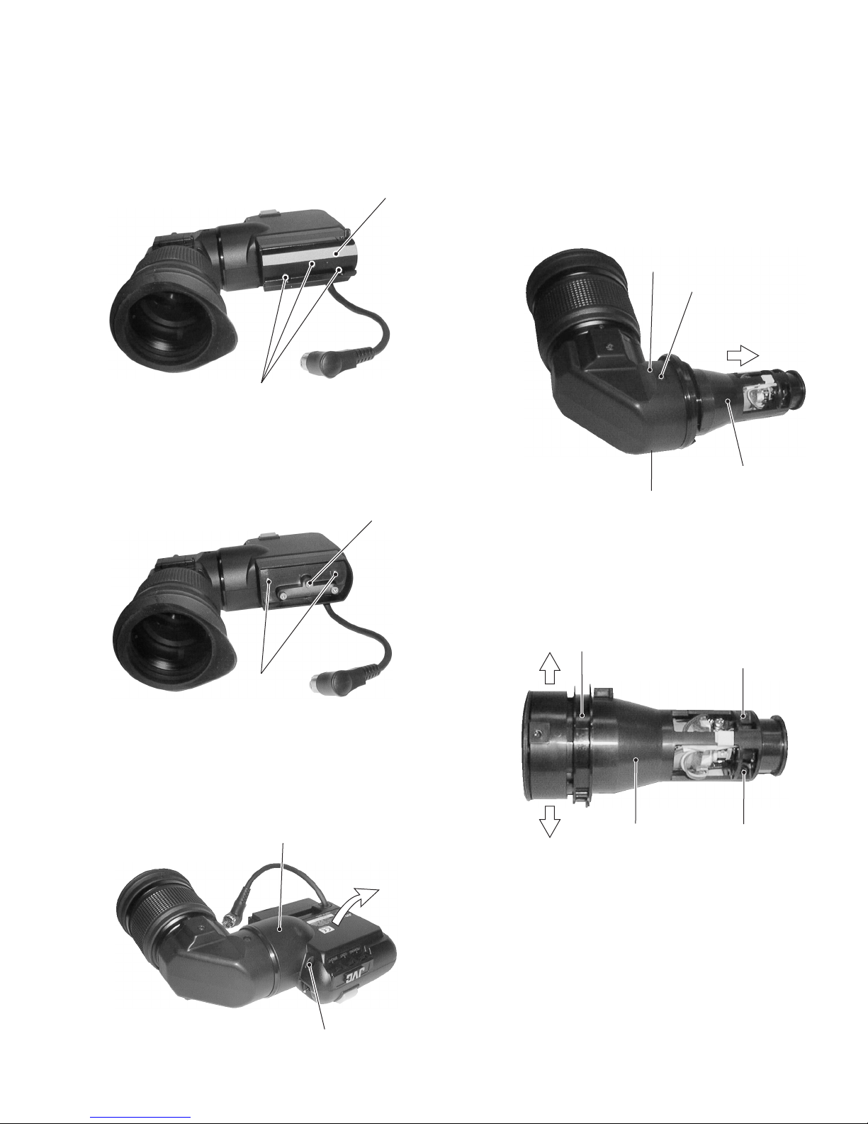
CONTROLS, INDICATORS AND
CONNECTORS
Tally ON/OFF switch
Set to OFF if you do not want to inform the people be-
ing shot that recording is on. However, the “REC”lamp
in the eyepiece will not turn off.
Tally Light
Lights when recording is in progress.
[BRIGHT] Brightness control
Adjusts the brightness of the viewfinder.
[CONT] Contrast control
Adjusts the contrast level of the viewfinder.
[PEAKING] Peaking(contour)control
Controls the level of viewfinder peaking.
Eyepiece
Ensures that ambient light does not reach the viewfinder
screen or falls into the eye of the cameraman.
The eyepiece can be opened to allow direct observa-
tion of the viewfinder screen.
Eyepiece fixing ring
Loosen this ring and move the eyepiece backward and
forward for diopter adjustment.
Stopper screw
Prevents the viewfinder from coming off the camera
head.
Mounting guide
Attaches to the camera’s viewfinder mount base.
Connector
Connector to connect the viewfinder to the camera
head.
[BATT] BATTERY LIGHT
This blinks when battery voltage becomes too low for
the camera to operate.
This lights when the battery has run out.
[REC/ALARM] LIGHT
This lights for these conditions.
Solid Grenn : While recording.
Blinks Green
: •While the VCR prerolls before
recording.
•If the Tape is finishing.
•If the VCR Malfunctions
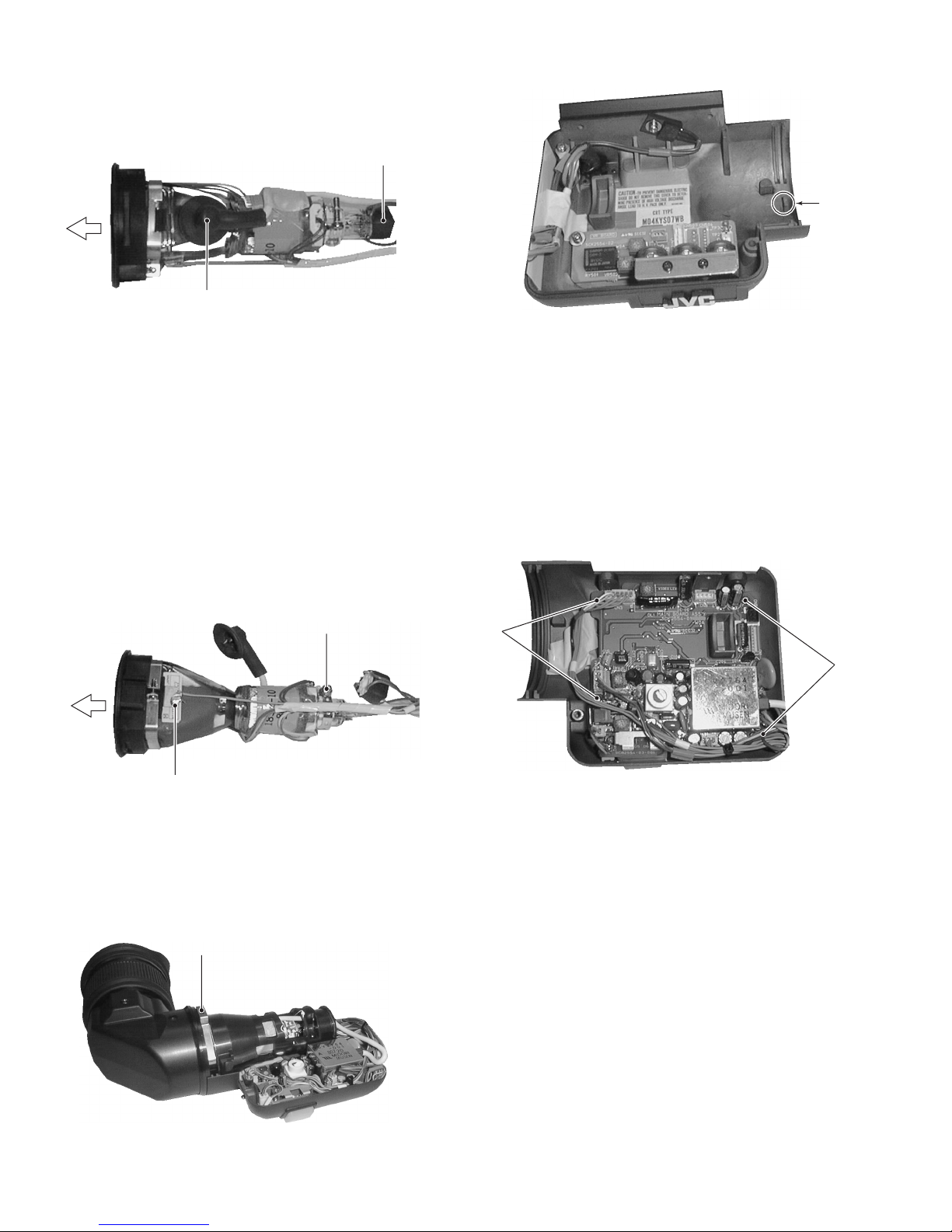
ATTACHING AND DETACHING
Attaching
1. Loosen the stopper screw.
2. Connect the cable.
3. Align the mounting guide with the camera’s viewfinder
mount base and attach the viewfinder.
4. Tighten the stopper screw.
5. Tighten the sliding securing ring.
* To detach the viewfinder, reverse the mounting proce-
dure.
1
2
3
4
5
6
7
8
9
10
3.
2.
5.
1.
4.
Viewfinder
mount base
Connector
Sliding securing ring
Stopper screw
Mounting
guide
11
1
2
10
7
8
9
6
21
3
4
5
BATT ALARM
REC
11 12

Service Manual
January. 1999
No. 60121
VIEWFINDER
MODEL
VF-P116WU
MODEL
VF-P116WE
VICTOR COMPANY OF JAPAN, LIMITED

Service Manual
No. 60121
VF-P116W
MODEL

䡵INSTRUCTIONS
1. DISASSEMBLY ................................................................................................................................................... 1
2. ELECTRICAL ADJUSTMENT .............................................................................................................................. 3
3. CHART AND DIAGRAM ..................................................................................................................................... 6
4. EXPLODED VIEW AND PARTS LIST .................................................................................................................. 8
5. ELECTRICAL PARTS LIST ................................................................................................................................ 10
6. REPACKING ...................................................................................................................................................... 12
TABLE OF CONTENTS
Section Title Page
COPYRIGHT © 1998 VICTOR COMPANY OF JAPAN, LTD.
Printed in Japan

SECTION 1
DISASSEMBLY
1.1 REMOVAL OF COVER
1. Remove three screws ˆand detach the slide base Å.
1.2 REMOVAL OF CRT
1. Open the bottom cover referring to “1.1 REMOVAL OF
COVER”.
2. Remove two screws 4from on the mirror case Îand pull
out the CRT together with the CRT holders ´from the mir-
ror case Î.
3. Remove one screw 3, and the bottom case Çcan be
opened in the direction of the arrow.
2. Remove two screws 2and detach the VF base ı.
Fig. 1-1
Fig. 1-2
Fig. 1-3
Fig. 1-4
Fig. 1-5
1
4. Remove two screws 5(one in the opposite side) and then
open the CRT holder ´. (See Fig.1-5)
3. Remove the ring Ïin the manner to open it.
1
Å
2
ı
3
Ç
´
Î
4
4
´
Ï
5
5

5. Remove the CRT socket ˝.
Fig. 1-10
When reassembling the CRT to the set, put the spring Ô
onto the pin on the bottom cover without fail.
Fig. 1-6
Fig. 1-8
Fig. 1-9
2
6. Shortcircuit the anode of the CRT to the chassis or the FBT
cover for discharge, and then disconnect the anode plug Ó.
Note: The anodic electrode is located inside the rubber
cover of the anode plug Ó. When discharging, be
careful not to get an electric shock.
7. Loosen one screw 6fixing the CRT to the deflection yoke
and remove the soldering ˆ.
Pull the CRT out of the deflection yoke in the direction of the
arrow (f).
1.3 REMOVAL OF MAIN BOARD
1. Open the bottom cover referring to “1.1 REMOVAL OF
COVER”.
2. Remove four screws 7and the MAIN board can be de-
tached.
Fig. 1-7
Ó
˝
ˆ
6
Ô
PIN
7
7

SECTION 2
ELECTRICAL ADJUSTMENT
2.1 ARTICLES REQUIRED FOR ADJUSTMENT
2.1.1 Measuring instruments necessary for adjustment
Oscilloscope
Frequency counter
Digital voltmeter
2.2 LOCATION OF ADJUSTMENT PARTS
VR board
MAIN board
2.1.2 Other necessities for adjustment
Camara and lens
Resolution chart or registration chart
Capable of measuring 10MHz or higher
bands, and calibrated
Readable in 8 or more digits.
Constancy of 0.1ppm/1 × 10-7 or more
at 0°C to 40°C
Input impedance of 10 M Ωor more,
and calibrated
Measuring instrument Requirement
V. HEIGHT
V. HEIGHT2
VR501
CN501
CN503 CN504 GND
TP3
TP2
CN101
CN102
RY501 VR502 PEAKING
VR102
CONTRAST
VR1
BRIGHT
VR8
VR3
H HOLD
VR5
H. LIN
CN401
CN6
CN7
CN1
CN5
V HOLD
CN2
CN4
TP1
CN8CN3
VIDEO LEVEL
VR101
VR7 VR6
SUB BRIGHT FOUCUS
3
•Adjustment by 4:3 mode

4
Measuring
Measuring point ( *)
No. Item instruments &
Adjustment parts ( -)
Adjustment procedure
Input signals
Adjustment level ( +)
1 12V supply
voltage check
•Digital voltmeter 1) Check to see if the specified voltage is meas-
ured at the measuring point.
*Between pin 5 of CN1 and
GND [MAIN]
++12V ±0.5V
2.3 CHECK OF SUPPLY VOLTAGE
1 H. HOLD
adjustment
•Frequency
counter
1) Adjust VR3 to obtain the specified frequency
at the measuring point.
*Between collector of Q10
[MAIN] and TP3(GND)[VR]
-H. HOLD(VR3)[MAIN]
+14.4 to 15kHz
2.4 ADJUSTMENT OF H.HOLD
1 V.HOLD
adjustment
•Oscilloscope
(V-rate,10:1)
1) Adjust Vr5 to obtain the specified level at the
measuring point.
*TP2 and TP3 (GND)[VR]
-V. HOLD(VR5)[MAIN]
+17 to 18ms(U.Ver)
+20.5 to 21.5ms(E.Ver)
2.5 ADJUSTMENT OF V.HOLD
1 Video level
adjustment
•Gray scale chart
•Oscilloscope
(H-rate,10:1)
1) Shoot the gray(scale) chart by the camera.
2) Observing the waveform on oscilloscope, ad-
just VR101 to obtain the specified level at the
measuring point.
*TP1[MAIN] and TP3
(GND)[VR]
-VIDEO LEVEL(VR101)
[MAIN]
++10 ±0.5V DC
2.6 ADJUSTMENT OF VIDEO LEVEL
17.5 ±0.5ms(U.Ver)
21 ±0.5ms(E.Ver)
+10 ±0.5V DC
0V DC

Measuring
Measuring point ( *)
No. Item instruments &
Adjustment parts ( -)
Adjustment procedure
Input signals
Adjustment level ( +)
Measuring
Measuring point ( *)
No. Item instruments &
Adjustment parts ( -)
Adjustment procedure
Input signals
Adjustment level ( +)
1 V. amplitude
adjustment
• Resolution chart or
Registration chart
1) Shoot the resolution chart or registration chart
so as to take the central circle of the chart as
large as possible.
2) Adjust the V. HIGHT control so that the central
circle of the chart shows a perfect circle.
3) If the central circle looks elliptical, fine adjust
the H.LIN control(L4) to correct it.
2.9 ADJUSTMENT OF V.AMPLITUDE (for 4:3)
1 Centering
adjustment
1) Set the BRIGHT and CONTRAST controls on
the front panel to the mechanical center posi-
tion respectively.
2.7 ADJUSTMENT OF CENTERING
-V. HEIGHT(VR501)[VR]-BRIGHT(VR8)[VR]
CONTRAST(VR1)[VR1]
1) Reduce the raster part by tuning the H.LIN and
V. HEIGHT controls.
-H. LIN(L4)[MAIN]
V. HEIGHT(VR4)[MAIN]
1) Adjust the DY centering magnet of the deflec-
tion yoke so as to position the raster part in
the center of the CRT.
-DY centering magnet
[Deflection yoke]
1 H. linearity
adjustment
• Resolution chart of
Registration chart
1) Shoot the resolution chart or registration chart
so as to take the central circle of the chart as
large as possible.
2) Adjust the H.LIN control so that the linearity of
the picture is aligned in both the sides.
2.8 ADJUSTMENT OF H.LINEARITY
-H. LIN(L4)[MAIN]
1 V.amplitude
adjustment
• Resolution chart or
Registration chart
1) Set to 16 : 9 mode.
2) Shoot the resolution chart or registration chart
so as to take the central circle of the chart as
large as possible.
3) Adjust the V.HIGHT control so that the central
circle of the chart shows a perfect circle.
4) If the central circle looks elliptical, fine adjust
the H.LIN control(L4) to correct it.
5) Return to 4 : 3 mode.
2.9 ADJUSTMENT OF V.AMPLITUDE (for 16:9)
-V. HEIGHT2(VR502)[VR]
1 Sub-brightness
adjustment
1) Set BRIGHT and PEAKING controls on the front
panel to the minimum position, while set the
CONTRAST control to the maximum position.
2) Adjust the SUB BRIGHT control so that the
raster is seen dimly.
2.10 ADJUSTMENT OF SUB-BRIGHTNESS
-SUB BRIHT(VR7)[MAIN]
1 Focus
adjustment
1) Shoot an object by the camera.
2) Set the CONTRAST and PEAKING controls on
the front panel to the mechanical center posi-
tion respectively.
3) Turn up and down the brightness with the
BRIGHT control on the front panel while ad-
justing the FOCUS control to obtain the best
focus.
2.11 ADJUSTMENT OF FOCUS
-FOCUS(VR6)[MAIN]
Raster part
CRT screen
Protecive glass of CRT
Fluorescent screen of CRT
55

CHARTS AND DIAGRAM
SECTION 3
3.1
66
UNLESS OTHERWISE SPECIFIED
RESISTORS : 1/10W
PNP TRANSISTORS
NPN TRANSISTORS
: NOT MOUNTEDMARKED PARTS
: MSA1022(C)
: MSC2295(C)
Voltage and waveform weasurements.
・Voltage : Measured with digital volt meter
・Waveform : camera color bars.
in DC range, iris closed.
VIDEO OUTPUT
chasiss GND
3.0
22.6
5.0
8.4
-0.2
21.4
44.6
21.9
4.4
2.2
1.5
2.4
2.3
5.0
2.4
1.9
5.0
1.6
2.0
4.4
4.0
0.7
5.0
-0.2
0
0
8.9 0
967
57.3
57.3
382V
6.8
3.7
0.7
-2.0
0.3
7.24.5
1.2
1.7
5.0
9.0
0
0
0.1
20.8
21.2
21.4
3.3
3.9
3.9
4.7
5.5
4.7
6.3
5.1
6.3
4.7
5.5
6.3
6.2
5.5
5.4
6.1
9.8
0
Blanking
High voltage
H-drive
V-drive
Protector
Pluse shapper
Clamp
Peaking
Sync separator
VIDEO INPUT
(CN1 3PIN)
IC2 16PIN
4.2Vp-p
(H-rate)
IC2 3PIN
1.9Vp-p
(V-rate)
IC2 1PIN
1.7Vp-p
(V-rate)
Q109 COLLECTOR
21.5Vp-p
(H-rate)
TP1
9.4Vp-p
(H-rate)
T1 2PIN
0.26Vp-p
(H-rate)T1 5PIN
140Vp-p
(H-rate)
IC101 5PIN
4.8Vp-p
(H-rate)
VF-P116(A) SCHEMATIC DIAGRAM

C109 C133
C107
C10
C114
C19
CN7
C214
C111
C17
CN6
TP1
G
C108
3
6
SIDE B
SIDE B SIDE B
MAIN BOARD
VR BOARD TOPTALLY BOARD
CIRCUIT BOARDS3.2
77
R601
1C(両面)
This manual suits for next models
6
Table of contents
Other JVC Camera Accessories manuals

JVC
JVC KA-551U User manual

JVC
JVC TRAVEL POUCH INSTRUCTIONS KAMERA-TASCHE GEBRAUCHSANLEITUNG ETUI DE TRANSPORT INSTRUCTIONS... User manual

JVC
JVC WR-MG200U User manual

JVC
JVC GR DVP 1 User manual

JVC
JVC CARRYING BAG CB-V77U User manual

JVC
JVC Studio Kit KA-F5602U User manual

JVC
JVC KA-C76 User manual

JVC
JVC FS-900 User manual

JVC
JVC CB-A260 User manual

JVC
JVC GY-HM750U User manual