99
S4 QYSDSP2005Z SCREW M2 x 5
S6 QYSPSA2006M SCREW M2 x 6
S7 QYSDSP2006M SCREW M2 x 6
S8 QYSSSPT2030M SCREW M2 x 3.0
S9 QYSPSPD2608Z SCREW M2.6 x 8
S10 QYSDSP2606M SCREW M2.6 x 6
S11 QYSPSPT2040M SCREW M2 x 4.0
S12 QYSPSP2615Z SCREW M2.6 x 15
S13 QYSPSPT2030M SCREW M2 x 3.0
S14 QYSSSP2606M SCREW M2.6 x 2.6
S15 QYSPSPT2025M SCREW M2 x 2.5
S16 QYSDSP2610M SCREW M2.6 x 10
S17 QYSPSPD2605Z SCREW M2.6 x 5
S18 QYSPSP2003Z SCREW M2 x 3
S19 QYSPSPL2605Z SCREW M2.6 x 5
S20 QYSDSP2608M SCREW M2.6 x 8
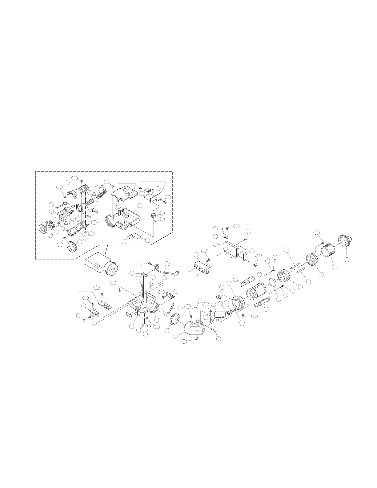
1 SC31312-012 CRT HOLDER1
2 SC31312-011 CRT HOLDER
!3 SCV1273-001 CRT SOCKET
!4 SCV1852-10A DEFLECTION YOKE
!5 M04KYS07WB PICTURE TUBE
6 SC43463-001 BRACKET
7 TLG102A LED GREEN
8 TLR102A LED RED
9 SC40909-001 BRACKET
10 SC31314-013 CRT MASK
11 SC43615-013 CRT PLATE
12 SC44495-001 RING
13 SC43468-001 CUSHION
14 SC46364-001 TALLY BRACKET
15 SC20430-012 UPPER CASE
16 SC20431-004 BOTTOM CASE
17 SC46070-001 VR BRACKET
18 SC44724-003 VR KNOB
19 SC44729-011 CLAMP BASE
20 SCV2801-00B VF CABLE ASSEMBLY
21 SC44975-001 LABEL
22 SC46020-001 CRT LABEL
23 SC41663-001 CAUTION LABEL
24 AN7709F I.C.(M) MATSUSHITA
25 SC46304-001 SPRING
26 SC46019-002 SPACER
27 SC20336-011 MIRROR CASE
28 SC43459-002 PIN
29 SC43460-002 BRACKET
30 SC46045-001 MIRROR
31 SC43462-001 MIRROR HOLDER
32 SC43614-001 HOLDER PLATE
33 SC43491-002 SPRING
34 SC31041-013 HOLDER
35 SC31889-002 EYE FRAME
36 SC31890-001 CAMERA HOLDER
37 SC42475-001 LENS
38 SC40465-020 STEEL BALL
39 SC46021-001 SPRING
40 SC31888-001 LENS HOLDER
41 SC44736-041 SHAFT
42 SC45702-002 FRONT RING
43 SC43164-001 RING
44 SC31337-001 EYE CAP
45 SC31891-001-K VF BASE
46 SC31339-021 SLIDE BASE
47 SC44680-001 PLATE
48 SC44679-001 PLATE
49 SC44678-002 STOPPER PIN
50 SC41737-011 LABEL for U model
51 SC42594-001 LABEL for U model
52 SC45925-001 LABEL for E model
53 SC45909-070 TUBE
54 SC32217-001 TALLY COVER
55 SC46425-001 LABEL
56 QZL1001-012 UL LABEL
N1 QYNNS2600N NUT
S1 QYSBSF2608M SCREW M2.6 x 8
S2 QYSPSP2008Z SCREW M2 x 8
S3 QYSPSPL2605Z SCREW M2.6 x 5
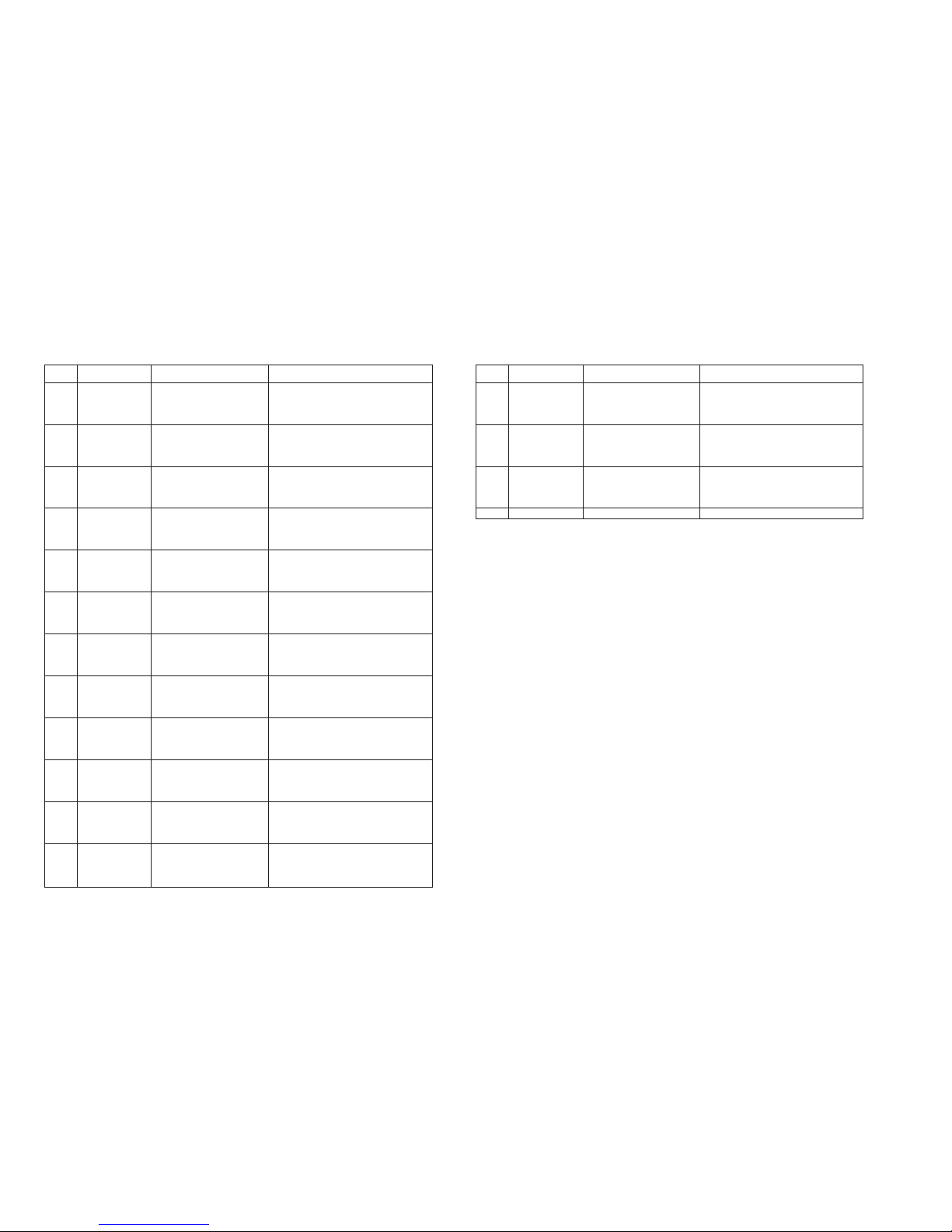
DescriptionPart No. Part Name
Symbol
No.
VF-P116(A) ASSEMBLY PARTS LIST M1 M1MM````
DescriptionPart No. Part Name
Symbol
No.