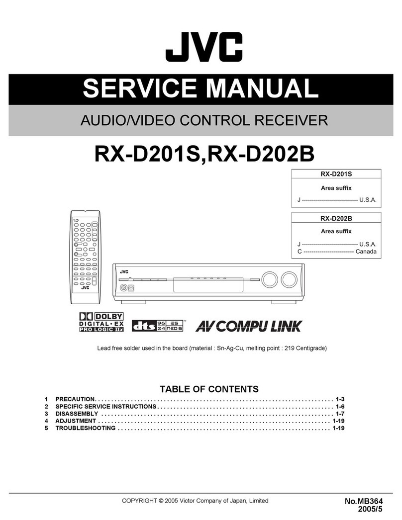
JVC RX-D212BJ User manual

SERVICE MANUAL
COPYRIGHT © 2006 Victor Company of Japan, Limited No.MB525
2006/5
AUDIO/VIDEO CONTROL RECEIVER
MB52520065
RX-D211SJ,RX-D212BJ,
RX-D212BC
Lead free solder used in the board (material : Sn-Ag-Cu, melting point : 219 Centigrade)
TABLE OF CONTENTS
1 PRECAUTION. . . . . . . . . . . . . . . . . . . . . . . . . . . . . . . . . . . . . . . . . . . . . . . . . . . . . . . . . . . . . . . . . . . . . . . . . 1-3
2 SPECIFIC SERVICE INSTRUCTIONS . . . . . . . . . . . . . . . . . . . . . . . . . . . . . . . . . . . . . . . . . . . . . . . . . . . . . . 1-5
3 DISASSEMBLY . . . . . . . . . . . . . . . . . . . . . . . . . . . . . . . . . . . . . . . . . . . . . . . . . . . . . . . . . . . . . . . . . . . . . . . 1-6
4 ADJUSTMENT . . . . . . . . . . . . . . . . . . . . . . . . . . . . . . . . . . . . . . . . . . . . . . . . . . . . . . . . . . . . . . . . . . . . . . . 1-14
5 TROUBLESHOOTING . . . . . . . . . . . . . . . . . . . . . . . . . . . . . . . . . . . . . . . . . . . . . . . . . . . . . . . . . . . . . . . . . 1-15

1-2 (No.MB525)
SPECIFICATION
* Corresponding to Linear PCM, Dolby Digital, and DTS (with sampling frequency -32 kHz, 44.1 kHz, 48 kHz).
Designs and specifications are subject to change without notice.
Amplifier
Output Power At stereo operation Front channels 110 W per channel, min. RMS, driven into 6 Ωat
20 Hz to 20 kHz with no more than 0.8% total har-
monic distortion.
At surround operation Front channels 110 W per channel, min. RMS, driven into 6 Ωat
1 kHz with no more than 0.8% total harmonic dis-
tortion.
Center channel 110 W, min. RMS, driven into 6 Ωat 1 kHz, with
no more than 0.8% total harmonic distortion.
Surround channels 110 W per channel, min. RMS, driven into 6 Ωat
1 kHz, with no more than 0.8% total harmonic dis-
tortion.
Surround back channels 110 W per channel, min. RMS, driven into 6 Ωat
1 kHz, with no more than 0.8% total harmonic dis-
tortion.
Audio Audio Input Sensitivity/Impedance DVR/DVD, VCR, DBS, TV 300 mV/47 kΩ
Audio Input (DIGITAL IN)* Coaxial: DIGITAL IN 1(DVR/DVD) 0.5 V(p-p)/75 Ω
Optical: DIGITAL IN 2(DBS), 3(VCR) -21 dBm to -15 dBm (660 nm ±30 nm)
USB USB DIGITAL
Audio Output Level DVR, VCR 300 mV
Signal-to-Noise Ratio ('66 IHF/'78 IHF) 80 dB/70 dB
Frequency Response (6 Ω) 20 Hz to 20 kHz (±1 dB)
Bass Boost +4 dB ±1 dB at 100 Hz
Equalization (at DSP operation) Center frequency 63 Hz, 250 Hz, 1 kHz, 4 kHz, 16 kHz
Control range ±8 dB
Video Video Input Sensitivity/Impedance Composite video: DVR/DVD, VCR, DBS 1 V(p-p)/75 Ω
S-video: DVR/DVD, VCR, DBS Y (luminance) : 1 V(p-p)/75 Ω
C (chrominance, burst) : 0.286 V(p-p)/75 Ω
Component: DVR/DVD, VCR (DBS) Y (luminance) : 1 V(p-p)/75 Ω
PB, PR : 0.7 V(p-p)/75 Ω
Video Output Level/Impedance Composite video: DVR, VCR, MONITOR OUT 1 V(p-p)/75 Ω
S-video: DVR, VCR, MONITOR OUT Y (luminance) : 1 V(p-p)/75 Ω
C (chrominance, burst) : 0.286 V(p-p)/75 Ω
Component: MONITOR OUT Y (luminance) : 1 V(p-p)/75 Ω
PB, PR : 0.7 V(p-p)/75 Ω
Synchronization Negative
FM tuner (IHF)
Tuning Range 87.5 MHz to 108.0 MHz
Usable Sensitivity Monaural 12.8 dBf (1.2 µV/75 Ω)
50 dB Quieting Sensitivity Monaural 16.0 dBf (1.7 µV/75 Ω)
Stereo 37.5 dBf (20.5 µV/75 Ω)
Stereo Separation at REC OUT 35 dB at 1 kHz
AM tuner
Tuning Range 530 kHz to 1 710 kHz
General
Power Requirements AC 120 V , 60 Hz
Power Consumption 150 W/200 VA (at operation)
0.9 W (in standby mode)
Dimensions (W ×H ×D) 435 mm ×91.5 mm ×360 mm
(17 3/16 inches ×3 5/8 inches ×14 3/16 inches)
Mass 6.7 kg (14.8 lbs)

(No.MB525)1-3
SECTION 1
PRECAUTION
1.1 Safety Precautions
(1) This design of this product contains special hardware and
many circuits and components specially for safety purpos-
es. For continued protection, no changes should be made
to the original design unless authorized in writing by the
manufacturer. Replacement parts must be identical to
those used in the original circuits. Services should be per-
formed by qualified personnel only.
(2) Alterations of the design or circuitry of the product should
not be made. Any design alterations of the product should
not be made. Any design alterations or additions will void
the manufacturers warranty and will further relieve the
manufacture of responsibility for personal injury or property
damage resulting therefrom.
(3) Many electrical and mechanical parts in the products have
special safety-related characteristics. These characteris-
tics are often not evident from visual inspection nor can the
protection afforded by them necessarily be obtained by us-
ing replacement components rated for higher voltage, watt-
age, etc. Replacement parts which have these special
safety characteristics are identified in the Parts List of Ser-
vice Manual. Electrical components having such features
are identified by shading on the schematics and by ( ) on
the Parts List in the Service Manual. The use of a substitute
replacement which does not have the same safety charac-
teristics as the recommended replacement parts shown in
the Parts List of Service Manual may create shock, fire, or
other hazards.
(4) The leads in the products are routed and dressed with ties,
clamps, tubings, barriers and the like to be separated from
live parts, high temperature parts, moving parts and/or
sharp edges for the prevention of electric shock and fire
hazard. When service is required, the original lead routing
and dress should be observed, and it should be confirmed
that they have been returned to normal, after reassem-
bling.
(5) Leakage shock hazard testing
After reassembling the product, always perform an isola-
tion check on the exposed metal parts of the product (an-
tenna terminals, knobs, metal cabinet, screw heads,
headphone jack, control shafts, etc.) to be sure the product
is safe to operate without danger of electrical shock.Do not
use a line isolation transformer during this check.
• Plug the AC line cord directly into the AC outlet. Using a
"Leakage Current Tester", measure the leakage current
from each exposed metal parts of the cabinet, particular-
ly any exposed metal part having a return path to the
chassis, to a known good earth ground. Any leakage cur-
rent must not exceed 0.5mA AC (r.m.s.).
• Alternate check method
Plug the AC line cord directly into the AC outlet. Use an
AC voltmeter having, 1,000Ωper volt or more sensitivity
in the following manner. Connect a 1,500Ω10W resistor
paralleled by a 0.15µF AC-type capacitor between an ex-
posed metal part and a known good earth ground.
Measure the AC voltage across the resistor with the AC
voltmeter.
Move the resistor connection to each exposed metal
part, particularly any exposed metal part having a return
path to the chassis, and measure the AC voltage across
the resistor. Now, reverse the plug in the AC outlet and
repeat each measurement. Voltage measured any must
not exceed 0.75 V AC (r.m.s.). This corresponds to 0.5
mA AC (r.m.s.).
1.2 Warning
(1) This equipment has been designed and manufactured to
meet international safety standards.
(2) It is the legal responsibility of the repairer to ensure that
these safety standards are maintained.
(3) Repairs must be made in accordance with the relevant
safety standards.
(4) It is essential that safety critical components are replaced
by approved parts.
(5) If mains voltage selector is provided, check setting for local
voltage.
1.3 Caution
Burrs formed during molding may be left over on some parts
of the chassis.
Therefore, pay attention to such burrs in the case of pre-
forming repair of this system.
1.4 Critical parts for safety
In regard with component parts appearing on the silk-screen
printed side (parts side) of the PWB diagrams, the parts that are
printed over with black such as the resistor ( ), diode ( )
and ICP ( ) or identified by the " " mark nearby are critical
for safety. When replacing them, be sure to use the parts of the
same type and rating as specified by the manufacturer.
(This regulation dose not Except the J and C version)
Good earth ground
Place this
probe on
each exposed
metal part.
AC VOLTMETER
(Having 1000
ohms/volts,
or more sensitivity)
1500 10W
0.15 F AC TYPE
1-4 (No.MB525)
1.5 Importance admistering point on the safety
FC103
CN120
C1001
R1002
RY101
B152
C1003
FC113
R1001
EP151
B142
D103
C101
D107
Q101
R106
R104
B102
R105
R101
D108
D104
D101
C104
R102
D102
R103
FW121
L101
CN202
B104
C1004
CN121
FC114 FC104
C1002
B143
B144
EP152
B101
B181
C1005
C102
B103
B151
B141
T102
B145
R187
D120
R152
FC101
D119
C113
R153
R188
R166
D115
TH274
R190
C156
R165
CN102
Q103
TH101
R189
C114
FC111
CN122
R167
R107
C159
D112
C169
IC151
D114
D162
C166
C112
D161
D109
C111
R158
C110
EP102
IC152
R151
C108
IC153
IC154
C109
C151
Q102
C154
C165
FC112
D113
D111
CN106
FC102
R108
C152
D110
Q171
FW104
B2661
FW116
FW117
HS171
HS153
HS154
HS151
HS152
B2673
B2699
B2698
B2697
B2696
B2671
B2701
B2711
B2692
B2691
B2664
B2663
B2681
B2685
B2694
B2721
B2682
B2683
B2684
B2662
B2693
B2672
B2702
B2665
B2674
B2700
B2666
W101
W102
Graphic symbol mark
(This symbol means fast blow type fuse.)
FOR CONTINUED PROTECTION AGAINST RISK
OF FIRE, REPLACE ONLY WITH SAME TYPE
AND RATING OF FUSES ;
should be read as follows ;
F101 : 2A 125V
F102 : 2A 125V
F103 : 6.3A 125V
F101 : 2A 125V
F102 : 2A 125V
F103 : 6.3A 125V
Full Fuse Replacement Marking
FUSE CAUTION
Le symbole graphique (Ce symbole signifie
fusible de type a fusion rapide.)
POUR UNE PROTECTION CONTINUE CONTRE
DES RISQUES D'INCENDIE, REMPLACER
SEULEMENT PAR UN FUSIBLE DU MEME TYPE ;
Marquage Pour Le Remplacement
Complet De Fusible
PRECAUTIONS SUR LES FUSIBLES
doit etre interprete comme suit ;
^

(No.MB525)1-5
SECTION 2
SPECIFIC SERVICE INSTRUCTIONS
This service manual does not describe SPECIFIC SERVICE INSTRUCTIONS.

1-6 (No.MB525)
SECTION 3
DISASSEMBLY
3.1 Main body section
3.1.1 Removing the top cover
(See Figs.1 and 2)
(1) From the both sides of the main body, remove the four
screws Aattaching the top cover. (See Fig.1)
(2) From the back side of the main body, remove the six
screws Battaching the top cover. (See Fig.2)
(3) Remove the top cover in the direction of the arrow. (See
Fig.1)
Fig.1
3.1.2 Removing the tuner
(See Fig.3)
• Remove the top cover.
(1) From the top side of the main body, disconnect the card
wire from the connector CN1 on the tuner.
(2) From the back side of the main body, remove the two
screws Cattaching the tuner to the rear panel and then
take out the tuner.
3.1.3 Removing the XM board
(See Fig.3)
• Remove the top cover.
Reference:
Remove the tie band bundling the wires.
(1) From the back side of the main body, remove the two
screws Dfrom the rear panel.
(2) From the top side of the main body, disconnect the wire
from the connector CN662 on the DSP board.
(3) Disconnect the card wire from the connector CN538 on the
XM board.
(4) Take out the XM board from the main body.
Fig.3
A
Top cover
D C
TunerDSP board XM board
CN1
CN662 CN538
Rear panel

(No.MB525)1-7
3.1.4 Removing the fan motor
(See Fig.4)
• Remove the top cover.
Reference:
Remove the tie band bundling the wires.
(1) From the top side of the main body, disconnect the wire
from the connector CN103 on the main amplifier board.
(2) Remove the three screws Eand take out the fan motor as-
sembly.
(3) Remove the two screws Fattaching the fan motor to the fan
bracket.
3.1.5 Removing the AV compulink board
(See Fig.4)
• Remove the top cover.
(1) From the top side of the main body, disconnect the wire
from the connector CN531 on the AV compulink board.
(2) From the back side of the main body, remove the screw G
and take out the AV compulink board.
Fig.4
3.1.6 Removing the rear panel
(See Fig.5)
• Remove the top cover, tuner, XM board and AV compulink
board.
(1) From the back side of the main body, remove the strain re-
lief from the rear panel in the direction of the arrow and re-
move the power cord.
(2) Remove the twenty two screws Hattaching the rear panel.
(3) Take out the rear panel from the main body.
Fig.5
Fan motor
F
F
G
Rear panel
CN531
AV compulink board
Fan motor
CN103
Main amplifier boardFan bracket
E
Strain relief
H
Rear panel
Power cord HH

1-8 (No.MB525)
3.1.7 Removing the DSP board
(See Fig.6)
• Remove the top cover, tuner, XM board, AV compulink board
and rear panel.
(1) From the top side of the main body, remove the screw Jat-
taching the DSP board.
(2) Disconnect the connectors (CN661, CN683) on the DSP
board from the volume board.
Note:
When removing the DSP board, take care not to break
the claw of the connector on it.
(3) Take out the DSP board and disconnect the wires from the
connector CN681 on the forward side of the DSP board.
(4) Take out the DSP board from the main body.
3.1.8 Removing the video board
(See Fig.6)
• Remove the top cover, tuner, XM board, AV compulink board
and rear panel.
(1) From the top side of the main body, disconnect the wire
from the connector CN533 on the video board.
(2) Disconnect the connector CN525 on the video board from
the connect board.
(3) Take out the video board from the main body.
Fig.6
3.1.9 Removing the speaker terminal 1 and 2 board
(See Fig.7)
• Remove the top cover, tuner, XM board, AV compulink board
and rear panel.
(1) From the top side of the main body, disconnect the wires
from the connectors (CN261, CN461) on the speaker ter-
minal 1 board.
(2) Disconnect the wires from the connectors (CN205, CN262,
CN263) on the speaker terminal 2 board.
(3) Take out the speaker terminal 1 and 2 board from the main
body.
Fig.7
3.1.10 Removing the power transformer
(See Fig.8)
• Remove the top cover.
Reference:
Remove the tie bands bundling the wires.
(1) From the top side of the main body, disconnect the wires
from the connector CN121 on the primary board.
(2) Disconnect the wires from the connector CN106 on the
regulator board.
(3) Disconnect the wires from the connector CN111 on the
main amplifier board.
(4) Remove the four screws Kand take out the power trans-
former from the main body.
Fig.8
CN533
CN525
Video board CN681
DSP board
Volume board
Connect board
CN661
CN683
J
CN263
CN261
CN461
CN205
CN262
Speaker terminal 2 board Speaker terminal 1 board
CN111
CN106
Power transformer
Primary board
Regulator board Main amplifier board
K
CN121

(No.MB525)1-9
3.1.11 Removing the primary board
(See Fig.9)
• Remove the top cover.
Reference:
Remove the tie band bundling the wires.
(1) From the top side of the main board, remove the wires from
the connectors (CN120, CN121) on the primary board.
(2) Disconnect the wires from the connector CN102 on the
regulator board.
(3) Remove the two screws Mattaching the primary board.
(4) Take out the primary board from the main body.
3.1.12 Removing the regulator board
(See Fig.9)
• Remove the top cover and video board.
Reference:
Remove the tie band bundling the wires.
(1) From the top side of the main board, remove the wires from
the connectors (CN106, CN102, CN122) on the regulator
board.
(2) Disconnect the wires from the connectors (CN506, CN507)
on the input board.
(3) Disconnect the wire from the connector CN105 on the main
amplifier board.
(4) Remove the four screws Nattaching the regulator board.
(5) Take out the regulator board from the main body.
Fig.9
CN120
CN122
CN106
CN102
CN506
CN507
Main amplifier board
Input board
Primary board
M
N
N
N
M
CN121
CN111
CN105
Regulator board

1-10 (No.MB525)
3.1.13 Removing the volume board
(See Fig.10)
• Remove the top cover, tuner, XM board, AV compulink board,
rear panel, DSP board and video board.
(1) From the top side of the main body, disconnect the connec-
tor CN413 on the main amplifier board from the volume
board.
(2) Disconnect the connector CN503 on the input board from
the volume board and then take out the volume board in an
upward direction.
Note:
When removing the volume board, take care not to break the
claws of the connectors on the main amplifier board and input
board.
3.1.14 Removing the connect board
(See Fig.10)
• Remove the top cover, tuner, XM board, AV compulink board,
rear panel, DSP board and video board.
(1) From the top side of the main body, disconnect the connec-
tor CN524 on the input board from the connect board.
(2) Take out the connect board in an upward direction.
Note:
When removing the connect board, take care not to break the
claws of the connectors on the input board.
3.1.15 Removing the input board
(See Fig.10)
• Remove the top cover, tuner, XM board, AV compulink board,
rear panel, DSP board, video board and volume board.
Reference:
Remove the tie band bundling the wires.
(1) From the top side of the main body, disconnect the wires
from the connectors (CN506, CN507, CN508, CN509) on
the input board.
(2) Disconnect the wire from the connector CN205 on the
speaker terminal 2 board.
(3) Remove the three screws Pand take out the input board
from the main body.
Fig.10
CN524
CN507
CN506
CN509
CN508
CN503
CN413
Input board
Speaker terminal
2 board
PP
CN205
P
Connect board Volume board

(No.MB525)1-11
3.1.16 Removing the main amplifier board
(See Figs.11 and 12)
• Remove the top cover, tuner, XM board, AV compulink board,
rear panel, DSP board, video board and volume board.
(1) From the top side of the main body, disconnect the wires
from the connectors (CN261, CN262, CN263) on the
speaker terminal 1 and 2 board. (See Fig.11)
Reference:
Remove the tie bands bundling the wires.
(2) Disconnect the wires from the connectors (CN105, CN111)
on the main amplifier board. (See Fig.11)
(3) Disconnect the wire from the connector CN509 on the input
board. (See Fig.11)
(4) Disconnect the wires from the connectors (CN911, CN921)
on the front input board. (See Fig.11)
(5) Remove the two screws Qand four screws Rattaching the
main amplifier board. (See Fig.12)
(6) Take out the main amplifier board with the regulator board
from the main body. (See Fig.12)
3.1.17 Removing the regulator board
(See Fig.12)
• Remove the top cover.
(1) From the top side of the main amplifier board, disconnect
the wire from the connector CN204 on the main amplifier
board.
(2) Remove the two screws Sattaching the regulator board
from the heat sink.
Fig.11
Fig.12
Input board
Front input board
CN111
CN921
CN911
CN105
CN509
CN261
CN262,CN263
Speaker terminal 2 board
Speaker terminal 1 board
Main amplifier board
Regulator board
CN204
R
Q
SS
Q
Main amplifier board

1-12 (No.MB525)
3.1.18 Removing the heat sink
(See Fig.13)
• Remove the top cover, tuner, XM board, AV compulink board,
rear panel, DSP board, video board, volume board and main
amplifier board.
From the forward side of the main amplifier board, remove the
two screws Tand remove the heat sink.
Fig.13
3.1.19 Removing the front panel assembly
(See Figs.14 and 15)
• Remove the top cover.
Reference:
Remove the tie bands and wire holder bundling the wires.
(1) From the top side of the main body, disconnect the card
wire from the connector CN102 on the regulator board.
(See Fig.14)
(2) Disconnect the wire from the connector CN508 on the input
board. (See Fig.14)
(3) Remove the two screws Uand three screws Vattaching
the front panel assembly. (See Fig.14)
(4) Disconnect the wires from the connectors (CN911, CN921)
on the front input board. (See Fig.14)
(5) From the bottom side of the main body, remove the four
screws Wattaching the front panel assembly. (See Fig.15)
(6) Release the joints aand remove the front panel assembly
in the direction of the arrow. (See Fig.15)
Fig.14
Fig.15
Heat sink
T
Main amplifier board
T
V
VU
Front panel assembly
CN508
CN921
CN911
CN102 Input board
Front input board
Regulator board
W
Front panel assembly
W
a

(No.MB525)1-13
3.1.20 Removing the front input board
(See Fig.16)
• Remove the top cover and front panel assembly.
From the inside of the front panel assembly, remove the two
screws Xattaching the front input board.
3.1.21 Removing the JOG board
(See Figs.16 and 17)
• Remove the top cover and front panel assembly.
(1) From the inside of the front panel assembly, remove the
four screws Yattaching the JOG board. (See Fig.16.)
(2) Take out the JOG board while lifting it from the front panel
assembly little by little.
Reference:
The rotary knobs are removed from the front side simul-
taneously. (See Fig.17)
(3) From the forward side of the JOG board, disconnect the
wire from the connector CN913. (See Fig.16)
Fig.16
Fig.17
3.1.22 Removing the FL board
(See Fig.18)
• Remove the top cover, front panel assembly and JOG board.
From the inside of the front panel assembly, remove the eight
screws Zand take out the FL board.
Fig.18
CN913
Y
Y
Y
Front panel assembly
FL board
X
Front input board
JOG board
Front panel assembly
Rotary knob
Z
Z
Front panel assembly
FL board
Z
Z

1-14 (No.MB525)
SECTION 4
ADJUSTMENT
This service manual does not describe ADJUSTMENT.

(No.MB525)1-15
SECTION 5
TROUBLESHOOTING
This service manual does not describe TROUBLESHOOTING.

(No.MB525)
Audio/Video Systems Category 10-1,1chome,Ohwatari-machi,Maebashi-city,371-8543,Japan
Victor Company of Japan, Limited
VPT
Printed in Japan

SCHEMATIC DIAGRAMS
RX-D211SJ,RX-D212BJ,RX-D212BC
Contents
Block diagrams
Standard schematic diagrams
Printed circuit boards
2-1
2-2
2-12 to 17
CD-ROM No.SML200605
AUDIO/VIDEO CONTROL RECEIVER
No.MB525SCH
2006/5
COPYRIGHT 2006 Victor Company of Japan, Limited.
Lead free solder used in the board (material : Sn-Ag-Cu, melting point : 219 Centigrade)

In regard with component parts appearing on the silk-screen printed side (parts side) of the PWB diagrams, the
parts that are printed over with black such as the resistor ( ), diode ( ) and ICP ( ) or identified by the " "
mark nearby are critical for safety.

2-1
Block diagram
CN253
CN254
DSP_STATUS
DSP_READY
DSP_CLOCK
DSP_RESET
DSP_COMMAND
MOSI
MISO
SS,HREQ
DSP_RST
GPIO1 to 4
IC673
INV
SCK
MICK
LIN+/-
RIN+/-
IC611 to IC613
IC615
IC621,IC622
IC632 to IC634
IC651,IC652
AMP.
C_LRCK, S_LRCK
C_BCK, S_BCK
D/A0 to 3, DATA
A1+/- to A4+/-
B1+/- to B4+/-
DSP and digital signal input terminal section
Component Video signal
input/output section
CDIN
CDOUT
CCLK
D_CS
D_RST
DSP_L/R
DSP_SL
DSP_SR
DSP_C
DSP_SW
DSP_SBL
DSP_SBR
DSP_L/R
DSP_SL/SR
DSP_C
DSP_SW
DSP_IN_L
DSP_IN_R
VCR IN
DVR/DVD IN
MONITOR
COMPONENT
VIDEO IN/OUT
J4501
DIGITAL IN1
J681
RX0
RX1
RX2
RX4(USB_IN)
RX5
(DIT_TX) D_RST
(DITRST)
IC671
CPU
IC667
8CH
CODEC IC511
6CH
VOLUME
Q1501
to
Q1505
Q1507
to
Q1509
MUTE
IC513
Q1551,Q1561
LEVEL DETECT
IC512
AUDIO SOUND
PROCESSOR
IC661
DSP
IC505
Q511
RESET
IC662,X661
24.576MHz
X671
6.14MHz
IC601
AMP.
XM Radio
section
COMM_RX_M/P
COMM_TX_M/P
XM_TX, XM_RX
XM_RESET
XM_ANT_ON
I2C_CLK
I2C_LRCK
I2S_DA
I2S_OCLK
TV_L/R
DBS_L/R
VCRREC_L/R
VCR_L/R
DVRREC_L/R
DVR_L/R
SW_OUT
DBS_S/CIN
VCR_S/CIN
DVR_S/CIN
SBWR_MUTE
IC991
XM RADIO
RECEIVER
IC502
6CH
SW
Q501,Q510
SW MUTE
Q503 to Q505
L/R ATT.
Q507 to Q509
TU MUTE
IC501
CPU
XTAL
IC503
AMP
Volume section Degital pwoer amplifier & PWM modulator section
Regulator section
DSP-SBL
DSP-SBR
SBLOUT
SBROUT
L OUT
R OUT
SL OUT
SR OUT
C OUT
BD_CL
BD_DA
FL, FR
FL
FR
SW_OUT
S_MUTE
IN_LEV1
IN_LEV2
SBWFR OUT
FRONT_L
FRONT_R
SL, SR, C
SBL, SBR
IC573
IC576
PR SEL.
IC572
IC575
PB SEL.
IC571
IC574
Y SEL.
IC552,IC553
SC IN SEL.
Q5511 to Q5520
VCR/DVR OUT SEL.
IC551
SY IN SEL.
IC554
CV IN SEL.
IC565
CROMA DECODER
IC561
Y/C SEPA.
IC564
CLOCK
GEN.
IC562
SC SEL.
IC563
SY SEL.
TA/TC_SDA
TA/TC_SCL
TA/TC_SDA
TA/TC_SCL
V_CONT6
V_CONT7
SY
SY
Y/G OUT
B-Y/B OUT
R-Y/R OUT
YOUT
PBOUT
PBIN1
PBIN2
PROUT
PRIN1
PRIN2
YIN1
YIN2
SC
SC
CV
CV
CV, SY_OUT,SC_OUT
V_CONT7
V_CONT6
V_CONT1, V_CONT8
V_CONT1
V_CONT8
V_CONT1
V_CONT2
V_CONT1
V_CONT4
YOUTCOUT
SC_OUT SY_OUT
AUDIO IN/OUT
TV
DBS
J501
TU_L/R
BD_CL
BD_DA
INH
RESET
IC504
EEPROM
RC_SDA
RC_SCL
RC_WP
L_OUT, R_OUT
INPUT_ATT
S_MUTE
IN_LEV1
IN_LEV2
T_MUTE
TU_CE, TU_CLK, TU_DATAIN, TU_DATAOUT
CN502
VCR OUT
VCR IN
J502
DVR OUT
DVR/DVD IN
J503
SW OUT
J505
S/COMPOSITE
VIDEO IN/OUT
DBS
VCR OUT
J5501
VCR IN
DVR OUT
J5502
DVR/DVD IN
MONITOR
J5503
CN661
CN313
CN538
CN528
CN508 CN521
IF CONNECTOR
J9001
CN527
CN413
CN251
CN252
CN205
ST291 ST292
FW261 FW262
CN513
CN503
CN681
CN504
IC992
DIGITAL AUDIO
TRANSMITTER
CN662
CN993
CN525
CN535
CN534
CN524
CN533
FW523
DIGITAL IN3
UN683
DIGITAL IN2
UN682
CN683
CN526
SLout, SRout
SBLout, SBRout
RY391
RY491
SURR_RELAY
SBK_RELAY
Lout, Rout, Cout
CN461
FW451
RY291
RY891
FR_RELAY
C_RELAY
Speaker terminal section
FRONT
&
CENTER
SURROUND
&
SURRBACK
M_COMMAND, M_BUSY
M_CLOCK, M_RESET
M_CS, M_STATUS
AV_LINK
CN507
POWER_ON
REGDET
POWER_ON, B+5V_Mi
Use control keys & FL display section
TUNER
UNIT
Q514 to Q517
PROTECT
RELAY SW
FW505
FR_RELAY
C_RELAY
SURR_RELAY
SBK_RELAY
PROTECT
CN509
CN519
HP_RELAY
HP_RY
AC_DETECT
Q512,Q513
HP RELAY
SW
RY300
HP RELAY
BCHANGE2
FAN_ON/OFF
FAN_L
HP_DET
PROTECT
FREQ_CTRL
CN506
A+5V_DSP, A+5V_Vi
A+9V_Vi_Tu
D+5V_DSP, +7V,-7V
D+5V_Mi, +12V_RY
XM+5V
B+5V_Mi
+12V_RY
+7V, -7V
+65V
-65V
+12V +12V
+65V
-65V
AMP_+B
AMP_-B
AMP_-B+12 AMP_-B
AMP_-B+12
AMP_-B
AV
COMPULINK
J1511
CN531
CN958
FW902
CN102FW116FW117
FW104
CN105
CN903
M_COMMAND, M_STATUS
M_CLOCK, M_RESET
M_BUSY, M_CS
IC901
CPU
&
FL
DRV. DI901
FL
DISPLAY
SEG1 to 35
GRID1 to 15
VOL1
VOL2
JOG1
JOG2
D+5V_Mi
D+5V_Mi
AV_LINK
Q901
AVC_IN
AVC_OUT
D902 to D909
SOURCE LAMPS
S_LED1 to 8
S901 to S906
KEY MATRIX
KEY_IN1
KEY_IN2
KEY_IN3
D901
STANDBY LED
STANDBY_IND
IC902
IR DET.
REMOCON
FL1
FL2
-VPP
FL1, FL2
CN913
JS901,JS902
JOG & VOL.
CN921
CN312
CN911
CN311
J1901J1902
HEADPHONE
USB
TERMINAL
FAN
MOTOR
IC911,IC912
D/A
D+/-
VBUS
USB_IN
HP_L, HP_R
HP_DET
HP_L, HP_R
Main
plug
T102
Trans.
D101
to D104
DIODE
BRIDGE
D109 to D112
DIODE BRIDGE
D1101
to D11014
DIODE
BRIDGE
IC101
Q1101,Q1102
DC DC Converter
IC111 to IC113,IC115
DC DC
Converter control
Q151 to Q154
+12V FAN
REG.
& FAN CTRL
RY101
Q1001
Q102
VPP REG.
Q161,Q163,Q164
REG. DET
POWER_ON
Primary section
Power
trans.
S1
-VPP S2
S3
S3
S2
+12V_RY
+7V, -7V
FAN
FAN_L
FAN_ON/OFF
+12V_RY
B+5V_Mi
D+5V_Mi
CN211
CN121
FW121
CN122
CN111
CN103
CN204
CN204
CN206
CN106
CN120
IC151
A+5V DSP
REG
Q174
DCDC +12V
REG
Q441
Q444,Q445
-B+12V REG
Q175
DCDC -B+12V
REG
A+5V_DSP
IC154
D+5V XM REG
XM+5V
AMP_B_DET
BCHANGE_2
AC_DETECT
M_CLOCK
PWM_V
FEEDBACK
AC_DET_1
IC152
A+9V Vi Tu
REG
A+9V_Vi_Tu
IC153
A+5V Vi
REG
A+5V_Vi
Q171
D+5V DSP
REG
D+5V_DSP
REGDET
M
+12V_RY
HP_DET
HP_RY
IC211 to IC215
Master clock GEN.
FREQ_CTRL
IC201
MODULATER
IC801
MODULATER
IC301
MODULATER
IC401
MODULATER
A.NFB_FL/FR
D.NFB_FL/FR
A.NFB_C
D.NFB_C
A.NFB_SL/SR
D.NFB_SL/SR
A.NFB_SBL/SBR
D.NFB_SBL/SBR
IC281
Q281 to Q286
PROTECTOR
PROTECT
IC251
IC351
AMP
PWM_FL
PWM_FR
PWM_C
PWM_SL
PWM_SR
PWM_SBL
PWM_SBR
IC261
IC361
AMP
IC451
IC461
AMP
IC851
AMP
FL
FR
C
SL
SR
SBL
SBR

2-2
Parts are safety assurance parts.
When replacing those parts make
sure to use the specified one.
Standard schematic diagrams
FC113
QNG0003-001Z
CN120
QGA7901C1-02
1
2
C1001
4700p
!
R1002
3.3M
!
RY101
!
QSK0128-001
21
43
QQT0478-001
T102
!
9
54
1
C1002
0.22
!
FC103
QNG0003-001Z
!
D1001 1SS355W-X
Q1001
RT1N237C-X
R1001
3.3M
!
EP151
QNZ0136-001Z
123
B142
D103
1A3G-T1
!
C101
0.0047/100
D107
1A3G-T1
D106
UDZW6.2B-X
Q101
KTD863/Y/-T
R106
820
UNF
B102
C102
1000/25
D108
1A3G-T1
D104
1A3G-T1
!
D101
1A3G-T1
!
C103
4700p
C104
470/16
D102
1A3G-T1
!
R103
6.8
UNF
FW121
WJS0058-001A-E
1
2
3
4
L101
QQR1676-001
!
1
43
2
C1003
0.001
!
C1004
0.001
!
CN121
QGA7901C1-03
1
2
3
EP152
QNZ0136-001Z
123
B101
R105
10
UNF
C1005
0.22
!
F103
LVA10670-4
(1/4W)
(1/4W)
(1/4W)
to CN122 of LVA10670-9 (SHEET 4/12)
6.3A/125V
4.4V
0V
4.9V
4.9V
5.6V
6.2V
8.9V
0V
0V
PW155
PW154
CN211
1
2
3
PW157
PW156
PW153
PW151
PW152
CN206
1
2
3
4
5
6
7
8
F103
Fuse
TO CN111 OF LVA10668-1
LIVE
(SHEET 4/12)
TO CN106 OF LVA10670-9
VOLUME 0
QMF51U1-6R3-J8
(SHEET 4/12)
SURROUND OFF
LVA10670-11
TH.FUSE
!
!
!
S2
S2
S3
S1
SOURCE FM(NO SIGNAL)
S1
VOLTAGE MEASUREMENT CONDITION
COM
POWER ON
LVA10670-10
S3
NEUTRAL
COM
RT1N237C-X
2.2K
47K
PLUG
MAINS
Primary section
This manual suits for next models
4
Table of contents
Other JVC Receiver manuals

JVC
JVC RX-6040B User manual

JVC
JVC KD-AVX1 User manual

JVC
JVC rx-555bk User manual

JVC
JVC RX-6010RBK User manual

JVC
JVC KD-X182BT User manual

JVC
JVC RX-318BK User manual

JVC
JVC KD-SX841R User manual

JVC
JVC RX-5042S User manual

JVC
JVC RX-DP15BC User manual

JVC
JVC RX5032VSL - Dolby/DTS 5 x Receiver User manual
Popular Receiver manuals by other brands

Tele Radio
Tele Radio PN-R15-1 installation instructions

epcom TITANIUM
epcom TITANIUM TT-4501R quick start guide

Sur-Gard
Sur-Gard SG System II operating manual

Yamaha
Yamaha RX-V467 owner's manual

Technics
Technics SA-EX510; SA-EX410; SA-EX310 operating instructions

Sennheiser
Sennheiser EKI 1029 Instructions for use