7
english
Installation instructions explosion-proof encoders
Type 7100/7153/7163/7158/7168
Introduction
These installation instructions should enable you to connect and start up your encoder. These encoders have been EX tested and approved. On request,
we will be pleased to send you the relevant certificate of conformity IBExU 14 ATEX 1047 X.
This English translation of the installation instructions is provided for information purposes only. In case of query, please refer to the original German text
(copy supplied on request) or contact the Kübler Company for professional advice.
Safety and operating instructions
The series 7100/7153/7163/7158/7168 encoders are quality products, manufactured in accordance with established electrical engineering standards.
The units have left the factory in perfect condition, fully complying with safety regulations. To maintain this condition and to ensure trouble-free operation,
please observe the technical specifications in this documentation.
Electrical devices must only be installed by qualified electrical engineers! All repairs or installation of spare parts or components must be carried out by the
Kübler Company. The units must only be operated within the limits specified in the technical data.
The maximum operating voltages must not be exceeded!
The series 7100/7153/7163/7158/7168 encoders have been designed, developed and manufactured in accordance with the relevant safety requirements
of the following industrial standards:
Protection rating: EN 60529:1991+A1:2000; IEC 60529:1989+A1:1999
Emission of inetrferences: EN 61000-6-3: 2007; IEC 61000-6-3:2006
Shock resistance: EN 60068-2-27: 2009; IEC 60068-2-27:2008
Vibration resistance: EN 60068-2-6: 2008; IEC 60068-2-6:2007
Manufactured acc. to: EN 61010-1 Protection Class III: 2001; IEC 61010-1 Protection Class III: 2001
To reduce the danger of electrical shock currents the devices must be operated with separated extra low voltages (SELV) and in an area with equipotential
bonding. Equipotential bonding or earthing must be achieved by mounting and connecting the encoder to the whole plant.
For safety and protection please use an external fuse (see electrical data).
Application areas: industrial processes and controls.
Over-voltages at the connecting terminals must be limited to the values of Overvoltage Category II.
Please avoid shocks to the housing – especially to the encoder shaft – as well as axial and radial overloading of the encoder shaft. The maximum accuracy
and service life of our encoders can only be guaranteed when suitable couplings are used.
The EMC values only apply when the cables and connectors, which are supplied as standard, are used. When using shielded cables, the shield must be
connected over a large area to earth. The power supply cables must also be fully shielded. If this is not possible, then appropriate filter measures should be
employed. The installation environment and cabling can have a significant effect on the EMC performance of the encoder; therefore the installer must take
the appropriate steps to ensure the EMC compliance of the whole facility (device).
Transient peaks on the power supply cables must be limited by the upstream connected power-supply to a maximum of 1000V. In areas where there is a
high electrostatic risk, it is important to ensure during installation that adequate ESD protection is provided for the connectors and connected cables. The
connection cable is suitable only for fixed installations (not for trailing cable / drag chain operations). The fully-encapsulated ‘flameproof-enclosure’ housing
must not be opened under any circumstances.
The encoders of the model series 7100/7153/7163/7158/7168 are manufactured in compliance with Directive 94/9/EC and with the IECEx Scheme. The
product must only be installed in or on suitable plant and machinery. Operation is prohibited until it has been confirmed that the final product complies with the
requirements of Directive 94/9/EC and of the IECEx Scheme.
“Any repairs to the flame-proof joints must only be carried out in line with the manufacturer’s structural specifications. A repair according to the values in Table
2 of EN 60079-1:2007 or IEC 60079-1:2007 is not permissible.“
•The cable gland fitting is screwed onto the cap by means of the M16 x 1.5 thread.
•The cap is fixed to the flange by means of 4 cylinder head screws M4 x 0.7 property class A2-70.
•The encoder must not be used / operated if any visible damage is present.
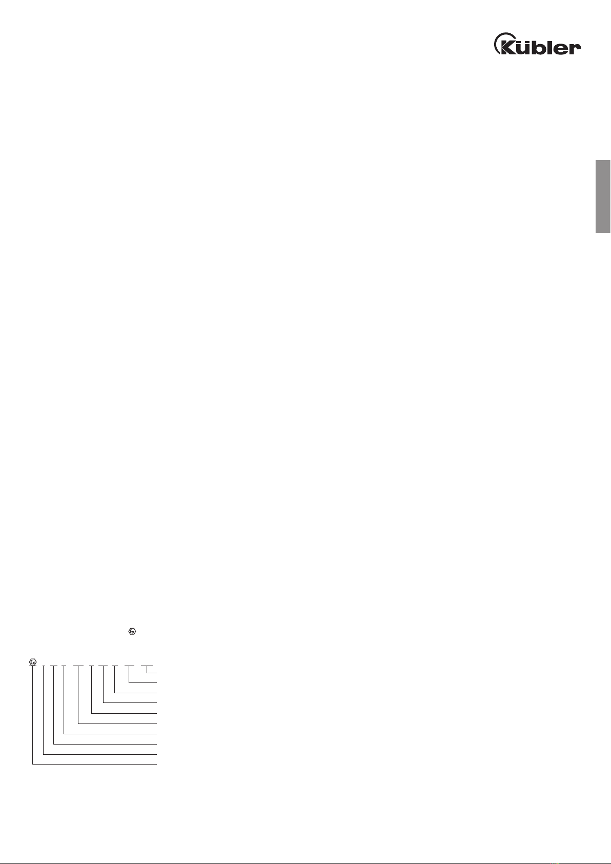
EX Classification
The Kübler Ex encoders comply with the requirements of EC Directive 94/9/EC for potentially explosive atmospheres and of the IECEx Scheme. They
are classified according to I M2 Ex d I/IIC T4-T6 Mb.
EC Type Examination Certificate:
I M 2 Ex d I/II C T4 Mb
Device protection level
Temperature class
Gas group C
Explosion group I and IIC
Flameproof enclosure
Explosion-protected equipment
Extent of the safety to be ensured
Category M
Explosion group I - mines
Explosion-protected equipment with type examination certificate)
T4 = maximum permissible surface temperature 135°C1)
1)max. speed = 6000 RPM and ambient temperature –40°C .... +60°C