Before You Begin (cont.)
flux or acids directly to the valve, as damage to the seals,
plastic components, and trim finish may result.
CAUTION: Risk of product damage. Do not apply
petroleum-based lubricants to the valve components, as
damage may result.
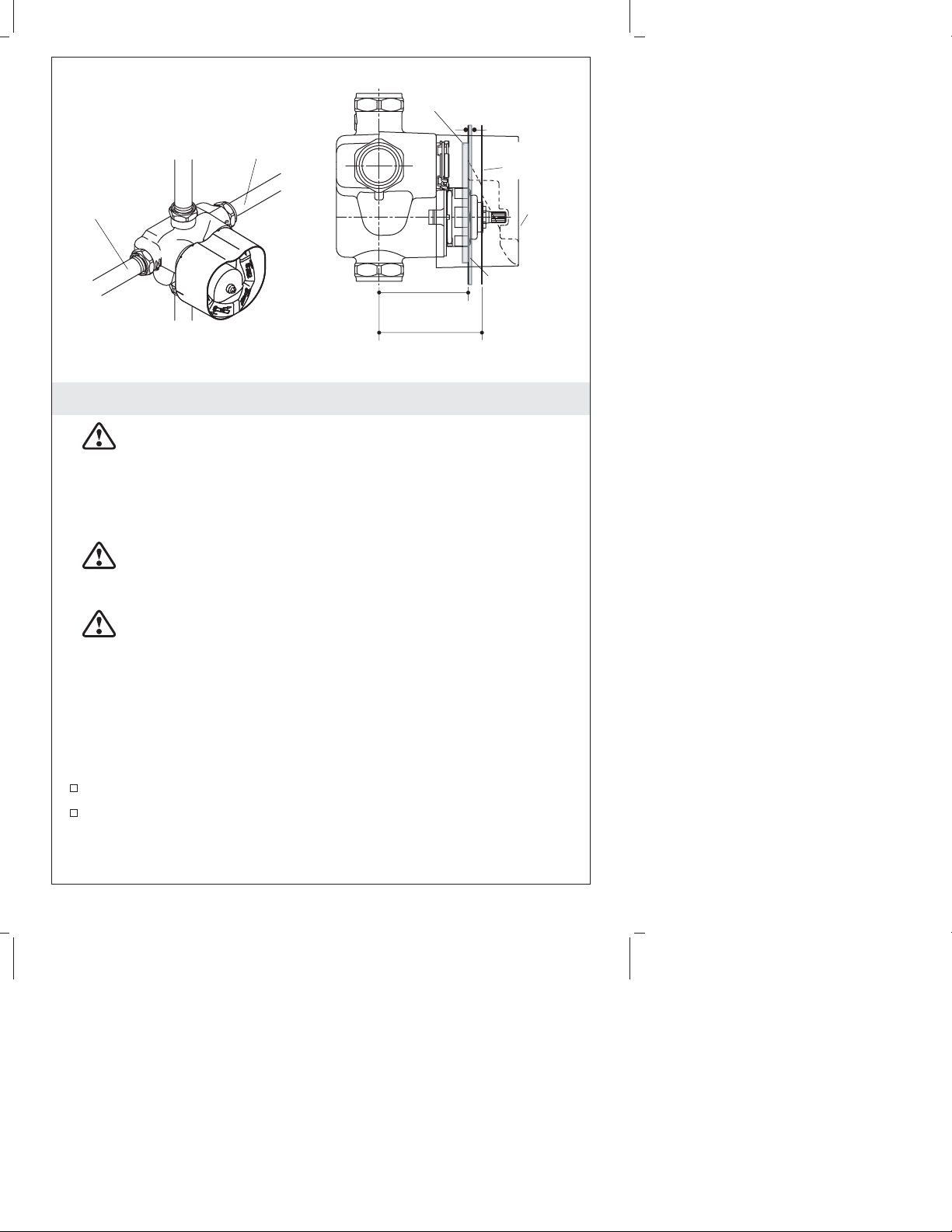
CAUTION: Risk of product damage. Inlet and outlet
threaded joint connections should be made with plumbers
PTFE tape or liquid sealant. Oil-based, non-setting
compounds should not be used.
CAUTION: Risk of personal injury. The water temperature
should never be set above 120°F (49°C).
Observe all local plumbing and building codes.
Shut off the main water supply.
Inspect the supply piping for damage. Replace as necessary.
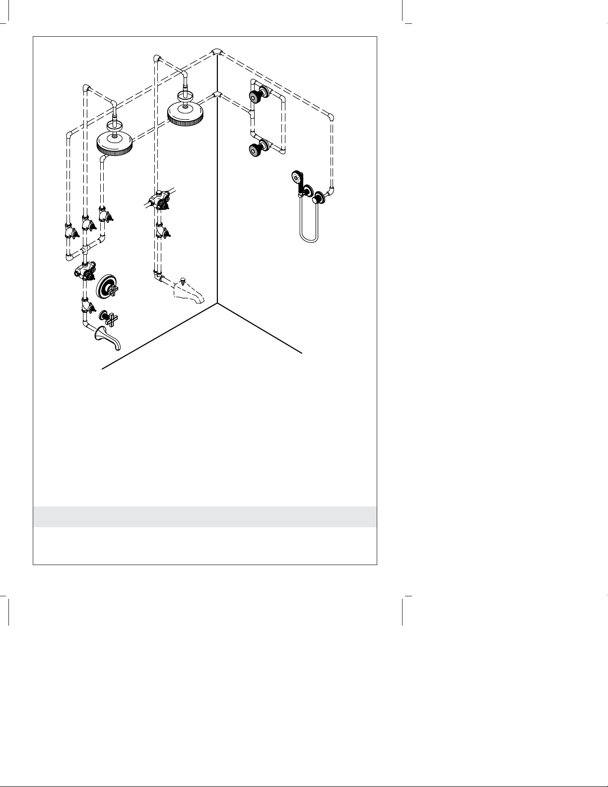
The bottom port of the thermostatic mixing valve is intended for
use as a bath filler only. If a bath spout is not used with this
product, cap the bottom port.
The thermostatic mixing valves do not contain an integral volume
control/shut-off valve. You must install a separate volume
control/shut-off valve downstream of any used valve outlet.
The thermostatic mixing valves do not have an integral aspirator.
For installations that use a bath diverter spout, you must install a
twin ell with integral aspirator between the valve and the bath
spout. If these thermostatic mixing valves are installed without an
aspirator, it will cause water to flow from the shower and bath
spout at the same time.
Determine the correct drain size and capacity for your
installation. If two thermostatic mixing valves are used together,
water volumes between 18 and 30 gpm (60 and 114 lpm) or more
are possible, depending upon the water supply pressure.
Determine the correct water heater size and capacity for your
installation. A typical shower installation uses an approximate
mix of 75% hot water and 25% cold. A custom shower application
using three 2-1/2 gpm (9.5 lpm) showerheads can use about 45
gallons (170 liters) of hot water in 8 minutes. Choose a water
heater large enough for your installation.
1048326-2-B 4 Kallista