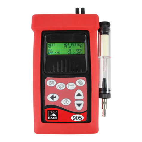
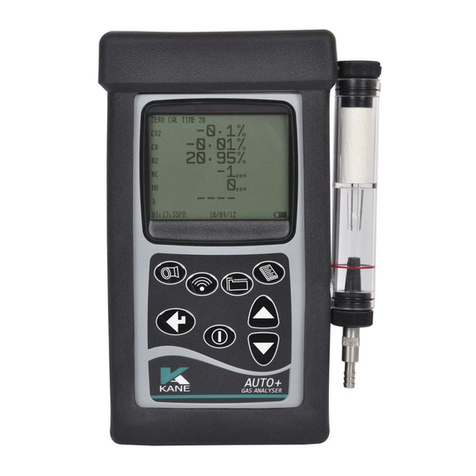
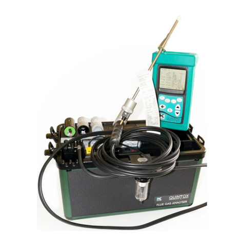
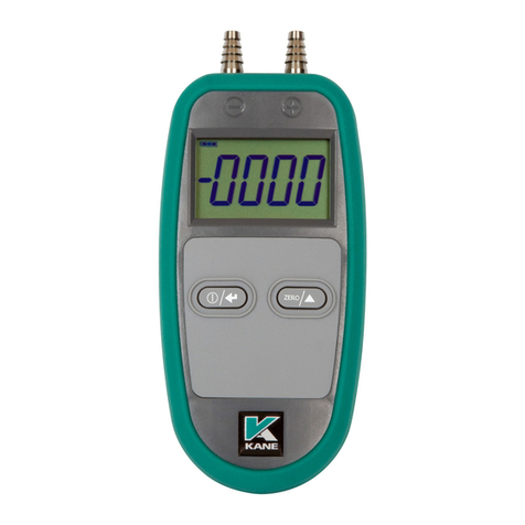
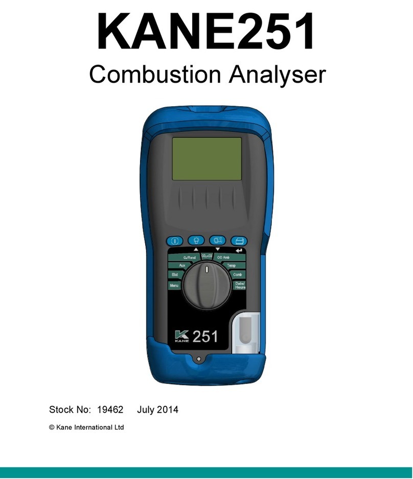
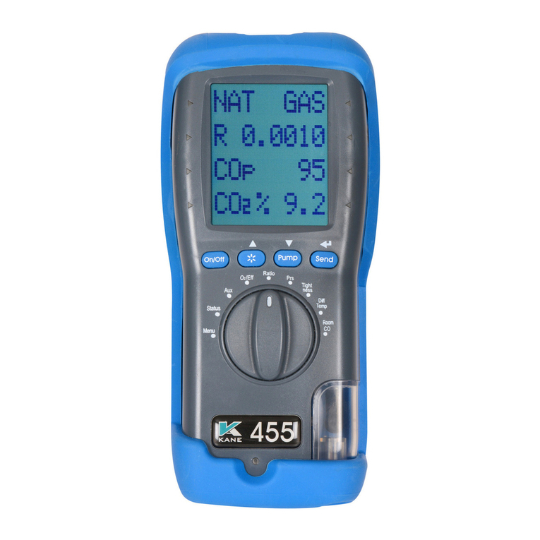
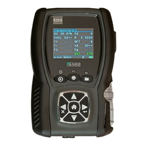
Kane KANE504 Guide

KANE504
Combustion Analyser
Stock No: 19101-2 April 2012
© Kane International Ltd

- 2 -
CONTENTS
Page No:
OWNERS MANUAL & MAINTENANCE 3
1. GETTING STARTED 4
1.1 SAFETY NOTES 4
1.2 PRE-TEST CHECKLIST 4
1.3 STORING INLET TEMPERATURE 4
1.4 SELECTING FUEL 5
1.5 ANALYSER CONNECTIONS 5
1.6 POST TEST 6
2. MAINTENANCE 6
2.1 GENERAL MAINTENANCE 6
2.2 PERIODIC SERVICE 6
2.3 ANNUAL RE-CALIBRATION 6
2.4 CLEANING 7
2.5 EMPTYING AND CLEANING THE IN-LINE WATER TRAP 7
2.6 CHANGING THE PARTICLE FILTER 7
2.7 BATTERIES REPLACEMENT 8
3. METER PROBLEM SOLVING 9
4. METER SPECIFICATION 10
5. ELECTROMAGNETIC COMPATIBILITY 11
6. GLOSSARY 12
6.1 SELECTOR AND DISPLAY PARAMETERS 12
6.2 FUELS AVAILABLE 13
7. CLEANING 13
8. ANNUAL RECALIBRATION AND SERVICE 13
8.1 RETURNING YOUR ANALYSER TO KANE 14

- 3 -
OWNERS MANUAL & MAINTENANCE
The KANE504 Flue Gas Analyser tests heating appliances for carbon
dioxide (CO
2
), carbon monoxide (CO), Flue Temperature and
Combustion Efficiency.
It is suitable for use with all common ‘domestic’ fuels including Natural
Gas, Propane, Heavy Oil, LPG and Light Oil. (When used with oil
burning appliances the flue gases should only be sampled after the
smoke level has been measured and has been confirmed to be a very
low smoke number.)
It uses a bespoke Non-Dispersive InfraRed (NDIR) sensor to directly
measure CO
2
and a long life electrochemical sensor to measure CO.
The meter is controlled using a rotary dial.
The dial positions are:
OFF
STANDBY Pump off
CO ppm carbon monoxide
CO
2
% carbon dioxide
O
2
% Oxygen
RATIO CO/CO2
T FLUE Flue temperature
EFF Combustion Efficiency
Note: Ratio is shown to 4 decimal places, but without a decimal point. So
0001 on the display is equivalent to 0.0001

- 4 -
1. GETTING STARTED
1.1 SAFETY NOTES
Before using this meter, read all safety information carefully. In this
manual the word “WARNING” is used to indicate conditions or actions
that may pose physical hazards to the user. The word “CAUTION” is
used to indicate conditions or actions that may damage this instrument.
WARNING!
This analyser extracts combustion gases that may be toxic in relatively
low concentrations. These gases are exhausted from the back of the
instrument. This instrument must only be used in well-ventilated
locations. It must only be used by trained and competent persons after
due considerations of all the potential hazards.
1.2 PRE-TEST CHECKLIST
Clean particle filter
Water trap and probe line are empty of water
Power on and zero
All hose and thermocouple connections are properly secured
Flue gas probe is sampling ambient FRESH air
Water trap is fitted correctly to the instrument
Flue temperature plug is connected
Inlet temperature probe is connected if required
1.3 STORING INLET TEMPERATURE
To correctly calculate net temperature and combustion efficiency it is
important to have the correct inlet temperature set. Two methods are
available to properly establish the inlet temperature.
Non-ducted Systems. If the KANE504 is being used on a system that
uses combustion air from the space near the appliance, simply turn the
analyser on without the flue probe connected. The KANE504 will use an
ambient sensor inside the handset as the inlet temperature to determine
net temperature.

- 5 -
Ducted Systems. If the KANE504 is being used on a system that brings
in outside air for combustion air it is important to set up the inlet
temperature prior to taking flue gas readings. To properly set inlet
perform the following steps during start-up of the KANE504:
Connect the flue temperature connector only to the KANE504.
Place the flue probe in the combustion air inlet system
Turn on and allow to complete the zero process.
Connect the flue gas connector and proceed to combustion
measurements.
The temperature measured during the zero countdown has now been
stored, and will be used to determine the net temperature.
1.4 SELECTING FUEL
When powering on, simply rotate the selector to the desired fuel. The
display will show this, and then it will complete the zero process.
NOTE: If you wish to use the same fuel as previously selected rotate the
selector to “Stand By” at power on. The fuel in use will be displayed and
then blink. If the fuel is not correct rotate the selector to the proper choice
before the zero countdown starts.
1.5 ANALYSER CONNECTIONS
NOTE: Take care when inserting the temperature probes as the pins are
polarized. Insert with the smaller pin into input marked positive. (+)
CAUTION!
Turning the pump off while the probe is in the flue will leave toxic gases
inside the analyser. Once data has been read, it is advisable to purge the
unit with fresh air as soon as possible. To do this, with the probe
removed from the flue, turn ON the pump. Always allow the readings to
return to zero (0.0 for CO2) prior to shutting the unit off.
CAUTION!
The probe will be hot from flue gases. Remove the probe from the flue
and allow it to cool naturally. Do not immerse the probe in water, as this
will be drawn into the analyser and damage the pump and sensors. Once
the probe is removed from the flue and the readings have returned to
ambient levels rotate the selector to “OFF” and switch off the analyser.
The instrument will count down from 10 to switch off.

- 6 -
1.6 POST TEST
Remove the probe from the flue and allow the analyser to purge with
fresh air until the CO and the CO2 readings return to zero. (Be careful as
the probe tip will be HOT)
Drain water trap.
Check particle filter.
2. MAINTENANCE
2.1 GENERAL MAINTENANCE
Check calibration of your instrument annually to ensure it meets original
performance specifications.
Keep your instrument dry. If it gets wet, wipe dry immediately. Liquids
can degrade electronic circuits.
Whenever practical, keep the instrument away from dust and dirt that
can cause premature wear.
Although your instrument is built to withstand the rigours of daily use, it
can be damaged by severe impacts. Use reasonable caution when using
and storing the meter.
2.2 PERIODIC SERVICE
CAUTION!
Repair and service of this instrument is to be performed by qualified
personnel only. Improper repair or service could result in physical
degradation of the instrument. This could alter the protection from
personal injury this meter provides to the operator. Perform only those
maintenance tasks that you are qualified to do.
2.3 ANNUAL RE-CALIBRATION
While the sensor has an expected life of more than five years in normal
use it is recommended that the analyser is re-calibrated at least annually,
this is so that long-term drift on the electronics can be eliminated. Local
regulations may require more frequent re-calibration and users should
check with appropriate authorities to ensure they comply with relevant
guidelines.

- 7 -
2.4 CLEANING
Periodically clean your instrument case using a damp cloth. DO NOT use
abrasive, flammable liquids, cleaning solvents, or strong detergents as
they may damage the finish, impair safety, or affect the reliability of the
structural components.
2.5 EMPTYING AND CLEANING THE IN-LINE WATER TRAP
The integral water trap should be checked and emptied on a regular
basis. Water vapour will condense in the probe line, which may cause
the water trap to fill suddenly if the probe is moved. Care should be taken
at all times.
Carefully unscrew the plug from the
bottom of the water trap housing.
Dispose of the condensate in a suitable
drain, care must be taken as it could be
acidic. If condensate spills onto the skin
or clothing, clean off immediately using
fresh water, seek medical advice of
problems occur. Ensure plug is
replaced before performing combustion
tests.
NOTE: CO2 reading will be low if the Water Trap Plug is not in place.
2.6 CHANGING THE PARTICLE FILTER
This is a very important part of the analyser and should be changed
regularly. It prevents dust and dirt particles from entering pump and
sensors that will cause damage. The filter MUST be changed when it
appears discoloured.
Remove water-trap assembly from the
analyser as shown above. Remove the
filter and plastic holder from the
housing. Discard the filter element but
keep the holder to fit to the new filter.
Clean the inside of the filter housing
with a suitable soft cloth. Fit the holder
onto the new filter element and then
insert into the housing. Refit the
housing onto the analyser.

- 8 -
2.7 BATTERIES REPLACEMENT
This meter has been designed for use
with alkaline batteries. No other types
are recommended. The analyser is
supplied with 4 “AA” size alkaline
batteries.
These should be installed into the
instrument as shown in the diagram to
the right and indicated on the back of
the unit.
CAUTION!
Take great care when installing the batteries to observe the correct
polarity. Always check the meter for operation immediately after installing
new batteries.

- 9 -
3. METER PROBLEM SOLVING
If any problems are not solved with these solutions, contact us or an
authorised repair centre.
Fault Symptom Causes / Solutions
CO
2
too low Air leaking into probe, tubing, water trap
or connectors.
Meter does not respond to flue
gas
Particle filter blocked.
Probe or tubing blocked.
Pump not working or damaged with
contaminants.
Net temperature or Efficiency
calculation incorrect
Ambient temperature set wrong during
Automatic Calibration.
Flue temperature readings
erratic
Temperature plug reversed in socket.
Faulty connection or break in cable or
plug.
T flue or T net displays (----) Probe not connected or faulty.
EFF display (----) CO
2
reading is too low. No temperature
measurement available
CO reading too low
Air leaking into probe, tubing, water
trap or connectors.
Sensor may be depleted: check against
a known concentration

- 10 -
4. METER SPECIFICATION
(NOTE MAY BE SUBJECT TO CHANGE)
Parameter
Resolution
Accuracy
Range
Flue Temperature
Carbon Dioxide
*1
Oxygen
*2
Carbon Monoxide
*1
Efficiency
*3
0.1 °C
0.1%
0.1%
1 ppm
0.1%
± 2°C + 0.3% Reading
+0.2%
+0.2%
+/- 5ppm <100 ppm
+/-5% of reading >100
ppm
n/a
0-600°C
0 - 21%
0 - 21%
0 to 1999 ppm
0-110%
Dimensions
(approximate)
Weight
Handset
Probe
0.5 Kg
180mm x 85mm x 50mm
250mm x 6mm stainless steel shaft
nominal 0.9m neoprene hose.
Ambient Operating
Range
+0
o
C to 45°C
10% to 90% RH non- condensing
850 to 1100 mbar atmospheric pressure
Battery Life
4 AA cells
>8 hours using Alkaline AA cells
*1
Using dry gases at STP
*2
Calculated assuming Fuel Lean Combustion for.
*3
Calculated

- 11 -
5. ELECTROMAGNETIC COMPATIBILITY
European Council Directive 89/336/EEC requires electronic equipment
not to generate electromagnetic disturbances exceeding defined levels
and have adequate immunity levels for normal operation. Specific
standards applicable to this meter are stated below.
As there are electrical products in use pre-dating this Directive, they may
emit excess electromagnetic radiation levels and, occasionally, it may be
appropriate to check the meter before use by:
Use the normal start up sequence in the location where the meter will be
used.
Switch on all localized electrical equipment capable of causing
interference.
Check all readings are as expected. A level of disturbance is acceptable.
If not acceptable, adjust the meter’s position to minimize interference or
switch off, if possible, the offending equipment during your test.
At the time of writing this manual (Dec 2008) we are not aware of any
field based situation where such interference has occurred and this
advice is only given to satisfy the requirements of the Directive.
This product has been tested for
compliance with the following generic
standards:
EN 61000-6-3 : 2001
EN 61000-6-1 : 2001
and is certified to be compliant
Specification EC/EMC/KI/K500S
details the specific test configuration,
performance and conditions of use.
Please Note: Batteries used in this meter should be disposed of in
accordance with current legislation and local guidelines.

- 12 -
6. GLOSSARY
6.1 SELECTOR AND DISPLAY PARAMETERS ON KANE504:
“2Er0” Analyser is performing the initial zero
setting.
CO2 (Carbon Dioxide) Direct reading of the Carbon Dioxide
Sensor displayed in percentage (%).
CO Carbon monoxide reading in parts per
million.
Eff (Efficiency) Calculated combustion (not appliance)
efficiency based on measurements of CO2,
Flue Temperature and fuel selected. The
KANE504 calculates nett combustion
efficiency and automatically determines if
the combustion is in the condensing mode
to make appropriate corrections.
Ratio The ratio of CO to CO
2
O2 (Oxygen) O2 is calculated for each fuel type from the
CO2 measurement. It assumes that the
combustion process is running fuel lean. It
is important to make other measurements
to confirm that this assumption is always
correct.
TFlue (Flue Temperature) TFlue is a direct measurement of the
temperature at the tip of the flue probe.
This measurement is used to determine the
net temperature for use in calculation of the
combustion efficiency.
BAT symbol Displays the Battery Power available.

- 13 -
6.2 FUELS AVAILABLE
Selector Position Display Type
L Oil LOIL Light Oil
Propane PrOP Propane
Nat Gas nGAS Natural Gas
H Oil HOIL Heavy Oil
Wood wOOd Wood
Coal COAL Coal
7. CLEANING
This product can be cleaned using a damp lint free cloth and a small
amount of non-abrasive detergent. Take care to avoid moisture entering
the sensor’s grill and after cleaning leave the product in a warm dry place
to allow any surface dampness to evaporate. Under no circumstance
should any solvent cleaner be used as this may cause damage to the
plastic case, display and sensor.
8. ANNUAL RECALIBRATION AND SERVICE
Although sensor life is typically more than five years, the monitor should
be re-calibrated and serviced annually to stop any long-term sensor or
electronics drift or accidental damage.
Local regulations may require more frequent re-calibration.
In the UK Kane International has service facilities at Atherton near
Manchester (Tel: 01942-873434), the primary service centre for UK
customers and at Welwyn Garden City in Hertfordshire (Tel: 01707-
375550), the primary service centre for non-UK customers.
By sending your monitor back to Kane for an annual fixed price service
(check www.kane.co.uk for details) you have the opportunity to extend
the warranty on your analyser to 5 years.

- 14 -
8.1 RETURNING YOUR ANALYSER TO KANE
When returning your KANE504, please always ensure that you enclose:
9Your full contact details
9A daytime telephone number
9Details of faults you might have experienced
9Any relevant accessories (eg. probe, printer, adaptor and leak
detectors). Any accessories that are returned will be checked. If an
accessory has failed then we will quote you for a repair or a
replacement.
Packing your analyser
When returning your analyser, please pack it appropriately to prevent
any damage during transit.
Before sealing your package, please ensure that you have enclosed the
items listed above and that it is clearly marked for the attention of:
Northern Service Centre
Kane International Ltd
Gibfield Park Avenue
Atherton
Manchester
M46 0SY
Sending your analyser
Once the analyser has been securely packed then your package is ready
for shipment back to Kane. If you do not have an account with a courier
company you can take your package to your local Post Office. It is
advisable to send the package by Special Delivery so that it is insured
and traceable while in transit.
When we receive your analyser
On receipt of your package, our Service Engineers will inspect the
analyser and any accessories and confirm to you the total service cost.
Once you have accepted this the work will be carried out, and upon
completion the analyser returned to you by Fed Ex “Next Day Service”.
If you have any questions that we haven’t answered, please feel free to
contact our Northern Service Centre:
Tel: 01942 873434
Fax: 01942 873558

- 15 -
Service Returns (Simply cut out and attach to your package)
Northern Service Department
Kane International Ltd
Gibfield Park Avenue
Atherton
Manchester
M46 0SY
Northern Service Department
Kane International Ltd
Gibfield Park Avenue
Atherton
Manchester
M46 0SY
Northern Service Department
Kane International Ltd
Gibfield Park Avenue
Atherton
Manchester
M46 0SY

- 16 -

- 17 -
Product Registration
Please complete, detach and return to: Kane International Ltd, Kane House,
Swallowfield, Welwyn Garden City, Hertfordshire, AL7 1JG
Your Details
Name:
Job Title:
Company Name:
Company Address 1:
Address 2:
Town/City:
County:
Postcode:
Country:
Phone Number:
Fax Number:
Mobile Number:
Email Address:
Product Details
Note: Proof of Purchase may be required for warranty claims.
Date Purchased as numbers
(05.01.10):
Purchased From:
Model Number:
Product Serial Number:

- 18 -
Why did you buy a Kane Product?
Dealer Recommendation Made in the UK
Value for Money Our Fixed Price Servicing Programme
Kane Previous Owner
Not your Decision Other reason:
What brand was your previous analyser?
1
st
time purchase Kane
Testo Telegan
Anton TPI
Other manufacturer:
How did you hear about Kane?
Magazine Advert Trade Counter Literature
Personal Recommendation Internet
Exhibition Other:
Which do you read most often?
Often Sometimes Hardly Ever
Registered Gas Engineer
Gas Installer
P.H.P.I.
P.H.A.M. News
Heating Ventilating & Plumbing
Heating & Plumbing Monthly
Thank you for completing this survey.
All the information we have collected is confidential.
We do not sell or share data with any other company or organisation.

- 19 -

- 20 -
Thank you for buying this
Analyser.
Before use, please register
on our website
www.kane.co.uk
or complete, detach and
return the Product
Registration page.
Table of contents
Other Kane Measuring Instrument manuals
Popular Measuring Instrument manuals by other brands

BGS technic
BGS technic 1943 instruction manual

Accent
Accent ACS Series user manual

C-LOGIC
C-LOGIC 95 instruction manual

Galvanic Applied Sciences
Galvanic Applied Sciences AccuLase-GPA Series Operation & maintenance manual

Endress+Hauser
Endress+Hauser Micropilot M FMR231 operating instructions

PRECISION DIGITAL
PRECISION DIGITAL DART PD602 user guide

Fluke
Fluke Micro-Bath 7102 user guide

humotion
humotion SmarTracks Diagnostics v.3.16 Installation guide & user manual

Wohler
Wohler LM25 Analog Series manual

Alber
Alber UXTM installation guide

Xylem
Xylem ebro TFH 610 manual

PCB Piezotronics
PCB Piezotronics IMI Sensors EX600B14 Installation and operating manual