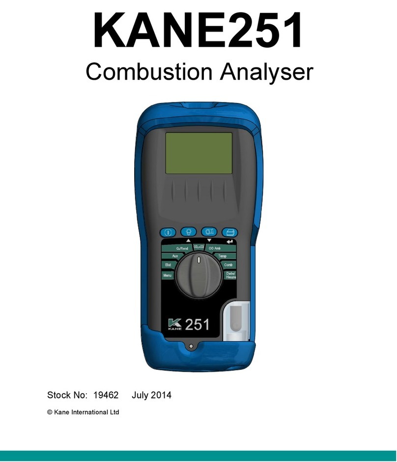
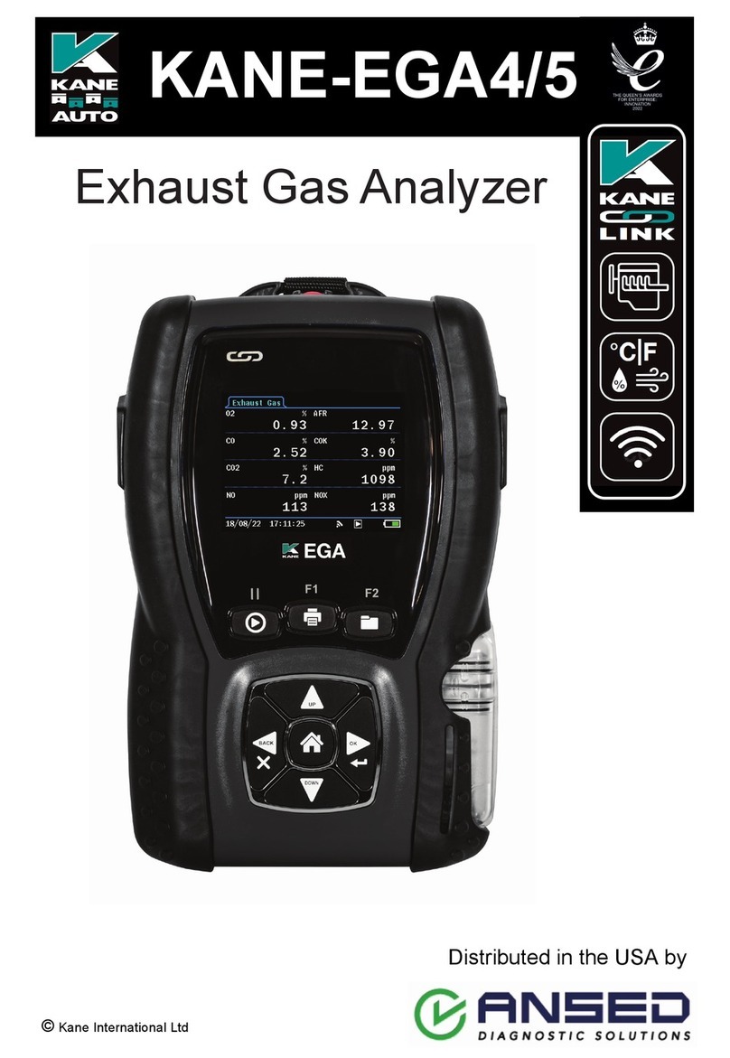
Kane KANE101 User manual

KANE101
Indoor Air Quality Analyser
Stock No: 20103 October 2018
© Kane International Ltd

Page 2
CONTENTS
Page
KANE101 OVERVIEW 4-5
1. ANALYSER LAYOUT & FEATURES 6
2. BATTERIES 7-8
3. BEFORE USING THE ANALYSER FOR THE FIRST TIME 8
4. BEFORE USING THE ANALYSER EVERY TIME 8
5. USING THE ANALYSER AND ITS FOUR BUTTONS 10-11
6. USING THE ROTARY DIAL (starting from Menu) 12-23
6.1 MENU 12-15
6.2 STATUS 16
6.3 AUX 16
6.4 AMBIENT CO2 & CO 17
6.5 IAQ 17
6.6 TIMED LOG 18
6.7 ROOM TEST 19-23
7. MEASURING GASES 24
8. EXAMPLE PRINTOUT IN AMBIENT AIR 25
9. WHEN YOU FINISH USING THE ANALYSER 26
10. MAINTENANCE 27-28
10.1 EMPTYING & CLEANING THE INTEGRAL WATER TRAP 27
10.2 CHANGING THE PARTICLE FILTER 28
11. PROBLEM SOLVING 29
12. KANE DASHBOARD 30-31
13. ONLINE BOOKING PROCEDURE 32-34

Page 3
14. ANALYSER ANNUAL SERVICE & RECERTIFY 35-38
14.1 SERVICE-CALIBRATE-RECERTIFY 35-36
14.2 RETURNING YOUR ANALYSER TO KANE 37
14.3 WHERE TO SEND YOUR ANALYSER 38
15. COLD WEATHER PRECAUTIONS 38
16. SPECIFICATION 39
17. ELECTROMAGNETIC COMPATIBILITY 40
APPENDIX 41
PRODUCT REGISTRATION 43-44

Page 4
KANE101 OVERVIEW
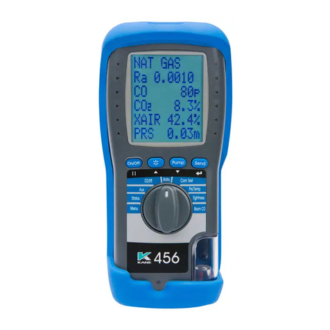
The KANE101 tests for ambient CO and ambient CO2concentrations.
Optionally it will also measure ozone and with an external wand
temperature, humidity and airflow
The large display shows 6 lines of data which can be printed via an
optional infrared printer. The printed data can be 'live' data or 'stored
data'. Data can also be transferred wireless to an Android Printer App or
KANE LIVE software.
The KANE101 is controlled using 4 buttons and a rotary dial.
The four buttons (from left to right)
switch the instrument on and off, or temporarily hold or ‘freeze’
the current reading.
print actual or saved data, switch the backlight on and off,
switch the pump on and off
save data
= Scroll up
= Scroll
down
= Enter
The buttons with , and also change settings such as date, time,
when in menu mode.
The KANE101 can store up to 142 store locations –40 AUX, 40 Ambient
CO2/CO, 40 IAQ, 2 Timed Logs up to 240 tests and 20 Room test.
The KANE101 is powered by internal re-chargeable NiMH batteries. The
internal battery will power the analyser for about 6Hr, from full charge.
The KANE101 has a protective rubber sleeve with a magnet for “hands–
free” operation.

Page 5
NOTE: Fresh air is referred to in this manual. Sometimes it may be
convenient to use thin flexible tubing (min ID. 3mm.) to supply
fresh outside air, if a tube is used ensure that the inlet is at least
1 meter away from any possible source of CO2such as an open
window.
Fuel combustion of any sort may cause high and fluctuating
levels of CO2over surprisingly large areas. Exhaled breath can
easily reach 20,000ppm.
The air in a sealed room is not really fresh so it is really
important to use outside fresh air away from flues, car
exhausts etc

Page 6
1. ANALYSER LAYOUT & FEATURES
INSTRUMENT FEATURES AND KEYPAD
Infra-red Printer emitter
Display
Function Keys
Rotary Switch
Water Trap
& Particle Filter
External Anemometer Connection Gas Inlet
Charging Socket
ON / OFF
Turns analyser ON and
OFF
Scroll key when using the
Menu
PUMP
Turns pump ON and OFF
Scroll key when using the
Menu
PRINT / BACKLIGHT
Print ‘live’ or stored data
Turns on Backlight
Enter key when using the
Menu
STORE
Stores readings in the
Memory

Page 7
2. BATTERIES
Battery Type
This analyser has been designed for use with disposable alkaline
batteries or rechargeable Nickel Metal Hydride (NiMH) batteries. No
other battery types are recommended.
WARNING
The battery charger unit must only be used when NiMH batteries
are fitted. Do not mix NiMH cells of different capacities or from
different manufacturers. All four cells must be identical
Replacing Batteries
Turn over the analyser, remove its protective rubber cover and fit 4 “AA”
batteries in the battery compartment. Take great care to ensure they
are fitted with the correct battery polarity. Replace the battery cover
and protective rubber cover.
Switch the analyser on and check that the analyser’s time and date are
correct. To reset see USING THE MENU, Section 5.
Charging NiMH Batteries
Ensure that you use the correct charger. The part number is 19278.
To fully charge NiMH batteries:
The charger must be connected and switched on.
When charging, the red Battery Charging Indicator will illuminate.
After a few seconds, the display will show “ CHARGING
BATTERY” if they need extra charge.
The first charge should be for 12 hours continuously. NiMH batteries are
suitable for top up charging at any time, even for short periods.
An in-vehicle charger can be used to top up the analyser's batteries from
a 12 volt vehicle battery. The part number is 18342.

Page 8
Battery Disposal
Always dispose of depleted batteries using approved disposal methods
that protect the environment
3. BEFORE USING THE ANALYSER FOR THE FIRST
TIME:
Set the correct time, date etc, after it is switched on and calibrated –See
USING THE ROTARY DIAL below. These are stored when the analyser
is switched off.
4. BEFORE USING THE ANALYSER EVERY TIME:
Check the water trap is empty and the particle filter is not dirty:
- To empty the water trap, unscrew its red stopper and re-screw
once it is empty.
- To change the filter, remove protective rubber sleeve, pull out the
water trap , remove the water trap’s particle filter from the spigot
and replace. Reconnect the water trap and rubber protective
sleeve.
Remember to always switch on in outside fresh air.
After switch on check that date and time are correct and battery power is
sufficient.
Avoid exposing the instrument to sudden large temperature changes,
and ensure that the unit reads zero for CO and approx. 400 ppm CO2in
fresh outside air before use. If necessary re-zero.

Page 9
SAFETY WARNING
This analyser can be used to extract combustion gases that may be toxic
in relatively low concentrations. These gases are exhausted from the
back of the instrument. This analyser must only be used in well-
ventilated locations by trained and competent persons after due
consideration of all the potential hazards.
It is recommended that the analyser is switched on in outside fresh
air so that the levels of CO when entering a premise can be
measured and any potential danger can be spotted.
Users of portable gas detectors are recommended to conduct a “bump”
check before relying on the unit to verify an atmosphere is free from
hazard.
A “bump” test is a means of verifying that an instrument is working within
acceptable limits by briefly exposing to a known gas mixture formulated
to change the output of all the sensors present. (This is different from a
calibration where the instrument is also exposed to a known gas mixture
but is allowed to settle to a steady figure and the reading adjusted to the
stated gas concentration of the test gas).

Page 10
5. USING THE ANALYSER AND ITS FOUR BUTTONS:
Switching
ON the
analyser
Or HOLD
the
readings
Press the button to switch the unit ON outside in
fresh air. This allows the analyser’s sensors to be
calibrated. This will set CO to zero and CO2to around 400
ppm .
At switch on, the analyser beeps four times and displays
the model number. The bottom line counts down from
typically 90 seconds.
When the analyser is running in measurement mode a
quick press of this key will HOLD the reading. Another
quick press will release the readings.
Switching
OFF the
analyser
Press the button to switch the analyser OFF. The
display counts down from 30 with the pump on to allow time
for the sensors to be cleaned or purged with fresh air. If the
probe is connected, make sure both analyser and probe are
in fresh air.
Press / if you want to stop the count-down to off
and return to making measurements.
Using
/ /
Buttons
Once the “on” countdown has been completed:
Use the / / keys to change settings (such as
time and date ) when the rotary dial is turned to MENU.
Use the
key
Press to save readings if memory locations are available.
The display will flash LOG xxx (or FULL) to give the store
location of the saved data.

Page 11
Switching
on and off
the
backlight.
Press for about 2 sec. and release to switch backlight
on or off.
Note: use of the backlight increases the drain on the
battery.
Printing
Data
Press to start the analyser printing. The analyser
displays "PRINTING" until this is completed.
Make sure the printer is switched on, ready to accept data
and its infrared receiver is in line with the emitter on top of
the analyser.
Switching
PUMP on /
off
The analyser normally operates with the pump on. Press
to switch the pump off and on.
When the pump is switched off, the analyser displays
"PUMP OFF" approx every 20 seconds.
“Freezing”
the display
Press to freeze all readings. The display flashes and
can be printed by pressing the PRINT key. Press again for
“live” measurements.

Page 12
6. USING THE ROTARY DIAL (starting from Menu):
Rotor positions are:
•Menu the MENU options are listed below
Status display time, date, time ambient temp, days
before CAL due, battery level .
•Aux 6 lines of user defined parameters
Amb CO + CO2 displays CO and CO2reading in ppm with
average and …. max.
•IAQ 6 measured values
•Timed Log user selected logging periods 1 to 24 hours
•Room Test structured Room testing
6.1 MENU SELECTION .
MENU
Rotate the dial to MENU and use the , and buttons
as described fully below to select and change the following
functions:
1.SETUP
2. ALARMS
3. SCREEN
4. REPORT
5. SERVICE
Using , and keys.
When you have selected the function to change, press to
select.
Repeat this to scroll through the menu and select (using the
key) and change (using the / keys) the function.

Page 13
The final, logical returns you to the main display.
To exit the Menu function at any time, rotate the dial to another
position - Unless the final logical is pressed, no changes are
made.
SETUP
Language
Select language
Set Time
Set current time
Set Date
Set date format and current date.
Printer
Choose KM IRP, KANE IRP-2, SERIAL or WIRELESS
Passkey
Default is 1 1 1 1
Pump flow
Set flow rate 1 to 4.
Gas
ppm or mg/m3
Temp
C or F
Readings
Clear all readings from memory
Back
ALARMS
CO set
Turn alarm on or off
CO level
Set alarm level in ppm
CO2 set
Turn alarm on or off
CO2 level
Set alarm level in ppm
BACK

Page 14
SCREEN
Contrast
Adjust screen contrast. Default = 14
Backlight
Adjust backlight switch off time 0 to 300 secs
AUX
Choose which parameter to display on the 6 lines of the
screen
Back
REPORT
AUX
View or delete
AMBIENT
View or delete
IAQ
View or delete
TIMED LOG
View or delete
ROOM TEST
View or delete
HEADER
Set Line 1 and Line 2 or the printed header
BACK
SERVICE
Reserved for approved service agents.

Page 15
REPORT Functions
With the rotor pointing to MENU use the /keys to select REPORT
and press
The /keys can then be use to select which report you want to
view.
Press ENTER to make a selection.
Use ENTER to toggle the change mode. With the side pointer flashing
you can use UP/DOWN to change that line’s display.
When the side pointers are not flashing the UP/DOWN keys change the
line to be worked on.
VIEW
The top line displays the LOG No
Use /to select next view number (within the range of
data stored up to 142 maximum –40 AUX, 40 Ambient
CO2/CO, 40 IAQ, 2 Timed Logs and 20 Room Test)
The second line displays the LOG time and DATE.
With the side pointer flashing you can toggle between date
and time.
Lines 3 4 and 5 display stored measurement.
With the side pointers flashing on any of these lines you can
scroll through all the measured parameters
The bottom line displays PRINT.
Scroll down to this line to print the stored data

Page 16
6.2 STATUS
STATUS DISPLAY
Select “Status” on the dial to view the following:
14:56:29
→
Current time. Can be re-set via the
“Menu”
11/03/06
→
Current date. Can be re-set via the
“Menu”
Ta
23.8C
→
Ambient temperature of the analyser
CAL
283
→
Shows number of days until next
calibration is due
BAT
→
Shows the charge level of the batteries
6.3 AUX
This is a user defined display.
Typical AUX display
FLOW
0.0m
→
The AUX (auxillary) display can be
customised via MENU / SCREEN / AUX.
R H
35%
→
The parameters displayed on lines 1,
2, 3, 4, 5 and 6 can be set by the user.
CO
52p
→
They remain the AUX parameters until
changed by the user.
CO2
1234p
Ta
22.4C
ExT
35.2C
The displayed parameters are set by the user using a MENU function.
These setting are then retained.

Page 17
6.4 AMB CO2 + CO
CO 0p
→
Current CO reading
CO2 1234p
→
Current CO2 reading
COa
52p
→
Average CO reading
CO2a
945p
→
Average CO2 reading
COm
88p
→
Maximum CO reading
CO2m
3456p
→
Maximum CO2 reading
These instantaneous readings can be held, stored or printed.
6.5 IAQ
CO 35p
→
Measured CO reading
CO2 1234p
→
Measured CO2reading
Ta
25.2C
→
Ambient temp.
ExT
32.2C
→
Wand temperature
RH
88.7%
→
Wand relative humidity %
FLOW
1.1m
→
Wand airflow reading
External temperature, relative humidity and airflow are only available with
the use of the optional wand.
OZONE measurement is only available as an option if specified at the
time of purchase.

Page 18
6.6 TIMED LOG
TIMED LOG
SELECT
LOGGING
PERIOD
HOUR
4
Logging period can be adusted from 1 hour up to 24 hours.
240 measurements are stored.
Only two sets of 240 measurements are retained in memory.
Always ensure that there is enough charge in the batteries to cover the
full test time or plug in the battery charger.

Page 19
6.7 ROOM TEST
Select “Room Test” to measure and record CO and CO2 readings for up
to 30 minutes.
SELECT
ROOM TEST
→
Use / to select the test type
from the following:
TEST TYPE
GENERAL
TEST TYPES
GENERAL:
15 minute test with results
stored every minute
LIMIT = 10ppm
ALARM = 30ppm
USER TYPE:
Parameters are set by the
user
SWEEP TEST:
2 minute test with max
reading stored at end
LIMIT = 10ppm
ALARM = 30ppm
MIGRATION TEST:
15 minute test with results
stored every minute
LIMIT = 10ppm
ALARM = 30ppm
TYPE C SEALED
APPLIANCE:
15 minute test with results
stored every minute
LIMIT = 10ppm
ALARM = 30ppm

Page 20
TYPE B BOILER OPEN
FLUE:
15 minute test with results
stored every minute
LIMIT = 10ppm
ALARM = 30ppm
TYPE A COOKER:
30 minute test with results
stored every minute
LIMIT = 30ppm
ALARM = 90ppm
TYPE A WATER
HEATER:
5 minute test with results
stored every minute
LIMIT = 10ppm
ALARM = 30ppm
TYPE A SPACE
HEATER:
30 minute test with results
stored every 1 minute
LIMIT = 10ppm
ALARM = 30ppm
Typical ROOM TEST display
ROOM
TEST
1/30
→
Test progress (Test 1 of 30)
INT
40s
→
Test countdown
CO2
1234p
→
Measured CO2
CO
0p
→
Measured CO
Limit
10p
→
CO limit for this test
The user can stop the Room test at any time by pressing PRINT
If not stopped earlier, the Room test will automatically end after the
designated time.
The Room test series is automatically stored in the memory as a log
number.
When completed the log can be printed immediately by pressing .
Table of contents
Other Kane Measuring Instrument manuals
Popular Measuring Instrument manuals by other brands

BRP
BRP I-Command Evinrude Etec Series user guide

Gossen MetraWatt
Gossen MetraWatt SECULIFE IM Quick setup guide

SCS
SCS CTC337 Installation, operation and maintenance

Robuschi
Robuschi SENTINEL Operating and maintenance instructions

Wohler
Wohler KM 410 Operation manual

QNAP
QNAP iSignager iS-3620 Quick installation guide