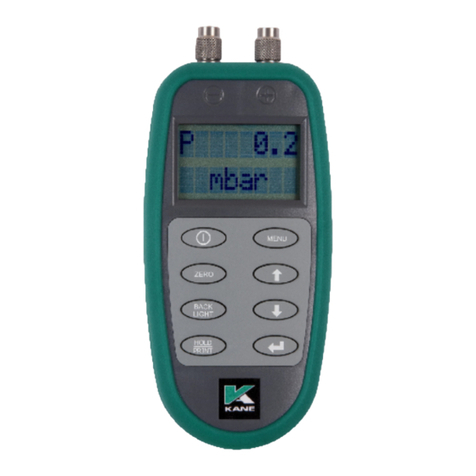
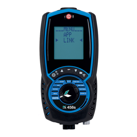
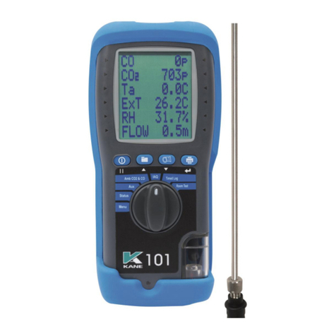
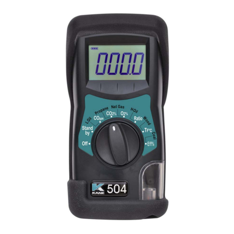
Kane KANE988 User manual

KANE988
Stock No: MAN00333 Rev: 1.00722 JULY 2022
© Kane International Ltd
Industrial Flue Gas Analyser
KANE LINK

CONTENTS Page No.
KANE988 OVERVIEW 4-5
ANALYSER FEATURES AND KEYPAD 6-9
KEYPAD BUTTONS 7
ANALYSER LAYOUT 8
BACK OF ANALYSER & PROBE 9
BATTERIES 10
BATTERY TYPE 10
REPLACING BATTERIES 10
TIME AND DATE 10
CHARGING NIMH BATTERIES 10
BATTERY DISPOSAL 10
GENERAL SAFETY 11
FIRST TIME USE 12
GENERAL OPERATING PRINCIPLE 12
USER INTERFACE 13
LOGGING DATA 13
PRINTING DATA 13
HOME MENU 14
MEASUREMENT 14
SETTINGS 15
REPORTS 16
ON SCREEN TRENDS 17
STATUS 18
SETUP 19
TOOLS 20
USING YOUR ANALYSER 21
2 KANE988 MANUAL

MEASUREMENT MENU 22-28
FLUE GAS 23
PRESSURE & TEMP 24
AIRFLOW 24
DTHA2 SCREEN 24
PITOT SCREEN 24
TIMED LOGGING 25
TEST RUNNING 25
AVERAGE TEST 26
FIND MIDSTREAM 26
STABILISING 26
TEST RUNNING 26
TIGHTNESS TEST 27
CHOOSE LET-BY 27
LET-BY RUNNING 27
START STABILISATION 28
STABILISATION RUNNING 28
START TIGHTNESS TEST 28
TIGHTNESS TEST RUNNING 28
PRESSURE MEASUREMENT GOOD PRACTICE 29
MEASURING FLUE GASES 30
TAKING A PRESSURE READING 31
TAKING A FLOW READING PITOT 31
REGULAR CHECKS DURING SAMPLING 31
NORMAL SHUTDOWN SEQUENCE 32
PRINTOUTS 33-34
WATER TRAP MAINTANENCE 35-36
KANE LINK - ADDING DEVICES 37-38
SPECIFICATIONS 39-40
EU DECLARATION 41
COLD WEATHER PRECAUTIONS 42
WELCOME TO KANE CARE 43-46
ANALYSER RECYCLING 47
KANE988 MANUAL 3

KANE988 OVERVIEW
Your KANE988 combustion analyser uses up to 6 electrochemical
sensors and our proprietary NDIR 3 gas detection bench to measure up
to 8 gases and 9 sensors.
Your KANE988 has a colour graphical display and intuitive keypad to provide
clear information and simple operation.
Your KANE988 is independently certified to EN50379 parts 1-3 by TUV.
Your KANE988 measures (sensor dependent):
• Carbon Monoxide (CO)
• Oxygen (O2)
• Carbon Dioxide (CO2)
• Nitric Oxide (NO)
• Nitrogen Dioxide (NO2)
• Sulphur Dioxide (SO2)
• Hydrogen Sulphide (H2S)
• Hydrocarbons (HC)
• Pressure
• Differential Pressure
• Temperature
• Differential Temperature
Your KANE988 also calculates (sensor dependent):
• Nitrogen Oxides (NOx)
• CO/CO2 ratio
• Combustion Efficiency
• Losses
• Excess Air
• Poison Index (Pi)
• Airflow Pitot tube
Your KANE988 has an integral protective rubber cover and easy fit accessory
clip on rear above the battery compartment.
Your KANE988 flow detector system automatedly protects your analyser if a
blockage is detected in the sampling system.
4 KANE988 MANUAL

Your KANE988 prints test results using an optional infrared printer or
wirelessly sends test results to the KANE LIVE App.
MEMORY
Your KANE988 stores:
• Combustion logs = 178
• Pressure/Temp logs = 178
• Airflow logs = 89
• DTHA2 logs = 89
• Tightness logs = 146
• Average logs = 117
• Timed Logs = 2 * 1440
You can enter 2 lines of 24 characters to personalise your test results.
KANE LINK
You can wirelessly connect optional KANE LINK devices to your analyser.
When connected, they stay connected until you use KANE LINK to remove
them.
When powered on, KANE LINK devices replace or add measurements to
your analyser.
See page 37 to add or remove optional KANE LINK devices.
CO PROTECTION AND AUTO RANGE
Your KANE988 has an electrochemical CO sensor measuring to 10,000ppm
and an NDIR CO sensor measuring to 100,000ppm / 10%.
Above 10,000ppm the NDIR sensor automatically manages CO to
100,000ppm / 10% while the electrochemical CO sensor is protected by the
over range protection pump.
KANE988 MANUAL 5

ANALYSER FEATURES AND KEYPAD
6 KANE988 MANUAL

KEYPAD BUTTONS
ICON DESCRIPTION
PLAY / PAUSE
Pump On / Off
PRINT F1
HOME
Return to home screen
STORES / F2
Short press to Store / F2
UP
Short press to scroll up
DOWN
Short press to scroll down
BACK / CANCEL
BACK / CANCEL
OK / ENTER
OK / ENTER
KANE988 MANUAL 7
Short press to print a report - Analyser
offers destination choice when wireless & irda fitted

ANALYSER LAYOUT
Power On / Off
Function Keys x 3
- see below
Scroll Up
Water trap
8 KANE988 MANUAL
Flue Temperature T1
Store / F2Pump On / Off
Pressure connection P1
OK / Enter
Particle
filter
Analyser Connections
- see section 2
Battery charger
connection
Home
Back / Delete
Scroll Down
Flue gas inlet
Print / F1
Fit spigot probe to
hose before
connecting to
Flue gas inlet
Exhaust port
DO NOT
COVER
Pressure connection P2
Flue Temperature T2

KANE988 MANUAL 9
Thermocouple
Stainless steel
shaft
Depth stop
cone Gas exhaust
ports
Thermocouple
Wire
Depth stop
cone

BATTERIES
BATTERY TYPE
Your analyser uses rechargeable Nickel Metal Hydride (NiMH) batteries.
Using other battery types may void your analyser warranty.
WARNING
Although you can use Alkaline batteries do not charge your analyser
with Alkaline batteries fitted.
Do not mix NiMH cells with different capacities or from different
manufacturers - All batteries must be identical.
REPLACING BATTERIES
Turn over your analyser & remove battery compartment cover.
Fit 6 x NiMH “AA” rechargeable batteries with correct battery polarity.
Replace battery compartment cover.
TIME AND DATE
After changing batteries reset your analyser time & date.
CHARGING NiMH BATTERIES
Your first charge should be for 8 hours - Thereafter NiMH batteries can be
topped up any time, even for short periods.
BATTERY DISPOSAL
Always dispose of depleted batteries using approved disposal methods that
protect the environment.
10 KANE988 MANUAL

GENERAL SAFETY
SAFETY WARNING
Your analyser extracts combustion gases that may be toxic in relativity low
concentrations.
These gases are exhausted from the back and bottom of the analyser.
This analyser must only be used in well-ventilated locations by trained and
competent persons after due consideration of all potential hazards.
Portable gas detectors should conduct “bump” tests before relying on units to
verify atmospheres are free from hazards.
A “bump” test checks an analyser works within acceptable limits by briefly
exposing it to known gas mixtures to change output of sensors present.
NOTE: This is different from a calibration where your analyser is
exposed to known gas mixtures but allowed to settle to a steady figure
with readings adjusted to the test gas concentration.
Protection Against Electric Shock - (In accordance with EN 61010-1:2010).
This analyser is designed as Class III equipment and should only be
connected to SELV (Safety Extra Low Voltage) circuits.
The battery charger is designated as:
• Class II equipment
• Installation category II
• Pollution degree 2
• Indoor use only
• Altitude to 2000m
• Ambient temperature 0°C -40°C
• Maximum relative humidity 80% for temperatures up to 31°C
decreasing linearly to 50%RH at 40°C
• Mains supply fluctuations not to exceed 10% of the nominal voltage
KANE988 MANUAL 11

FIRST TIME USE
Charge your analyser batteries for 8 hours - an overnight charge
should be sufficient for an average 8-hour day.
Take time to read this manual fully and be aware your analyser configuration
may not support all features explained in this manual.
Before use set up your analyser to your requirements.
GENERAL OPERATING PRINCIPLE
After powering on your analyser, choose tasks to perform using MENU.
Most tests can be made with little user activity.
Your analyser status bar displays useful information.
12 KANE988 MANUAL

USER INTERFACE
Navigate via the 5 button control panel - press HOME to return to HOME MENU:
LOGGING DATA
Press STORE key until display shows LOG STORED.
PRINTING DATA
Press PRINT key to select print destination.
Press ENTER key - display changes to show print progress.
To print logged data:
Select LOG ON in REPORTS menu
Press PRINT key or select desired test from MEASUREMENT MENU and
use View Logs
Select LOG NO and press PRINT key
KANE988 MANUAL 13

HOME MENU
NOTE: Your analyser STATUS bar displays current time, date and
battery status.
Check time & date are correct as they can only be changed if you have
no stored logs in Memory to protect integrity of stored data.
MEASUREMENT
Start measurements and tests
See page 22 for details
14 KANE988 MANUAL
Press HOME to display HOME MENU list.
Status bar
MENU ITEM COMMENTS
MEASUREMENT Menu to select task to perform
SETTINGS Change date, time, measurement parameters, alarms etc
REPORTS Configure logging parameters and view stored data
ON-SCREEN TRENDS Configure and display trend information
STATUS Current instrument status, software vertion etc
SETUP Menu to change analyser settings
TOOLS Manual air and pressure zero, mid-stream finder tool
SERVICE Reserved

SETTINGS
Enter changes.
MENU ITEM OPTIONS / COMMENTS
DATE / TIME Set date and time - NOTE: Can only change if all logs in
memory are cleared
FUEL TYPE Select desired option via UP / DOWN and OK to confirm
EFFICIENCY Select desired option via UP / DOWN and OK to confirm
GAS UNIT Select desired units required for measured gas parameter
TEMPERATURE Select desired option via UP / DOWN and OK to confirm
PRESSURE Select desired option via UP / DOWN and OK to confirm
REFERENCE O2 Set reference O2 for CO and NO sensor
independently
ALARMS Toxic Gas Alarm YES / NO
Battery Low Alarm YES / NO
Watertrap Check Warning YES / NO
Excessive CO Warming YES / NO
CONVERSATION FACTORS Select desired Pitot factor
KANE988 MANUAL 15

REPORTS
Create, edit and remove reports
MENU ITEM OPTIONS / COMMENTS
VIEW COMB. REPORTS View reports
VIEW PRS & TEMP REPORTS View reports
VIEW AIRFLOW REPORTS View reports
VIEW DTHA2 REPORTS View reports
DELETE REPORTS Select by report type or all
16 KANE988 MANUAL

ON-SCREEN TRENDS
Create and display custom measurement trends
MENU ITEM OPTIONS / COMMENTS
SETUP Set:
SAMPLING INTERVAL
TREND A Parameter
TREND B Parameter
TREND C Parameter
TREND D Parameter
START TREND A Start
STATY TREND B Start
START TREND C Start
START TREND D Start
START DUAL TREND AB Start
START DUAL TREND CD Start
START QUAD TREND Start
KANE988 MANUAL 17

STATUS
View current configuration and setup
18 KANE988 MANUAL

SETUP
Make further changes
MENU ITEM OPTIONS / COMMENTS
LANGUAGE Select analyser operating language
OPERATING REGION Select fuel table country or region
ASSET NO. Enter equipment asset number
OPERATION DETAIL Enter operator / owner information
PRINTER Select IR printer type
MANAGE LINK DEVICES Add or remove KANE LINK devices
ALARM LEVELS Set alarm trigger levels for each gas sensor -
MAIN PURGE Set:
MAIN PURGE DURATION Time in seconds
MAIN PURGE INTERVAL Time in minutes
AUTO ZERO YES/NO
USER DEFINED FUELS Add custom fuel types
CHANGE SECURITY PIN Set to stop changes without PIN code entry
KANE988 MANUAL 19

TOOLS
For more accurate measurements
SERVICE
Restricted area for authorized personnel only.
MENU ITEMS OPTIONS / COMMENTS
MANUAL AIR ZERO Manually trigger Air Zero purge.
Always purge in fresh outdoor air
MANUAL PRS ZERO Manually trigger zero calibration for pressure sensor -
Disconnect all pressure hoses first
SETUP MIDSTREAM FINDER Setup MIDSTREAM FINDER Tool parameters,
temperature and pressure limits
START MIDSTREAM FINDER Start MIDSTREAM Finder Tool
20 KANE988 MANUAL
This manual suits for next models
1
Table of contents
Other Kane Measuring Instrument manuals
Popular Measuring Instrument manuals by other brands

Hanna Instruments
Hanna Instruments HI 98140 instruction manual

TCS
TCS 700-40 Installation, operation & maintenance manual

Mobiletron
Mobiletron TX011 Installation and operating instructions

immerSUN
immerSUN iLink Installation & user guide

ATD Tools
ATD Tools ATD-5585 owner's manual

Milwaukee
Milwaukee MW801 user manual