i
CONTENTS
SECTION PAGE
INTRODUCTION 1
TECHNICAL REFERENCE
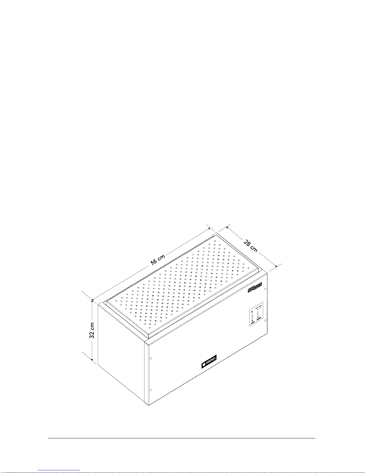
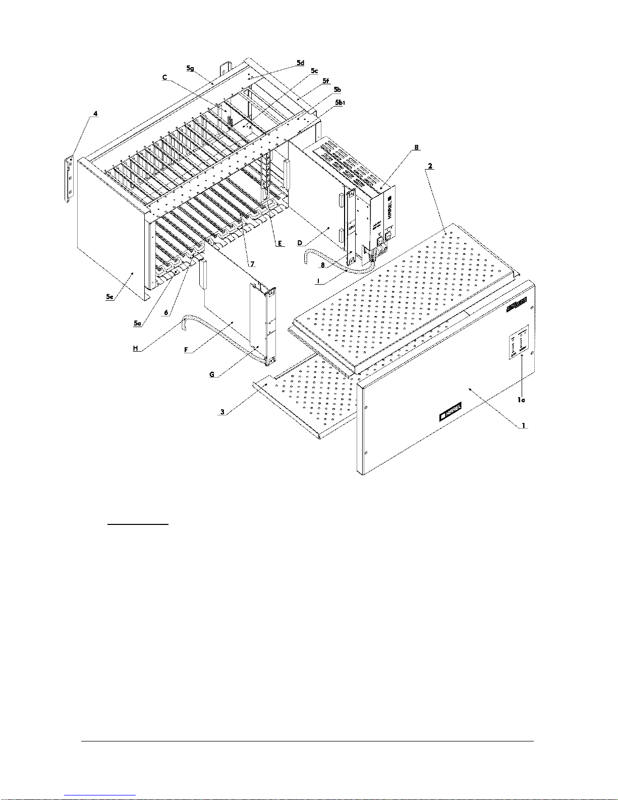
I. SYSTEM 3
I.1. PARTS LIST 4
I.2. BACKPLANE OF THE SYSTEM – BPL224 6
I.3. POWER TO THE SYSTEM 7
I.3.A. POWER SUPPLY MODULE – SPS224 7
I.4. CENTRAL PROCESSING MODULE – CPU224 &
CPU CONNECTION CARD - MS224 CPUKON
9
I.5. EXPANSION MODULES - MS224 EX1 / MS224 EX2 13
I.6. EXTERNAL MUSIC CONNECTOR 19
I.7. EXTERNAL RELAY 19
II. ACCESSORIES 21
II.1. CONSOLES, FEATURE PHONES, DIRECT STATION SELECT
MODULES - OP48(-H), LT48(-H), DSS80, DSS40
22
II.1.A. OP48(-H) CONSOLE 22
II.1.B. LT48(-H) FEATURE PHONE 23
II.1.C. DSS80 DIRECT STATION SELECT MODULE 24
II.1.D. DSS40 DIRECT STATION SELECT MODULE 25
II.2. SERIAL INTERFACE – CM224, PK224, CM224+PK224, SERIAL
PRINTER INTERFACE
26
II.2.A. CM224 CALL RECORD LISTING INTERFACE AND/OR
PK224 PC-CONSOLE INTERFACE 26
II.2.B. SERIAL PRINTER INTERFACE 29
II.3. DOORPHONE – DY01 30
II.4. EXTERNAL ANNOUNCEMENT SYSTEM 31
II.5. AUTO ATTENDANT & VOICE MAIL – EVM224 31
II.6. ISDN ADAPTOR – IA12, EXP-IA12 32
II.7. LOCAL PAGER – PG100 35
II.8. STANDARD TELEPHONE SETS 36
II.9. FILTER & PROTECTION UNIT – FPBASE, FPEXP 37
III. SOFTWARE 39
IV. TECHNICAL SPECIFICATIONS 41