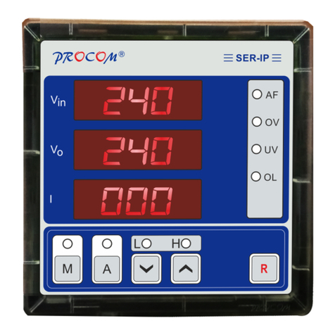
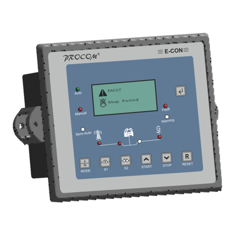
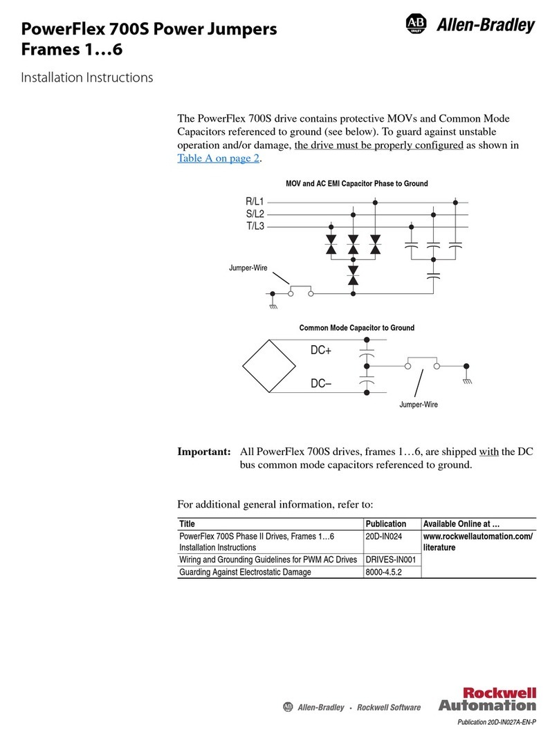
Procom DGC-202 Series User manual

PR C MO O ®
Installation Guide
Rev.-01
OPERATING INSTRUCTIONS
DGC-202X

INDEX
1.0. Introduction
2.0. Model selection
3.0. Specifications
4.0. Salient features, Measurement, Protection & Supervision
5.0. Digital Inputs Outputs
6.0. Modes of Operation
7.0. Analog Sensors in Details
8.0. Records
9.0. Installation
10.0. Display/ Front Panel
11.0. Icons
12.0. Keys and Leds Description
13.0. Lamp Test
14.0. Setting Procedure
15.0. In Built Parameter
16.0. Current Unbalance Calculation
17.0 Technical Specifications
18.0. Dimensions

Connection type
Two-part connector.
•Male part fitted to module
•Female part supplied in module
packing case - Screw terminal, rising
clamp, no internal spring.
Example showing cable entry
and screw terminals of a 10
way connector.
1.0. Introduction
This document details the in-built features, operating procedure requirements of the DGC202X
Series modules. This document is subject to changes without prior notice.
DGC202X series is designed on a common platform and provided variants for different level of
functionality and economics. This allows system designers greater flexibility in the choice of
controller to use for a specific application.
The DGC202X series module has been designed to allow the operator to start and stop the
generator manually or automatically and transfer the load to the generator automatically.
DGC202X automatically starts and stops the generator set depending upon the status of the
mains (utility) supply. The user also has the facility to view the system operating parameters on
LCD display. Additionally, a special mode, Test Mode, is incorporated to facilitate easy debugging
during the building and testing a genset.
The DGC202X module monitors the engine, indicating the operational status. On detection of
faulty conditions, it automatically shutting down the engine. The LCD display indicates the fault
and warning.
The powerful microcontroller contained within the module allows for incorporation of a range of
complex features:
• Icon and Description based LCD display
• True RMS Voltage, Current monitoring
• USB Communications
• Engine parameter monitoring.
• Fully configurable inputs for use as alarms or a range of different functions.
• CAN bus for Engine ECU interface.
• Isolated and Protected RS485 with Modbus.
• Canopy Fan Current Monitoring for Air Cooled Engines.
A robust plastic case designed for front panel mounting houses the module. Connections are via
locking plug and sockets connectors.
All parameters can be changed from the module’s front panel, USB or RS485 communication.
Access to Program/Modify the parameter, through front keys, is protected through a password.
Model
RS485
Fan Current
DGC2020
x
x
DGC2021
√
x
DGC2022
x
√
DGC2023
√
√
2.0 Model selection
3.0. Specifications
3.1 Terminal Specification

3.2Power Supply Requirements
Minimum supply voltage
8V continuous
Cranking dropouts
Able to survive 0V for 400mS providing the
supply was at least 10V before the dropout and
recovers to 5V afterwards.
Maximum supply voltage
35V continuous
Maximum operating current
• BackLightOn
58mAat12V
60mAat24V
• BackLightOff
48mAat12V
52mAat24V
• DigitalInputsConnected
60mAat12V
62mAat24V
• AllSensors Connected
72mAat12V
74mAat24V
Maximum standby current. LCD
Back Light Off
47mA at 24V
51mA at 12V
Maximum Current when in Sleep Mode
35mA at 12V
32mA at 24V
3.3 Battery Voltage Display
Range
0V-40V DC (note Maximum continuous operating voltage of 35V DC)
Resolution
0.1V
Accuracy
1% of Reading +1Least Count (At 12V 0.2V)
3.4 Generator Voltage/Frequency Sensing
Measurement type
True RMS conversion
Harmonics
Up to 11
Input Impedance
300K Ph-N
Phase to Neutral
30V to 330V AC (Measurement Range)
Phase to Phase
50V to 570V AC (Measurement Range)
Common mode offset from Earth
100V AC (max)
Resolution
0.1V
Accuracy
±1% of Reading phase to neutral
±1% of Reading phase to phase
Minimum frequency
15.0Hz
Maximum frequency
75.0Hz
Frequency resolution
0.1Hz
Frequency accuracy
±0.05Hz

3.5 Generator Current Sensing
Measurement type
True RMS conversion
Harmonics
Up to 11th
Nominal CT secondary rating
5A
Maximum continuous current
10A
Absolute maximum overload
50A for 1 second
Burden
0.25VA (0.01E current shunts)
Resolution
0.5% of 5A
Accuracy
±1% of Nominal (excluding CT error)
3.6 CT Polarity:
DGC202X has inbuilt CT polarity correction system. Measurement of Power, Energies etc are
independent of Polarity of connected CT, but it must be ensured that the CT are connected to
right phase. Eg. R Phase CT must go to R Phase CT terminal on the controller.
Number
6 fully configurable
Arrangement
Connection to Ground
Polarity
Programmable as Normally Open or Closed
Low Level Threshold
<0.7 V
Max Input Voltage
+40V
Min Input Voltage
-40V
Contact Wetting Current
1ma
Open Circuit Voltage
3V
3.7 Inputs
3.7.1 Digital Inputs
Measurement Type
Resistance measurement by measuring voltage across sensor
with a fixed current applied
Arrangement
Differential resistance measurement input
Measurement Current
13 mA independent of System Voltage
Full scale
600 Ohms
Resolution
Fuel 1%
Temperature 1°
Accuracy
<1% of Full scale ± 4 Ω excluding transducer errors
Max Common Mode Voltage
0.5V
Display Range
Depends upon the sensor selected.
(Sensor can be selected from pre-programmed sensors or user
can program sensor data)
3.7.2 Analog Input
3.7.2.1 Coolant Temperature and Fuel

3.7.2.2 Pressure Sensor: Resistive type sensors or 4-20mA sensor interface
Measurement Type
Programmable
• Resistance measurement by measuring voltage
across sensor with a fixed current applied
• 4-20 mA output sensors
Arrangement
Resistive: Differential resistance measurement input
4-20 mA: Burden of 100 Ω
Measurement Current
Resistive: 13 mA independent of System Voltage
Full scale
600 Ohms
Resolution
0.1 bar
Accuracy
Resistive :<1% of Full scale ± 4 Ω excluding transducer errors
4-20mA: 2% of full scale excluding transducer error
Max Common Mode Voltage
0.5V
Display Range
Depends upon the sensor selected. (Sensor can be selected
from pre-programmed sensors or user can program sensor
data for resistive sensor)
3.7.3 Charging Alternator Interface
Excitation
• Magnetizing Current
220mA @12V (Typical)
110mA @24V (Typical)
Measurement
• Range
• 0-40V
• Accuracy
• 1% of reading
• Resolution
• 0.1V
Whenever the generator is required to run, the terminal provides excitation current to the charge
alternator field winding. When the charge alternator is correctly charging the battery, the voltage of the
terminal is close to the battery supply voltage. In a failed charge situation, the voltage of this terminal is
pulled down to a low voltage. It is this drop in voltage that triggers the charge failure alarm.
3.8 MPU Input
Freq Range
5Hz -7.5KHz
Load
10K Ω
Voltage Input Min
3V
Voltage Input Max
40V
Input Wave Form
Square
Input From
Magnetic Pickup Unit (MPU)
Charging Alternator W point (Should not be very noisy)

3.9 Digital Out Puts
No of Digital Out Puts
6
Out Put drive
To drive Relays
Out Put current
400mA
Out Put polarity
Delivers System Voltage
Protection
Over Temperature, Short Circuit, Over current and Load Dump
3.10 Communication Ports
USB
USB 2.0 Running on PC and can be used to:
• Program the Controller
• Read Instantaneous Parameters
• Read Fault History & Event Recordings
• USB Cable Type A to Type B
CAN
• J1939 Implementation at 250K
• Non-Isolated
• Internal Termination of 120 Ω
• Details on Request
RS485
• Fully Isolated and Protected against 200V between D+ & D-
• Isolation voltage 4KV
• Modbus Implemented
• Protocol on Request
• Internal Termination of 120 Ω
4.0. Salient Features, Measurement, Protection and Supervision
4.1 Salient Features
1. Fully field programmable either from front Keypad, through PC via USB or in field through
Modbus communication
2. Built in sensor data as well as provision to program a sensor data
3. Bright LCD with Icon and English Text Based Descriptions. No need to remember Icons or
consult the manual for understanding the displayed parameters, status, warning or fault
announcement.
4. 4-20mA Pressure Sensor can be interfaced
5. Fuel Solenoid can be configured as Pull to Start or Pull to Stop
6. System Configurable for:
a. Mains Single Phase Mains and Single-Phase Generator
b. Mains Three Phase and Generator Single Phase
c. Mains Three Phase and Generator Three Phase
7. SMPS Power Supply.
8. Heavily protected and isolated Rs485
9. Provision of measuring Fan Current and Protection against Fan failure for water
cooled engines

4.2 Measurement
4.2.1 Generator
• 1 Phase / 3 Phase Voltage • 1 Phase / 3 Phase Current
• Frequency • PF, KW, KVA, KWH
• Water Temperature • Oil Pressure
• Fuel Level • RPM
• Run Hour • Service Due Hour
4.2.2 Mains
• 1 Phase/ 3 Phase Voltage • 1 Phase/ 3 Phase Current
• Frequency • PF
• KW • KVA
• Phase Sequence Detection • Voltage Unbalance
4.2.3 Mains Monitoring/ Mains Unhealthy condition
• Mains Under/Over Voltage • Mains Under Over Frequency
• Mains Unbalance Voltage • Mains Phase Sequence
4.2.4 Supervision
• Generator Under/Over Voltage • Generator Under/Over RPM
• Generator Current Unbalance • RWL
• Generator Overload: Both Current and KW • LLOP
• Charging Alternator/V-belt • Emergency off
• Service Due • Fail to Start
• Fail to Stop • Oil Level
• Canopy Temp • Fire
• HET/HWT • Oil Temperature
• Low Fuel
5.0. Digital Input & Output:
5.1 Digital Outputs
No of Digital Out Puts
6
Programmable Output
1
Could be assigned to any one of these functions
• None
• Unit Healthy
• Glow Plug/Choke.
• Fuel Pump
• Load Warning. This contact will get activated if the load
cross a defined level.
• MCCBShuntTrip.WhentheAutoshutdowninmanual
modeisselectedthisoutputcanbeusedtotripthe
MCCBandlettheengineshutdownonnoloadafter
coolingdown.

5.2 Digital Inputs
There are six digital inputs and each one of them can be assigned to perform a task as indicated
in the list below:
Assignable
Functions
Descriptions
RWL
Radiator Water Level switch to trigger a fault in case of low coolant
Oil Level
Oil Level switch to shut down the engine on low oil level
Earth Fault
External switch input for earth fault protection
Canopy
Temperature
External switch input for high Canopy temperature protection
Emergency
Emergency Stop signal
Fixed Outputs
• Crank
• Fuel Solenoid (configurable as pull to start or pull to stop)
• Mains Contactor
• Generator Contactor
• Hooter
HET/HWT
High engine/coolant temperature switch. Though the unit has provision for a
temperature sensor. This input could be used to provide additional protection.
Fuel
Low fuel level switch. Additional protection along with the fuel sensor
LLOP: Low Lube
Oil Pressure
Low LLOP switch. Additional protection along with Pressure sensor
R. Start/Stop
If assigned this function to a digital input the input could be used to start/stop
the genset in manual mode.
Connection to ground: Start the Engine
Open: Stop the Engine
Note: Front Start/stop keys shall not work with this assignment.
R. Stop
Remote stop: If assigned this function to a digital input, the Digital input shall,
in manual mode, stop the engine, when connected to ground. This could just
be pulse of around 100ms
R. Start
Remote start: If assigned this function to a digital input, the Digital input shall,
in manual mode, start the engine, when connected to ground. This could just
be pulse of around 100ms
Auto/Manual
If assigned this function to a digital input, the input will select the mode of
operation.
Connection to Ground: Auto Mode
Open: Manual Mode
The front key can’t be used to select Auto or Manual mode but the test mode
can still be selected form front.

Note: There are some restriction on the assignment of the function to the Digital Inputs
a)R . Start/Stop can not be selected along with either of R.Stop or R.start
b)R .Start and R.Stop both must be assigned. Assigning only one is not allowed.
6.0. Modes of Operation
Mode
Description
Auto
The genset runs without any human interventions.
The engine shall be switched on when the Mains becomes unhealthy as per the user
defined settings.
The mains can be monitored for voltage levels, frequency, phase sequence and
voltage unbalance. The monitoring of frequency, phase sequence and voltage
unbalance can be disabled.
Once the Mains voltage is outside the limit, continuously for the programmed time,
the engine is cranked and load transferred to the genset after warmup time. The
engine keeps running till the Mains is restored and upon its restoration, the load is
transferred to the Mains and engine is shut down after cooling. This cycle keeps
repeating.
On detection of unhealthy conditions(faults) the engine shall be shut down and an
alarm (Hooter) is activated for the programmed time.
Manual
In this mode the starting and stopping of the genset is controlled manually. All other
functions like load transfer and protections are performed automatically
Starting the Engine: Depending upon the setting of the digital Input the engine could
be started by either:
• Front Start Key
• R. Start Key
• R. Start/Stop Key
Stopping Engine: The engine can be shut down either automatically on restoration
of Mains Voltage (Auto shut down) if the setting xxxxxxxxx is enabled in xxxxxx
Parameter else it’s shuts down by user depending upon the digital Input setting
• Front Stop Key
• R. Stop Key
• R. Start/Stop Key
Test
This is special mode meant for testing during building the system or trouble
shooting.
This mode allows the operator to manually start and stop the engine also the mains
contactor and generator contacts can be manually controlled from Front Keys
7.0. Analog Sensors in Details
Though three sensors one each for Temperature, Pressure and Fuel are installed but at times
systems have typical requirements. DGC202X is deigned to cater for all these possible
requirements and these can be programmed in System Configuration Settings:

Requirement
Description
Sensor/Sensors are not
installed
In such case the display shall not display the measured sensor value and
the protection shall not be activated on the sensor readings.
Sensor/Sensors Installed but
not to protect the engine
If system requires to have the engine protected only through the digital
Input but the sensor measured values have to be displayed.
Sensor/Sensors installed and
used for Protection
Normal Operation
Fault in Sensors
The following faults in sensors are detected and announced:
• Sensor Common Open.
• Sensor Open
If Sensor Common Open is detected, non sensors shall be effective
If a Sensor Open on an individual sensor is detected, it renders that sensor
ineffective
Fault Records
Last 64 Faults with time stamping. This is a circular buffer with last 64 faults. Newer
fault shall replace the oldest fault(64th). These can be viewed on the LCD display or
downloaded either by USB or RS485.
The faults logged are as per the list in 3.2.4(Supervision)
Event Records
Last 64 Events with time stamping. This is a circular buffer with last 64 Events. Newer
Event shall replace the oldest event(64th). These can be viewed on the LCD display
or downloaded either by USB or RS485.
The events are:
1. Parameters Modified
2. RTC time changes
3. Password Changed
8.0. Records
9.0. Installation
For dimension details, see the section entitled Dimension latter in this document.
9.1 Terminal Description

9.1.1 DC Supply, Outputs and Inputs
PIN No
DESCRIPTION
NOTES
1
DC Supply Input (Negative)
Negative DC Supply
2
DC Supply Input (Positive)
Positive DC Supply
3
Programmable Output
Battery Positive to drive a Relay
4
GCB
BatteryPositivetodriveaRelayforGenerator
5
Charging Alternator
Magnetisingcurrentduringstartingoftheengineis
deliveredtoChargingAlternator.Thecharging
Alternatorvoltageismeasuredhereandusedfor
disconnectingthecrankaswellasdetectingV-
Belt/ChargingAlternatorfailure.
6
MCB
BatteryPositivetodriveaRelayforMainsContactor
7
Solenoid
BatteryPositivetodriveaRelayforSolenoid
8
Crank
BatteryPositivetodriveaRelayforcrankingthe
9
Hooter
BatteryPositivetodriveaRelaytodrivehooter
duringfaultannunciation.
10
Ground
Ground pin
11
Comm. Driver
Return feed for sensor. Should be connected to the body
where sensor is mounted (Engine Body)
12
LLOP
Connect to Oil pressure sensor
13
HWT
Connect to High Water Temperature sensor
14
Fuel
Connect to Fuel sensor
15
MPU/W-Point
InputofMPUorW-Pointfromchargingalternator
9.1.2 Configurable Digital Inputs
PIN No
DESCRIPTION
NOTES
16
Digital Input 1
Switch to negative
17
Digital Input 2
Switch to negative
18
Digital Input 3
Switch to negative
19
Digital Input 4
Switch to negative
20
Digital Input 5
Switch to negative
21
Digital Input 6
Switch to negative

9.1.3 Communications
PIN No
DESCRIPTION
NOTES
22
CAN P
For CAN communication
23
CAN N
For CAN communication
24
RS-485(D+)
For RS-485 communication
25
RS-485(D-)
For RS-485 communication
9.1.4 Generator/Mains Voltage Sensing
PIN No
DESCRIPTION
NOTES
26
Generator L1 Voltage monitoring
Connect to generator L1 (R) output (AC)
27
Generator L2 (Y) Voltage monitoring
Connect to generator L2 (Y) output (AC)
28
Generator L3 (B) Voltage monitoring
Connect to generator L3 (B) output (AC)
29
Generator Neutral (N) input
Connect to generator Neutral terminal (AC)
30
Mains L1 (R) voltage monitoring
Connect to Mains L1 (R) output (AC)
31
Mains L2 (Y) Voltage monitoring
Connect to Mains L2 (Y) output (AC)
32
Mains L3 (B voltage monitoring
Connect to Mains L3 (B) output (AC)
33
Mains Neutral (N) input
Connect to Mains Neutral terminal (AC)
9.1.5 Generator Current Transformers
PIN No
DESCRIPTION
NOTES
34
CT Secondary for Gen L1(R)
Connect to s1 secondary of L1 monitoring CT
35
CT Secondary for Gen L2(Y)
Connect to s1 secondary of L2 monitoring CT
36
CT Secondary for Gen L3(B)
Connect to s1 secondary of L3 monitoring CT
37
CT Common
9.1.6 Generator Fan Current
PIN No
DESCRIPTION
NOTES
38
Fan Current(S1)
Connect to s1 of CT
40
Fan Current(S2)
Connect to s2 of CT
9.1.7 Generator Fan Current
DESCRIPTION
NOTES
Socket for connection to PC with
software.
This is a standard USB type A to
type B connector.

9.2 Typical Wiring Diagram
Note 1: These ground connections must be on the engine block, and must
be to the sender bodies.
Note 2: All the digital inputs(DIN 1-DIN 6) are available in section 5.2.

10.0 Display / Front Panel
10.1 Front Facia
128x64 pixels Graphical LCD Display for ease of readout. Parameters are displayed in English
along with symbolic representation. Normally the display auto scrolls and displays a parameter for
10 seconds, but any time the Next key can be pressed to select the next parameter window.
Icons:
When displaying instrumentation, a small icon is displayed in the instrumentation area to indicate
what value is currently being displayed.

S.No
Description
1
Next Key. The preceding section describes the functions associated with all keys
2.
Reset Key
3.
Radio LED annunciation for the selected mode: Auto/Manual/Test
4.
Mode Key
5.
MCB/Back Key
6.
GCB/Forward Key
7.
Increment/Start Key
8.
Decrement/Stop Key
9.
Status Area: This area shall display the position of the Mains and Generator contacts or
will indicate operations status like Cranking, Eng Cooling etc.
10.
Fault and Warning Led. Fault Led blinks on a fault that resulted in engine shut down while
the warning will blink on a warning not resulting in shut down
11 & 12
Ms = Mains status. The area below Ms shall indicate the status of mains. If the mains is
healthy √ is displayed. Reasons of Mains being unhealthy such as Phase Sequence,
voltage unbalance, under/over voltage or under/over frequency shall be indicated by
respective Icon. In case of more than one unhealthy condition two Icon in the priority, as
written above, shall be announced.
13.
Parameter Window. All measure Parameter shall be displayed here.
14.
Icon to distinguish between Mains or Generator Parameter.
eg: Mains Icon with voltage display means its mains voltage and vice versa
15
Icon of the parameter being displayed
10.2 Backlight
Any event such as a front Key is pressed, Fault or Warning shall set the backlight to 100%
brightness. After 120 sec of expiry of the event the brightness of the backlight shall be reduced to
the programmed level. The level can be programmed from 10%-100%. During the cranking,
backlight shall be switched off.
11.0 Icons
11.1 Fault Icons

OilTemperature
Oil Temperature.
Earth Fault
Earth fault.
Canopy
Temperature
Canopy Temperature fault.
ICON
DESCRIPTION
NOTES
Start Failed
The engine has not fired after the programmed number of starts
attempts
Stop Failed
The controller has detected a condition that indicates that the
engine is running when it has been instructed to stop.
Engine High
Temperature
(HWT)
The controller detects that the engine coolant temperature has
exceeded the high engine temperature setting level and the Safety
On timer has expired.
Low Lube Oil
Pressure(LLOP)
The controller detects that the engine oil pressure has fallen below
the low oil pressure programmed level and the Safety On timer has
expired.
Under RPM
TheenginespeedhasfallenbelowtheprogrammedRPM
Over RPM
The engine speed has risen above the programmed RPM alarm
setting
V Belt/Chg Alt
The auxiliary charge alternator voltage is low
Low Fuel
The level detected by the fuel level sensor is below the low fuel level
setting.
Generator Under
Voltage
The generator output voltage has fallen below the programmed
setting after the Safety On timer has expired.
Generator Over
Voltage
The generator output voltage has risen above the programmed
setting and the Timer has expired.
Emergency Stop
The emergency stop button has been depressed. This fail safe
(normally closed to emergency stop) input and will immediately stop
the set should the signal be removed.
LLOP Sensor
Open
Oil pressure sensor has been detected as being open circuit.
HWT Sensor
Open
HWT sensor has been detected as being open circuit.
FUEL Sensor
Open
Fuel sensor has been detected as being open circuit.
RWL
RWL fault.
Oil Level
Oil level fault.
R P M
R P M

Over Load
The current or KW derived from the genset is above the
programmed limit.
Voltage Unbalance
The unbalance in the voltage between the phases.
Current Unbalance
The unbalance in the current between the phases.
11.2 Warning Icons
ICON
DESCRIPTION
NOTES
LLOP Sensor
Open
Oil pressure sensor has been detected as being open circuit
when sensor open is selected as warning.
HWT Sensor
Open
HWT sensor warning has been detected as being open
circuit when sensor open is selected as warning.
FUEL Sensor
Open
Fuel sensor warning has been detected as being open
circuit when sensor open is selected as warning.
Sensor Common
Open
Sensor Common Open warning has been detected when
sensor common pin is open.
Battery
The DC supply has fallen below or risen above the low/high
volts setting level.
KVA Warning
When power of generator in KVA reaches to set value, then
KVA warning occurs.
Mains
Thisiconindicatesthattheparametersshownonthescreenareof
Generator
Thisiconindicatesthattheparametersshownonthescreenareof
Generator.
Voltage
Voltage of Mains or Generator.
Frequency
Frequency of Mains or Generator.
RPM
RPM of Generator.
Current
This icon shows the current of Mains or Generator. When Mains contactor
is connected, it shows Mains current. When Generator contactor is
connected, it shows Generator current.
Active Power
This icon shows the active power of Mains or Generator. When Mains
contactor is connected, it shows Mains active power. When Generator
contactor is connected, it shows Generator active power.
11.3 Operation Icons
A
A
Hz
P

Apparent Power
This icon shows the apparent power of Mains or Generator. When Mains
contactor is connected, it shows Mains apparent power. When generator
contactor is connected, it shows Generator apparent power.
Power Factor
This icon shows the power factor of Mains or Generator. When Mains
contactor is connected, it shows Mains power factor. When Generator
contactor is connected, it shows Generator power factor.
Total Power
This icon shows the total power of Mains or Generator. When Mains
contactor is connected, it shows Mains total power. When Generator
contactor is connected, it shows Generator total power.
Battery Voltage
battery voltage.
Chg. Alt Voltage
Charging Alternator Voltage.
Service due Hour
Remaining hours for servicing the generator.
Run Hour
Run Hour of generator.
Energy
KWhr of Genset
LLOP Sensor
This icon shows the low lube oil pressure of generator.
HWT Sensor
This icon shows the high-water temperature of generator.
Fuel Sensor
This icon shows the fuel of generator.
Oil Temperature
Sensor
This icon shows the oil temperature of generator when CAN is enabled.
RTC
This icon shows the current date and time.
12.0 Keys & LEDs Description
DGC202x has seven Keys provided on its front panel. The table below describes the operation of
these.
S
E
Keys Symbol
Keys Function
Description
Next
Normal operation mode: It is used to scroll forward the
parameters being displayed on LCD.
Programming Mode: Key displays the next parameter to be
programmed.
Increment
/Start
Programming Mode: It is used to increment
the value of the parameters being modified.
Manual mode: it is used to issue the crank/ start command to
DG. Crank is disabled while in Programming Mode.

Decrement /Stop
Programming mode: It is used to decrement the value of the
parameter being modified program.
Manual mode: It is used to issue the stop command to DG. Stop
is disabled while in Programming Mode.
Reset
Normal Operation: Reset key resets the Hooter and Fault signals.
The first press shall reset the hooter and next shall reset the
faults. A long press of 1 Sec shall reset both.
Programming Mode: Go a level up.
Programming
/History
Fault Mode Entry
If both the keys are pressed simultaneously, the unit will enter in
first Level of the Programming Mode. Here Edit/View of the
Parameters or View history, events and CAN status could be
selected.
MCB
Test Mode: Toggles then mains contactor, On/Off
Programming Mode: Scrolls the parameter back
GCB
Test Mode: Toggles then generator contactor, On/Off
Programming Mode: Scrolls the parameter forward
MODE
Toggle between Auto, Manual and Test Mode
Please refer to Digital Input section for more clarity
LED Annunciations Description: DGC202X has 5 annunciations on its front panel. These either
announce the faults or indicate status of the system.
Nomenclature
Symbol
Description
Auto
Auto
Led lights up when unit is in Auto mode
Manual
Manual
Led lights up when unit is in manual mode
Test
Test
Led lights up when unit is in Test mode
Fault
Fault
This LED blinks in case of a fault
Warning
Warning
This LED blinks in case of a warning
M
13.0. Lamp Test:
If the DGC202X is switched on while the reset switch is pressed, all the LEDs start blinking till
the reset switch is kept pressed. This state shall persist till the switch is kept pressed and on
release of the switch DGC202X shall start functioning normally.
14.0. Setting Procedure:
DGC202X has provision to program the operating parameters. It is user/site configurable. User
can view all parameters, fault history, events, adjust clock, reset password and also edit the
parameter.
This manual suits for next models
4
Table of contents
Other Procom Controllers manuals
