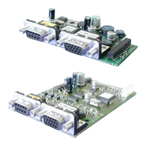
KEBCO ACOMBIVERT F5 X3A User manual

COMBIVERT
Instructions For Use COMBIVERT F5
Encoder Interface Channel 1 SIN/COS Channel 2 variable
Translation of the original manual
Document Part Version
20145744 GBR 00

2

3
Preface
Preface
The described hard- and software are developments of the KEB Automation KG. The
enclosed documents correspond to conditions valid at printing. Misprint, mistakes and
technical changes reserved.
Signal words and symbols
Certain operations can cause hazards during the installation, operation or thereafter.
There are safety informations in the documentation in front of these operations. Security
signs are located on the device or machine. A warning contains signal words which are
explained in the following table:
DANGER Dangerous situation, which will cause death or serious injury in case of
non-observance of this safety instruction.
WARNING Dangerous situation, which may cause death or serious injury in case of
non-observance of this safety instruction.
CAUTION Dangerous situation, which may cause minor injury in case of non-ob-
servance of this safety instruction.
Attention Situation, which can cause damage to property in case of non-obser-
vance.
RESTRICTION
Is used when certain conditions must meet the validity of statements or the result is
limited to a certain validity range.
Is used when the result will be better, more economic or trouble-free by follow-
ing these procedures.
More symbols
► Thisarrowstartsanactionstep.
• / - Enumerations are marked with dots or indents.
=> Cross reference to another chapter or another page.
Note to further documentation.
https://www.keb.de/de/service/downloads.html

4
Preface
Laws and guidelines
KEBAutomationKGconrmswiththeCEmarkandtheECdeclarationofconformity,
that our device complies with the essential safety requirements.
The CE mark is located on the name plate. The EC declaration of conformity can be
downloaded on demand via our website. Further information is provided in chapter
"Certication".
Warranty
The warranty on design, material or workmanship for the acquired device is given in the
current terms and conditions.
Hereyouwillndourcurrenttermsandconditions.
https://www.keb.de/de/agb.html
Furtheragreementsorspecicationsrequireawrittenconrmation.
Support
Through multiple applications not every imaginable case has been taken into ac-
count. If you require further information or if problems occur which are not treated de-
tailed in the documentation, you can request the necessary information via the local
KEB Automation KG agency.
The use of our units in the target products is beyond of our control and therefore
exclusively the responsibility of the machine manufacturer, system integrator or
customer.
Theinformationcontainedinthetechnicaldocumentation,aswellasanyuser-specic
advice in spoken and written and through tests, are made to best of our knowledge and
information about the application. However, they are considered for information only
without responsibility. This also applies to any violation of industrial property rights of a
third-party.
Selection of our units in view of their suitability for the intended use must be done gener-
ally by the user.
Tests can only be done within the application by the machine manufacturer. They
must be repeated, even if only parts of hardware, software or the unit adjustment
are modied.
Copyright
The customer may use the instruction manual as well as further documents or parts
from it for internal purposes. Copyrights are with KEB Automation KG and remain valid
in its entirety.
Other wordmarks or/and logos are trademarks (™) or registered trademarks (®) of their
respectiveownersandarelistedinthefootnoteontherstoccurrence.
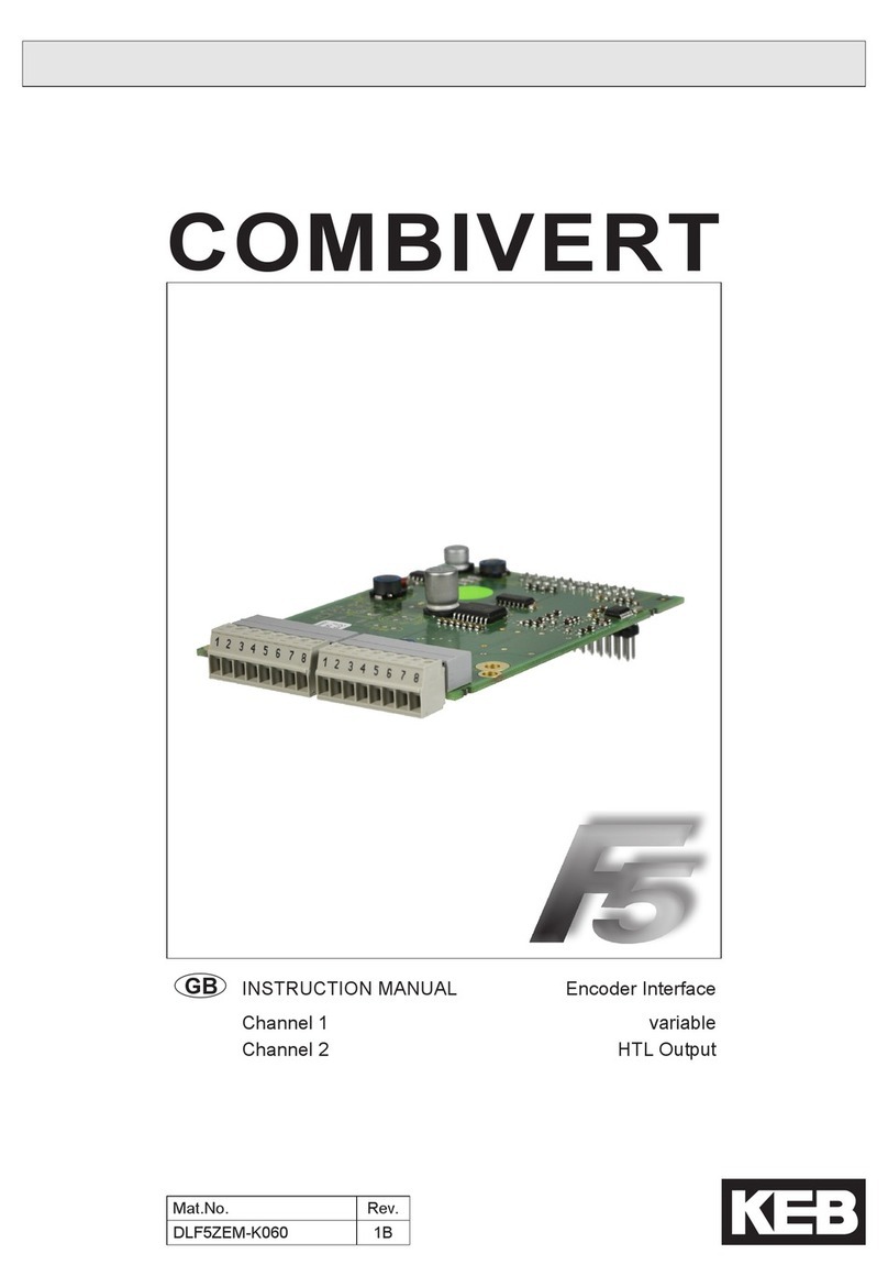
Table of contents
D - 5
2. Product description ....................................................................................... 6
2.1 General...............................................................................................................6
2.2 Material number .................................................................................................6
2.3 Scope of delivery (option or replacement delivery) ............................................6
2.4 Mechanical installation .......................................................................................7
3. Description of the Interface........................................................................... 7
3.1 Voltage supply....................................................................................................7
3.2 Channel 1 ...........................................................................................................8
3.2.1 Specications .....................................................................................................8
3.2.2 Description of X3A..............................................................................................8
3.2.3 Input signals .......................................................................................................8
3.2.3.1 Analog input signals ...........................................................................................9
3.2.3.2 Encoder monitoring ..........................................................................................10
3.2.4 Connection of the encoder ...............................................................................11
3.2.4.1 Encoder cabel at SUB-D15 ..............................................................................11
3.2.5 Encoder cable ..................................................................................................12
3.2.6 Encoder line length...........................................................................................12
3.2.7 Tested encoders...............................................................................................12
3.3 Channel 2 .........................................................................................................12
4. Start-up ....................................................................................................... 13
4.1 Parameter description ......................................................................................13
4.1.1 Encoder 1 status (Ec.37)..................................................................................13

SIN/COS at Channel 1
GB -6
2. Product description
Figure 1: SIN/COS at Channel 1
For housing size G…U For housing size D and E
X3A
Channel 1
X3B
Channel 2
X3A
Channel 1
X3B
Channel 2
X3B X3A
Channel 2 Channel 1
see material number SIN/COS
2.1 General
Each of the interface cards delivered by KEB include two interfaces. As there are numerous
different combinations available each interface will be described by means of separate in-
structions. The instruction comprises the installation of the interface card, the connection
as well as the start-up of a suitable encoder. Further information and the parameter adjust-
ments are described in the application manual for the inverter/servo.
2.2 Material number
xM F5 K8G X X X X
Term of deli-
very 0 installed Z Option, spare part
Interface
X3A
M TTL output 2036 N TTL input 2035
1 SSI-input 2021
F5 Series
applicable for housing size 1M D, E (circuit board 1M.F5.280-xxxx see above)
2M G…U (circuit board 2M.F5.280-xxxx see above)
2.3 Scope of delivery (option or replacement delivery)
• Encoder interface
• two instruction manuals
• xingbolt
• packing material

SIN/COS at Channel 1
GB -7
2.4 Mechanical installation
All kind of works on the inverter may be carried out by authorized personnel in accordance
with the EMC and safety rules only.
• Switch inverter de-energized and await capacitor discharge time
• Pull off operator
• Remove plastic cover
•Removexingbolt
• Fix interface board beginning from the socket connector straightly
•Screwinxingbolt
• Attach plastic cover
3. Description of the Interface
3.1 Voltage supply
Figure 3.1 Voltage supply of control and encoder interfaces
Uint 24VDC Internal voltage supply of COMBIVERT.
X2A
X3A
X3B
5,2V
24V
5V
24V
5V
Uint
Uext
Iint
120mA at Hiperface, Sin/Cos, EnDat, SSI-Sin/Cos
and UVW.
170mA at all other encoder interfaces.
Uext Control terminal strip (X2A) of the COMBIVERT with
external voltage supply 24…30DCV.
24V Voltage output of encoder interfaces X3A and X3B for
encoder supply.
I24V
Current Iint reduces itself by draw current to the 5V output
in accordance with the following formula:
5.2V x I5V
I24V = Iint - –––––––––
Uint
5V Voltage output for encoder supply. 5.2V are obtained
from the 24V voltage.
I5V
300mA at Hiperface, Sin/Cos, EnDat, SSI-Sin/Cos
and UVW.
500mA at all other encoder interfaces.
1A at external supply (dependent on the voltage
source)

SIN/COS at Channel 1
GB -8
3.2 Channel 1
3.2.1 Specications
X3A Socket SUB-D15
Interface type SIN/COS
Inputs / tracks 1Vss typical (0.6…1.2)
Limiting frequency 200kHz
Increments per re-
volution 1…2048inc (recommendation 1024 inc for speed upto 4500 rpm
Input resistance 120Ω
Max. line length 50m, the value is additionally limited by the signal frequency, cable
capacity and supply voltage (see chapter „encoder line length").
3.2.2 Description of X3A
Figure 3.2.2 Socket X3A
5 4 3 2 1
10 9 8 7 6
15 14 13 12 11
PIN Name Description
1 C- Signal input C- (difference signal to C+)
2 D- Signal input D- (difference signal to D+)
3 A- Signal input A- (difference signal to A+)
4 B- Signal input B- (difference signal to B+)
5 - -
6 C+ Absolute track for initial position and angular calculation
7 D+ Absolute track for initial position and angular calculation
8 A+ Incremental encoder input track A for counter and direction detection
9 B+ Incremental encoder input B for counter and direction detection
10 - -
11 24V Power supply for encoder
12 +5.25V Power supply for encoder
13 COM Reference potential for voltage supply
14 -R Signal input R- (difference signal to R+)
15 +R Zero track
– GND Connection for shield at the connector housing (is directly connected
with the inverter earth).
3.2.3 Input signals
Tracks C and D are giving an absolute signal to the control unit. The period is correspond
exactly to one mechanical revolution of the encoder. At starting the control unit will start
withthisrelativeinaccurateabsolutevalue.Withtherstzeropulsethepositionwillbecor-
rected. Thus approach to reference point is not necessary.

SIN/COS at Channel 1
GB -9
The output signals of tracks A and B are dependent on the encoder line number. If the en-
coder line number, adjusted in parameter Ec.01, is not correspond with the actual encoder
line number, an error will be triggered immediately after revolution of the rotor axis.
Thezerotrackwillpermanentlybecomparedwiththeposition.Incaseadierenceoccurs
thepositionwillbecorrectedwitharamptimeafteralter.Inadditionthepositionvalue
of the absolute track (C and D) will be compared with the position any 30 ms. Since the
absolute track is relatively inaccurate, corrections are only made until a valid zero signal is
recognized.Thenonlyanerrorisreleased,ifthedierenceexceedsamaximumvalue.
If no absolute and/or zero track is recognized during power-on, this functions are
getting deactivate. Operation with exclusively utilization of the high resolution
tracks A and B is possible.
3.2.3.1 Analog input signals
Figure 3.2.3.1 Signal tracks
360°electrical = 360°mechanical
360°mechanical
Increments per revolution
0V t
R
0V t
D
0V t
C
0V
A
t
0V
B
t
typically 1Vss
typically 1Vss
typically 1Vss
typically 1Vss
0.2…0.85V

SIN/COS at Channel 1
GB -10
3.2.3.2 Encoder monitoring
Parameter r/w Enter prog.
Ec.42 Encoder alarm mode yes no no
The encoder monitoring is a software function and dependent on the encoder type. The
absolute track is monitored approx. all 30 ms and the incremental track is monitored ap-
prox. all 16 ms. If the permissible signal levels are fallen below „Error! Encoder 1“ (value
32) is triggered. Dependent on the encoder type the response time can be 100 ms and
more.
Setting range Setting Meaning
0
1
Encoder monitoring off
1 Encoder monitoring on
2 Encoder monitoring on (open-loop off)
3 Warning

SIN/COS at Channel 1
GB -11
3.2.4 Connection of the encoder
3.2.4.1 Encoder cabel at SUB-D15
• Encoder cable double-shielded and twisted in pairs
• Connect exterior shielding at both ends to PE/GND
• Connect interior shielding at one side to COM
• Do not connect exterior and interior shielding
Figure 3.3.4.1 Connection of the encoder
Motor encoder plug Socket X3A
1
2
34
5
6
7
8
9
10
11
12
13
14
15
16
17
5 4 3 2 1
10 9 8 7 6
15 14 13 12 11
Name PIN PIN Core color
GND – – exterior shielding
A+ 1 8 green
A- 2 3 yellow
B+ 11 9 blue
B- 12 4 red
C+ 5 6 white
C- 6 1 brown
D+ 14 7 black
D- 4 2 purple
R+ 3 15 gray
R- 13 14 pink
COM 7 13 white/green
+5.25V 10 12 gray/pink

SIN/COS at Channel 1
GB -12
3.2.5 Encoder cable
KEBencodercablesarecorrespondingtothefollowingspecication:
Signal lines 4 x (2 x 0.14mm²)
Supply lines 2 x (0.5mm²)
Particularities trailing capable, oil resistant
Temperature range constant up to 80°C
Color green RAL 6018
Material number 00.S4.209-xxxx
3.2.6 Encoder line length
The maximum line length of the encoder cable is 50m. It results from the voltage drop of the
supply line. The value is calculated as follows:
Encoder line length = U - Umin
––––––––––
Imax • 2 • R
max. encoder current Imax: see encoder description
Supply voltage U: 5.2V
minimum input voltage Umin: see encoder description
KEB encoder cable resistance R: 0.036Ω/mat0.5mm²
3.2.7 Tested encoders
The following encoder can be used dependent on the interface and the control:
Manufacturer Type Encoder type
Heidenhain ERN1188 SIN/COS-encoder
However,thisdoesnotrestricttheuseofrotaryencoderswithsamespecicationsofother
manufacturers.
3.3 Channel 2
The description of input X3B is depending on the used encoder interface. It is described in
a separate manual.

SIN/COS at Channel 1
GB -13
4. Start-up
After installation or exchange of an encoder interface some adjustments of the inverter/
servo software have to be done before operation:
• Switch on inverter
• Select application mode
• When using synchronous motors set ud.2 to F5-S
• Select parameter Ec.00 and control whether „14: SIN/COS“ is displayed. The displa-
yedvaluehastobeconrmedby„ENTER“inanycase.
• Select parameter Ec.10 and carry out the same for the 2. encoder interface
• Depending on the encoder interface and control card (see 3.3.7) control/adjust the
number of increments per rev. (Ec.1), the SSI data code (Ec.43) and the SSI data
word length (Ec.44 and Ec.53).
• Select parameter Ec.01 and adjust increments per revolution
4.1 Parameter description
4.1.1 Encoder 1 status (Ec.37)
This parameter displays, by means of different status messages, the status of encoder and
interface. Dependent on the encoder only special messages are possible. All errors are only
set at control release, although they are already displayed in Ec.37.
Value Description
The following value is displayed at correct operation:
16 Position values are being transferred, encoder and interface are working
The following status messages triggers „Error Encoder Change“ (E.EncC) because the
correct evaluation of the position is no longer guaranteed.
Error E.EncC can only be reset via parameter Ec.0. Exception! An error due to wrong
increments per revolution (value 70) is reset immediately, if the correct increments per
revolution are adjusted (from software 2.7).
Attention, the modulation is released, when the control release is still set!
64 Encoder is unknown and will not be supported
67 The signals of the incremental track are not correct, e.g. no encoder is con-
nected or the encoder cable is defective.
68 The signals of the absolute track are not correct. The absolute track at Endat,
Hiperface and SSI-Sin/Cos is digital. The absolute track at Sin/Cos is analog.
69 Position deviation too high. The position determined by the incremental signals
and the absolute position (of absolute track, zero signal or serial selected) does
no longer correspond or cannot be corrected.
70 Increments per revolution adjusted in the inverter does not correspond with en-
coder increments per revolution.
71 Interface type is unknown: Interface has not been recognized.
75 Encoder temperature too high (message from encoder)
76 Rotary speed is too high (message from encoder)
further on next page

SIN/COS at Channel 1
GB -14
Value Description
77 Encodersignalsareoutsidethespecication(messagefromencoder)
78 Encoder has internal defect (message from encoder)
92 Encoder will be formatted. When writing an encoder with memory structures
differentfromtheKEB-denition,theirmemorieswillbere-organizedinsucha
manner that they can be written. This procedure can take some seconds, depen-
ding on the respective memory structure.
96 New value detected, because an another encoder is attached.
98 Interface is busy
The following status messages triggers „Error Encoder 1“ (E.Enc1), if encoder data is
read:
97 KEB-referenceisundened.Memorystructureoftheencoderdoesnotcorre-
spondtotheKEB-denitionandthereforedatacannotberead.Theencoderis
denedbywritingdata.AtF5-Stheerrorisresetasfollow:
• writing a position to Ec.2.
• perform a system position trimming
Following status messages trigger error „Error Hybrid“ (E.HYb):
0,255 No communication between interface and control card.

Notices
GB -15

KEB Automation KG
Südstraße 38 • D - 32683 Barntrup
Telefon +49 5263 401-0 • Telefax 401-116
KEB Antriebstechnik GmbH • Getriebemotorenwerk
Wildbacher Straße 5 • D - 08289 Schneeberg
Telefon +49 3772 67-0 • Telefax 67-281
GESELLSCHAFTEN
ÖSTERREICH
KEB Antriebstechnik Austria GmbH
Ritzstraße 8
A - 4614 Marchtrenk
Tel: +43 7243 53586-0
Fax: +43 7243 53586-21
E-Mail: info@keb.at
Internet: www.keb.at
CHINA
KEB Power Transmission
Technology (Shanghai) Co. Ltd.
No. 435 QianPu Road
Songjiang East Industrial Zone
CN-201611 Shanghai, PR. China
Tel: +86 21 37746688
Fax: +86 21 37746600
Internet: www.keb.cn
FRANKREICH
Société Française KEB SASU
Z.I. de la Croix St. Nicolas
14, rue Gustave Eiffel
F - 94510 LA QUEUE EN BRIE
Tel: +33 1 49620101
Fax: +33 1 45767495
Internet: www.keb.fr
GROSSBRITANNIEN
KEB (UK) Ltd.
5 Morris Close
Park Farm, Industrial Estate,
Wellingborough
GB - Northants, NN8 6 XF
Tel: +44 1933 402220
Fax: +44 1933 400724
E-Mail: info@keb.co.uk
Internet: www.keb.co.uk
ITALIEN
KEB Italia S.r.l. Unipersonale
Via Newton, 2
I - 20019 Settimo Milanese (Milano)
Tel: +39 02 3353531
Fax: +39 02 33500790
E-Mail: info@keb.it
Internet: www.keb.it
JAPAN
KEB - Japan Ltd.
15 - 16, 2 - Chome
Takanawa Minato-ku
J - Tokyo 108 - 0074
Tel: +81 33 445-8515
Fax: +81 33 445-8215
Internet: www.keb.jp
RUSSLAND
KEB RUS Ltd.
Lesnaya str, house 30
Dzerzhinsky (MO)
RUS - 140091 Moscow region
Tel: +7 495 6320217
Fax: +7 495 6320217
E-Mail: info@keb.ru
Internet: www.keb.ru
USA
KEB America, Inc
5100 Valley Industrial Blvd. South
USA - Shakopee, MN 55379
Tel: +1 952 2241400
Fax: +1 952 2241499
Internet: www.kebamerica.com
Repräsentanzen
• Belgien
• Brasilien
• Korea
• Spanien
Weitere Partner für …
Ägypten • Australien • Belgien • Bulgarien • Dänemark • Griechenland • Indien • Indonesien • Iran • Israel • Malaysia
Marokko • Neuseeland • Niederlande • Pakistan • Polen • Portugal • Rumänien • Schweden • Schweiz • Singapur
Slowakei • Spanien • Südafrika • Taiwan • Thailand • Tunesien • Tschechien • Türkei • Ungarn • Usbekistan
… unter www.keb.de/de/kontakt/keb-weltweit.html
Document 20145744
Part/Version GBR 00
Date 2017-01-20
Headquarter
This manual suits for next models
2
Table of contents
Other KEBCO Recording Equipment manuals

KEBCO
KEBCO F5 Series User manual

KEBCO
KEBCO COMBIVERT F5 User manual

KEBCO
KEBCO COMBIVERT F5 User manual

KEBCO
KEBCO COMBIVERT F5 User manual

KEBCO
KEBCO COMBIVERT F5 User manual

KEBCO
KEBCO COMBIVERT F5 User manual

KEBCO
KEBCO COMBIVERT F5 User manual

KEBCO
KEBCO COMBIVERT F5 User manual

KEBCO
KEBCO COMBIVERT F5 User manual

KEBCO
KEBCO COMBIVERT F5 User manual