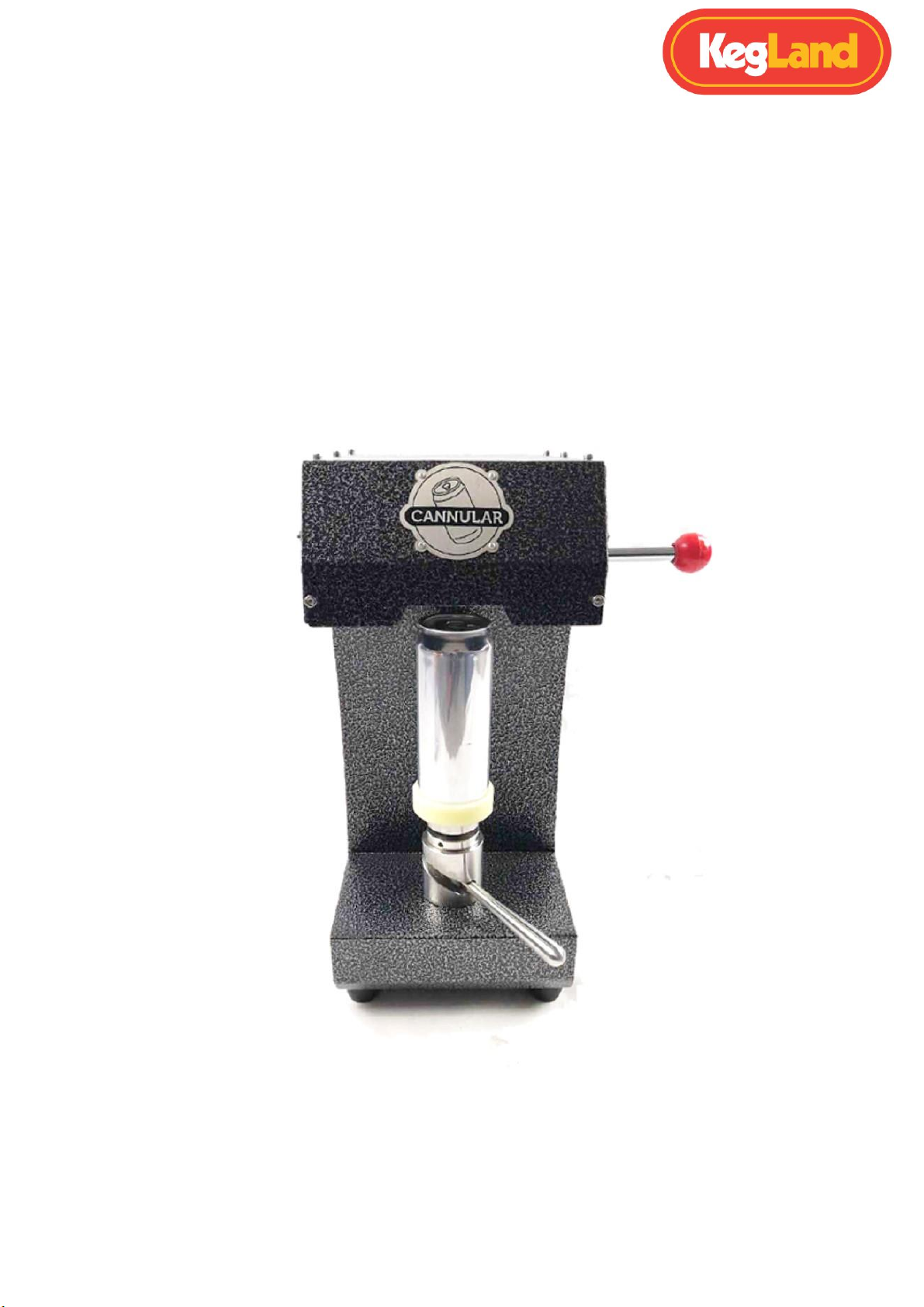
Cannular Compact Canning Machine Instruction Manual
Page 4of 27 www.KegLand.com.au Last Updated 4/03/2021 2:06 PM
Your Cannular is calibrated and set up at the factory to seam KegLand 500mL B64 cans
(KL05449, KL18517 and KL15684), however, due to an extended transit time it may have
shifted out of specification during its journey. Before making any adjustments to the seamer
follow the following initial start-up instructions:
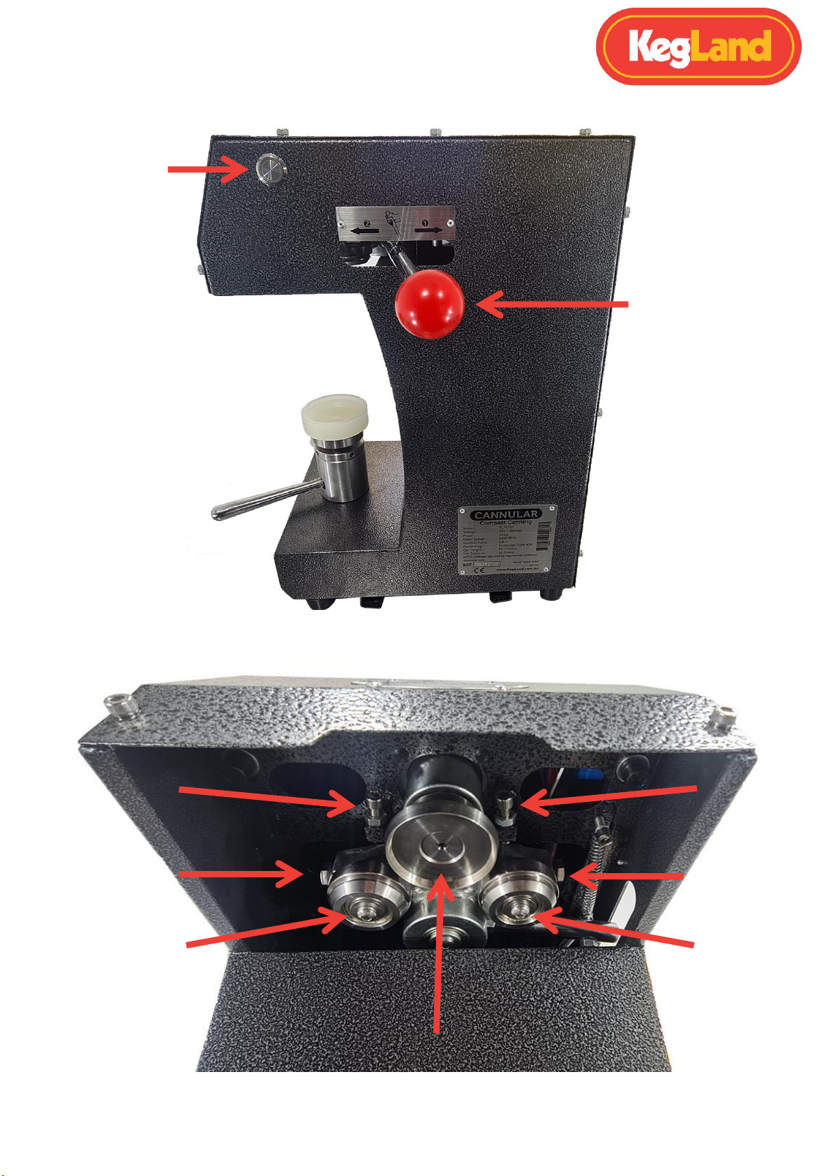
1. Remove the top of the Cannular to improve access to the chuck and rollers.
2. With the Cannular unplugged from the power supply, push and the lever forward
(operation 1 position). While holding the lever in this position manually rotate the 1st
operation roller and look/listen for any signs of the roller containing the chuck.
Repeat this for the 2nd operation roller by pulling and holding the lever back. If either
roller contacts the chuck then adjust the position of the rollers according to the
measurements on pages 14-18.
IMPORTANT: Under no circumstances allow the rollers to come into contact with the
chuck. As these are both made from hardened steel and both require high tolerances.
Both chuck and rolls can quickly get damaged if they are to come into contact. Prior to
seaming a can hold the lever in position one and turn the 1st operation roller with your
hand and make sure that the 1st operation roller never comes into contact with the chuck
at any point in time. Repeat this with the 2nd operation roller.
3. Once you have confirmed that the rollers do not contact the chuck, fill a can with
soda water or any other carbonated beverage, and place the lid on the full can.
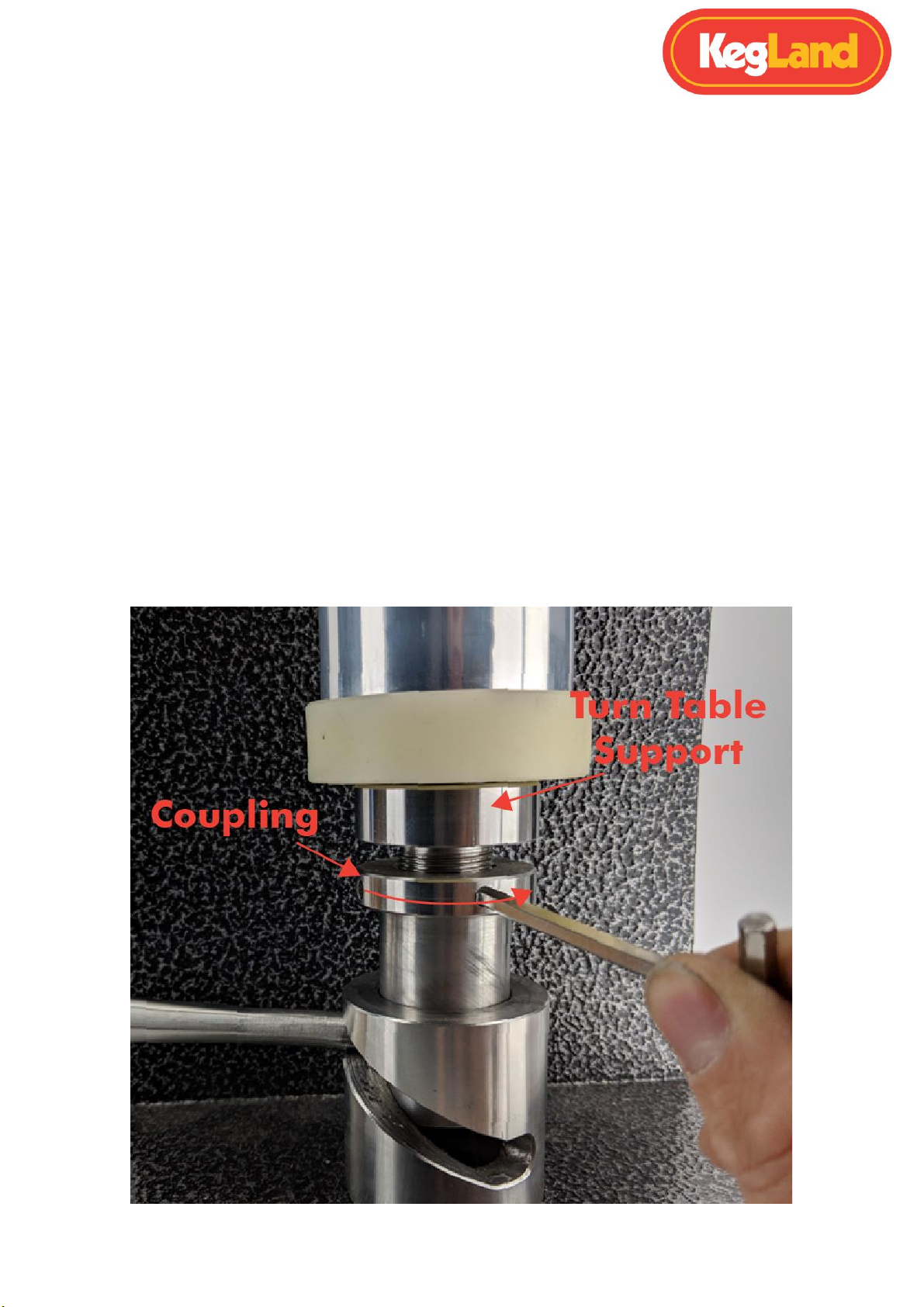
4. Place the correct table spacer for your specific can onto the turntable, then plug the
Cannular into the power supply.
5. Raise the table and ensure the can and can lid are held firmly concentrically into the
chuck.
6. Press the power switch on the Cannular.
7. Push and hold the lever forward for 1 second and then pull and hold the lever back
for 1 second. Holding for too long in either direction can result in an incomplete or
damaged seam.
8. If it is determined that the seam leaks then calibrate the Cannular according to the
instructions on pages 14-27.