FGZ201ELF2/ERF2
8
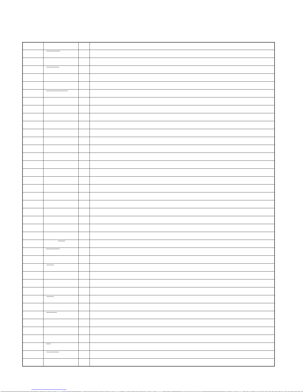
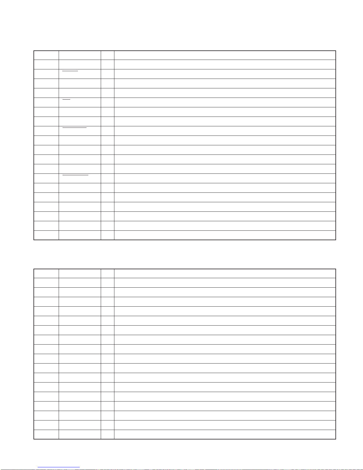
Pin No. Pin Name I/O Purpose / Description / Processing / Operation
42 SHCON O Graphic microprocessor standby control output
43 SHSTBY I The completion input of graphic microprocessor standby shift
44 SYSCS O System microprocessor Request-to-Send output
45 SH_VMUTE I Graphic microprocessor image muting demand input
46 CE I Flash write-in CE input
47 TOUCH_EN O Graphic microprocessor touch key analysis permission output
48 TOUCH I Notice input of graphic microprocessor touch key-on
49 PLLCE O The clock generating IC mode output for Q2i
50 PLLSDA O The clock generating IC data output for Q2i
51 PLLSCK O The clock generating IC clock output for Q2i
52 BL-ON O Back light switch output
53 VIDEO Swa O TV/REAR changeover switch output
54 NC - Un-connecting
55 VIDEO SWb O DVD changeover switch output
56 SYNC Swa O VIDEO/NAVI SYUn-connecting changeover switch output
57 SYNC SWb O GRAPHICS SYUn-connecting changeover switch output
58 VIDEO SWc O DVD-CH/NAVI-AUX changeover switch output
59 VIDEO SWd O AUX changeover switch output
60 HPOSI1 O Level position adjusted power
61 HPOSI2 O Level position adjusted power
62 VCC - Power supply
63 SCAN1 O Screen mode changeover switch output
64 VSS - Ground
65 SCAN2 O Screen mode changeover switch output
66 NTSC/PAL O NTSC/PAL changeover switch output
67 VMUTE O Video muting control output
68 +BDET SW O +B voltage detector circuit control output
69 REV I Reverse detection input
70 PARKING I Parking detection input
71 P-ON O Power supply control output
72 FAULT O FAULT display output
73 ACC I ACC voltage detection input
74 BUDET I +B voltage variation detection input
75 SHCS I Graphic microprocessor Request-to-Send input
76 IGN I Ignition voltage detection input
77 ADA-INT O NAVI voice changeover switch output
78 AUDIO-MUTE O AUDIO muting signal output
79 TV O TV voice muting output
80 MUTE1 O MUTE1 signal output
81 TYPE0 I It forces and is a setting input
MICROCOMPUTER’STERMINAL DESCRIPTION