KFI A3000 Manual

Model#: A3000
Owner’sManualandOperatingInstructions
3000lb.
ATVWINCH

Table of Contents
Introduction ..................................... 1
Accessories................................................ 1
This Booklet.............................................. 1
Manual Conventions.........................2
Safety Rules......................................3
Controls and Features.......................5
Winch........................................................5
Installation.......................................6
Step 1-Mount the Winch...........................6
Step 2-Mount the Contactor.....................6
Step 3-Mount the Handlebar Switch .......6
Step 4-Mount the Hand Remote Socket
(Optional) .................................................7
Step 5-Wiring the Winch..........................7
Winch Wiring Diagram......................8
Switch Wiring Diagram ....................9
Operation .......................................10
General Tips for Safe Operation.............10
Self Recovery ..........................................10
Winching Techniques A-Z.......................11
Maintenance................................... 12
Lubrication ............................................. 12
Cable Assembly Replacement ................ 12
A3000 Specifications...................... 13
Performance Specifications.................... 13
Winch Diagram....................................... 14
Model: #A3000 ...................................... 14
Winch Parts List ..................................... 15
Troubleshooting ............................. 16
PLOWING ALERT........................... 16
Warranty........................................ 17
Warranty Qualifications..........................17
Repair/Replacement Warranty...............17
Do not return the unit to the place of
purchase...................................................17
Warranty Exclusions ...............................17
Normal Wear........................................17
Installation, Use and Maintenance .....17
Other Exclusions..................................17
Limits of Implied Warranty and
Consequential Damage............................17
Contact Information............................... 18
Address................................................ 18
Corporate ............................................ 18
Customer Service ................................ 18
Technical Service ................................ 18
Agreement...................................... 18
Notes .............................................. 19

Introduction
A3000 1
Introduction
Congratulations on your purchase of a KFI
winch. KFI researches and develops winches
to strict specifications. With proper use and
maintenance, this winch will bring years of
satisfying service.
Accessories
Kappers Fabricating Inc. manufactures,
purchases and sells accessories designed to
help you get the most from your purchase.
This Booklet
Every effort has been made to ensure the
accuracy and completeness of the
information in this manual. We reserve the
right to change, alter and/or improve the
product and this document at any time
without prior notice.

Manual Conventions
2 A3000
Manual Conventions
This manual uses the following symbols to
help differentiate between different kinds of
information. The safety symbol is used with
a key word to alert you to potential hazards
in operating and owning a winch.
Follow all safety messages to avoid or reduce
the risk of serious injury or death.
DANGER
DANGER indicates an imminently hazardous
situation which, if not avoided,
will
result in death
or serious injury.
WARNING
WARNING indicates a potentially hazardous
situation which, if not avoided,
could
result in
death or serious injury.
CAUTION
CAUTION indicates a potentially hazardous
situation which, if not avoided,
may
result in
minor or moderate injury.
CAUTION
CAUTION used without the safety alert symbol
indicates a potentially hazardous situation which,
if not avoided,
may
result in property damage.

Manual Conventions
A3000 3
Safety Rules
WARNING
Read this manual thoroughly before operating
your winch. Failure to follow instructions could
result in serious injury or death.
WARNING
Do not exceed the rated capacity.
DANGER
Do not use this winch for lifting or moving people
or animals.
DANGER
Keep yourself and others a safe distance to the
side of the cable when under tension.
DANGER
Never step over a cable or near a cable under
load.
WARNING
The wire rope may break before the motor stalls.
For heavy loads at or near rated capacity, use a
pulley block/snatch block to reduce the load on
the wire rope.
WARNING
Do not move the vehicle to pull a load (towing)
on the winch cable. This could result in cable
breakage.
WARNING
Pull only on areas of the vehicle as specified by
the vehicle manufacturer
WARNING
Do not use the winch to secure or hold a vehicle
for a long period of time. Do not use the winch to
secure a vehicle for transport.
WARNING
Disconnect the remote control and battery leads
when not in use for extended periods.
WARNING
Avoid “shock loads” by using the control switch
intermittently to take up the slack in the wire
rope. “Shock loads” can far exceed the rate
capacity for the wire rope and drum.
Do not accelerate your vehicle while winching.
Loss of traction can cause a shock load on the
cable. Do not use cable as a pull strap.

Safety Rules
4 A3000
WARNING
Batteries contain acid and produce explosive
gases.
Keep sparks, flames and cigarettes away from
batteries at all times. Wear safety glasses and
protect the eyes at all times. Do not lean over
the batteries during operation.
WARNING
When re-spooling the cable, ensure that the
cable spools in the under-wind position with the
cable entering the drum from the bottom, not the
top.
To re-spool correctly, and while wearing gloves,
keep a slight load on the cable while pushing the
remote button to draw in the cable. Walk toward
the winch not allowing the cable to slide through
your hands. Do not let your hands get within 12”
of the winch while re-spooling. Turn off the
winch and repeat the procedure until a few feet
of cable is left. Disconnect the remote control
and finish spooling by rotating the drum by hand
with the clutch disengaged. Keep hands clear of
the fairlead and drum while the winch is under
power.
WARNING
Do not use as a hoist. Do not use for overhead
lifting.
CAUTION
Use gloves to protect hands when handling the
cable. Never let the cable slide through your
hands.
CAUTION
Do not wrap the cable around any object and
hook it back onto itself.
CAUTION
Apply blocks to the wheels of the vehicle when
on an incline.
CAUTION
Duration of winching pulls should be kept as
short as possible.
If the motor becomes uncomfortably hot to the
touch, stop winching immediately and let it cool
down for a few minutes. Do not pull for more
than one minute at or near the rated load.
CAUTION
If the motor stalls, do not maintain power to the
winch.
Electric winches are designed and made for
intermittent use and should not be used in
constant duty applications.
CAUTION
Never release the free-spool clutch when there is
a load on the winch.
CAUTION
Use hook strap when handling the hook for
spooling or unspooling the wire rope.

A3000 5
12
11
10
9
8
6
2
7
5
4
3
1
6
Controls and Features
Read this owner’s manual before operating your winch. Familiarize yourself with the location and
function of the controls and features. Save this manual for future reference.
Winch
Motor (1): 1.3HP 12V DC motor provides
power to the planetary gear mechanism.
Winch Drum (2): The winch drum is the
cylinder on which the wire rope is stored. It
can feed or wind the rope depending on the
remote winch switch.
Wire Rope (3): 3/16” x 45.9’ galvanized
aircraft cable designed specifically for load
capacity of 3,00lbs. (44 useable feet with five
wraps on the drum). The wire rope feeds
onto the drum in the “under wind” position
through the roller fairlead (4) and is looped
at the end to accept the clevis hook pin (12).
Roller Fairlead (4): When using the
winch at an angle the roller fairlead acts to
guide the wire rope onto the drum and
minimizes damage to the wire rope from
abrasion on the winch mount or bumper.
Free spooling Clutch (5): The clutch
allows the operator to manually disengage
(“FREESPOOL”) the spooling drum from
the gear train. Engaging the clutch
(“ENGAGE”) locks the winch into the gear
system.
Braking System (6): Braking action is
automatically applied to the winch drum
when the winch motor is stopped and there
is a load on the wire rope.
Planetary Gear System (7): The
reduction gears convert the winch motor
power into extreme pulling forces. This
system allows high torque while maintaining
compact size and light weight.
Rocker Switch (8): Rocker switch with
handlebar mount for powering the rope in or
out of your winch drum.
Hand Held Switch (9): Hand held switch
with a remote socket for powering the rope
in or out of your winch drum.
Fairlead Mount (10): Adapter to mount
the winch and fairlead for utility
applications.
Contactor (11): Power from the vehicle
battery flows through the weather sealed
solenoid switch before being directed to the
winch motor.
Clevis Hook (12): Provides a means for
connecting the looped ends of cables to an
anchor.

Installation
6 A3000
Installation
This KFI 3,000 lb winch is designed with a
bolt pattern that is standard in this class of
winch. Many winch mounting kits are
available that utilize this bolt pattern for the
most popular ATV’s and UTV’s.
Step 1-Mount the Winch
WARNING
Before you start to install this winch, disconnect
the vehicle ground and positive leads from the
battery.
1. Install the winch and fairlead with the
supplied hardware per the instructions
provided with the model specific
mounting kit or prepare a flat, secure
mounting location for the winch.
NOTE
If you choose not to use a model specific
mounting kit, you will need to drill holes in the
structural support of the vehicle. Be certain that
your structural support will stand up to the
pulling forces of this winch.
CAUTION
Mounting bolts must be SAE grade 5 or better
and torque to 17 ft. lbs.
2. Attach the winch using the M8 x 25 bolts
and washers through the fairlead
bracket or model specific mount and
then into the winch.
3. Disengage the clutch by rotating the
clutch cap to the “FREESPOOL”
position. Release the wire rope and pull
through the roller fairlead.
4. Attach the clevis hook and hand strap to
the cable.
Step 2-Mount the Contactor
1. Find a location for the contactor. If the
Model specific mounting kit does not
indicate a recommended contactor
location, then it is recommended that
the contactor be mounted close to the
battery in a clean dry location. Make
sure the location you chose allows
sufficient clearance from all metal
components. Drill mounting holes if
required. Once location is found do not
install until all wiring is completed.
Step 3-Mount the Handlebar
Switch
1. The switch is usually installed on the left
handlebar.
2. Use a piece of electrical tape around the
handlebar to help prevent rotation of the
mount on the handlebar. Do NOT
tighten over any hoses or cables.
3. Once your switch is mounted you can
route the wires back to where your
contactor is located.
4. Splice the end of the red wire to an
ignition (keyed) controlled power source
using the supplied wire splice. You may
need to use a test light to locate a
suitable wire. The wire should only have
power when the key is in the ON
position.
5. Make sure the handlebars have full
range of motion and then secure the
switch’s cable with the supplied cable
ties.
Not to scale. Do NOT use as a tem
p
late
1"
3/16"
1 5/8"
13/16"

Installation
A3000 7
Step 4-Mount the Hand
Remote Socket (Optional)
1. Determine a mounting location for the
hand remote socket. Make sure the area
behind your selected location is clear.
2. Drill the three holes as shown in the
figure on page 6 and install using the
supplied hardware. You can use the
rubber cap as a template.
3. Once your remote socket is mounted you
can route the wires back to where your
contactor is located.
4. Splice the end of the red wire to an
ignition (keyed) controlled power source
using the supplied wire splice. You may
need to use a test light to locate a
suitable wire. The wire should only have
power when the key is in the ON
position.
5. Secure the cable with the supplied cable
ties
Step 5-Wiring the Winch
CAUTION
Never route electrical cables across any sharp
edges, through or near moving parts, or near
parts that become hot
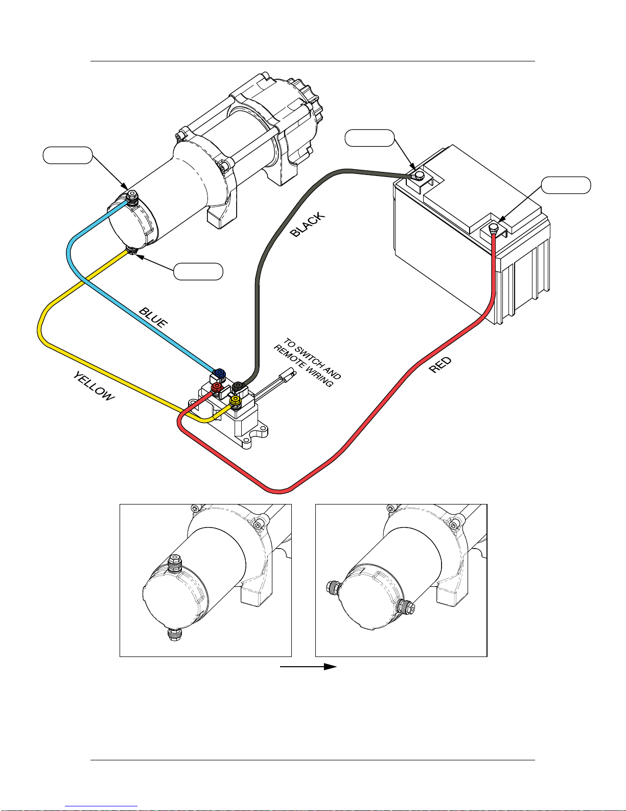
CAUTION
When attaching wires to the motor or contactor
terminals, hold the inner nut with a wrench while
tightening the outer nut with a second wrench.
Do NOT allow the terminals to rotate in their
housings. Rotation may cause internal wire
breakage or grounding. See Proper Terminal
Tightening Figure.
NOTE
Depending on the location of the contactor, you
may need to use the black and red cables in
place of the yellow and blue, and the yellow and
blue in place of the red and black. Just
remember that this also changes the diagram.
1. Connect the yellow and blue cables to
the motor terminals on the winch. Note
caution above. Route the other ends to
the contactor location.
(See diagram on page 8)
2. Connect the yellow and blue cables to
the contactor (yellow to yellow and blue
to blue). Do NOT tighten nuts.
(See diagram on page 8)
3. Connect the red and black cables to your
contactor (red to red and black to black).
Do NOT tighten nuts. Route the other
ends to your battery location.
(See diagram on page 8)
4. Connect the Handle bar switch to the
contactor. (black to black and green to
green) (See diagram on page 9)
NOTE
If you are installing the remote socket along with
the handlebar switch you will need to connect
the remote socket to the contactor and then the
handlebar switch to the remote socket.
(See diagram on page 9)
5. Once all wiring is connected to the
contactor you can then mount it using
the supplied M6 hardware.
6. Torque the contactor terminal nuts to
4.5 N-m (40 lb-in). Do NOT over
tighten.
7. Place all terminal boots over terminals
and secure all cables with zip ties or
electrical tape.
8. Connect the battery leads from the
contactor to the ATV’s Battery (red to
red and black to black)
(See diagram on page 8)
CAUTION
Battery cables should not be drawn taut. Leave
some slack for cable movement.
9. Check for proper drum rotation. Turn
the clutch cap to the “FREESPOOL”
position. Pull out some cable from the
drum, and then turn the clutch cap to
the “ENGAGE” position to engage the
gears. Make sure your machine is
running and press the cable out button
on the switch. If the drum is turning and
releasing more cable, then your
connections are accurate. If the drum is
turning and collecting more cable, then
reverse the leads on the motor. Repeat
and check rotation.
Proper
Terminal
Tightening

Installation
8 A3000
NEG(-)
POS(+)
NEG(-)
POS(+)
LEADS AT DEFAULT POSITION LEADS ROTATED 90°
W
inch Wiring Diagram

Installation
A3000 9
Switch Wiring Diagram

Operation
10 A3000
Operation
General Tips for Safe
Operation
Your A3000 winch is rated at 3,000 lbs.
capacity in first layer (max) when spooling
the first rope layer on the drum. Overloads
can damage the winch, motor and/or wire
rope. For loads over 2,300 lbs. we
recommend the use of the pulley
block/snatch block to double the wire rope
line. The will aid in two ways:
a) reduce the number or rope layers on the
drum, as well as,
b) reduce the load on the wire rope by as
much as 50%.
When doubling the line back to the vehicle,
attach to the tow hook, frame or other load
bearing part.
The vehicle engine should be kept running
during operation of the winch to minimize
battery drain and maximize power and
speed of the winch. If the winch is used for a
considerable time with the engine off the
battery may be drained and too weak to
restart the engine.
Get to know your winch before you actually
need to use it. We recommend that you set
up a few test runs to familiarize yourself
with rigging techniques, the sounds your
winch makes under various loads, the way
the cable spools on the drum, etc.
Inspect the wire rope and equipment before
each use. A frayed or damaged rope should
be replaced immediately. Use only
manufacturer’s identical replacement rope
with the exact specifications.
Inspect the winch installation and bolts to
ensure that all bolts are tight before each
operation.
Store the remote control inside your vehicle
in a place that it will not be damaged.
Any winch that appears to be damaged in
any way, is found to be worn, or operates
abnormally MUST BE REMOVED FROM
SERVICE UNTIL REPAIRED. It is
recommended that the necessary repairs be
made by a manufacturer’s authorized repair
facility.
Pull only on areas of the vehicle as specified
by the vehicle manufacturer.
Only attachments and/or adapters supplied
by the manufacturer are to be used.
Self Recovery
Locate a suitable anchor such as a strong
tree trunk or boulder. Always use a sling as
an anchor point.
Your winch is equipped with a roller fairlead
to help guide the wire rope and to reduce
binding on short side pulls.
Do not winch from an acute angle as the
wire rope will pile up on one side of the
drum causing damage to wire rope and the
winch.
Short pulls from an angle can be used to
straighten the vehicle. Long pulls should be
done with the wire rope at a 90° angle to the
winch/vehicle.
When pulling a heavy load, place a winch
saver, blanket or jacket over the wire rope
five or six feet from the hook.
In the event of a broken cable it will dampen
the snap back. For additional protection
open the hood of the vehicle.
For pulls over 2,300lbs., we recommend the
use of the snatch block/pulley block to
double line the wire rope.
This reduces the load on the winch and the
strain on the rope by approximately 50%

Operation
A3000 11
Winching Techniques A-Z
a. Take time to assess your situation and
plan your pull.
b. Put on gloves to protect your hands.
c. Disengage the clutch to allow free-
spooling and also save battery power.
d. Attach the hook strap to the clevis hook.
e. Pull out the wire rope to your desired
anchor point using the hook strap.
f. Secure the clevis hook to the anchor
point: Sling, chain or snatch block. Do
not attach the hook back onto the wire
rope.
g. Engage the
clutch.
h. Start your engine to ensure power is
being replenished to the battery.
i. Power in the wire rope guiding the wire
under tension to draw up the slack in
the wire. Once the wire is under tension,
stand clear. Never step over the wire
rope.
j. Double check your anchors and make
sure all connections are secure.
k. Inspect the wire rope. Make sure there
are at least 5 wraps of wire rope around
the winch drum.
l. Drape a blanket or jacket over the wire
rope approximately 5 to 6 feet from the
hook.
m. Clear the area. Make sure all spectators
stand clear and that no one is directly in
front or behind the vehicle or anchor
point.
n. Begin winching. Be sure that the wire
rope is winding evenly and tightly
around the drum. The vehicle that is
being winched can be slowly driven to
add assistance to the winching process.
Avoid shock loads; keep the wire rope
under tension.
o. The vehicle to be winched should be
placed in neutral and the parking brake
released. Only release the brake pedal
when under full tension. Avoid shock
loads to the winch. This can damage the
winch, rope and vehicle.
p. The winch is meant for intermittent use.
Under full load with a single line rig do
not power in for more than a minute
without letting the motor cool down for
a few minutes and then resume the
winching operation.
q. The winching operation is complete
once the vehicle is on stable ground and
is able to drive under its own power.
r. Secure the vehicle. Be sure to set the
brakes and place the vehicle in park.
s. Release the tension on the wire rope.
The winch is not meant to hold the
vehicle for long periods of time.
t. Disconnect the wire rope from the
anchor.
u. Rewind the wire rope. Make sure that
any wire already on the drum has
spooled tightly and neatly. If not, draw
out the wire and re-spool from the point
where the rope is tight.
v. Keep your hands clear of the winch
drum and fairlead as the wire rope is
being drawn in.
w. Secure the hook and hook strap.
x. Disconnect the remote control and store
in a clean, dry place.
y. Clean and inspect connections and
mounting hardware for next winching
operation.
z. Never use the winch as a tie down.

Maintenance
12 A3000
Maintenance
The owner/operator is responsible for all
periodic maintenance.
WARNING
Never operate a damaged or defective winch.
WARNING
Improper maintenance will void your warranty.
Complete all scheduled maintenance in a
timely manner. Correct any issue before
operating the winch.
Lubrication
All moving parts within the Electric Winch
have been Lubricated using high
temperature lithium grease at the factory.
No internal lubrication is required under
normal conditions. If the winch is subjected
to extreme conditions lubrication may be
required using a high temperature lithium
grease. Lubricate Cable Assembly (4)
periodically using a light penetrating oil.
Cable Assembly
Replacement
It is recommended that any modifications be
performed by a manufacturer’s authorized
repair facility, and that only manufacturer-
supplied parts be used
1. Rotate the clutch cap to the “Free Spool”
position.
2. Extend Cable Assembly to its full length.
Note how the existing cable is connected
to the inside of the drum.
3. Remove old Cable Assembly and attach
new one.
4. Rotate the clutch cap to the “Engage”
position.
5. Retract Cable Assembly onto drum
being careful not to allow kinking or
over heating of the winch.

A3000 Specifications
A3000 13
A3000 Specifications
Performance Specifications
Rated Pull 3,000 lbs (1361 kg)
Gear Reduction Ratio 171:1
Motor Permanent Magnet
1.3 HP/1.12 KW (DC 12V)
Drum Size 1.5” (D) x 3.32” (L)
38 mm (D) x 84.4 mm (L)
Cable 3/16” (D) x 45.9’ (L)
4.8 mm (D) x 14 m (L)
(44 useable feet with five
wraps on the winch drum)
Weight 24.8 lbs. (11.25 kg) (complete kit)
Height 4.2 inches (107 mm)
Width 4.06 inches (103 mm)
Length 12.67 inches (322 mm)
Bolt Pattern 4-7/8” x 3” (124mm x 76 mm)
Line speed and Motor Current (First layer)
Line pull Max lbs 0 500 1000 1500 2000 2500 3000
kgs 0 227 454 680 907 1134 1361
Line speed
(12VDC) FPM 10.2 9.51 8.86 7.87 6.56 5.58 4.27
MPM 3.1 2.9 2.7 2.4 2.0 1.7 1.3
Max Current amps 8 30.8 51.3 80.2 103.5 129 160.8
Cooling Time minutes 5 5 5 5 5 5 5
Line pull and cable capacity
Layers of cable on drum 1 2 3 4 5
Max pulling capacity per
layer lbs 3000 2450 2070 1793 1581
kgs 1361 1112 940 814 717
Cable capacity
per layer ft 7.15 15.45 24.7 34.5 45.9
m 2.18 4.71 7.52 10.52 14
* Use double line and snatch block for pulling loads over 2,300lbs / 1043.26 kgs..

A3000 Specifications
14 A3000
Winch Diagram
Model: #A3000

A3000 Specifications
A3000 15
Winch Parts List
No. Part # Description Qty
1 300100-C Motor Assembly 1
2 300001 Screw M6 x 20 4
3 300002 Washer -Flat Φ6 6
4 300003 Tie Bar 2
5 300004 Bushing Shaft 1
6 300005 Coupling Shaft 1
7 300006 Set Screw M5 x 8 1
8 300007 Drum 1
9 ATV-CBL-3K Cable Assembly 1
10 300008 Rear Bush Drum 1
11 300009 Front Thrust Washer 1
12 300010 Gear Ring Output 1
13 300300 Gear Carrier Assembly 1
14 300011 Retaining Ring Clip 1
15 300012 Spring 1
16 300013 Cover Clutch Housing 1
17 300014 Cap Screw M6 x 70 2
18 GB2760BB160
02-SS Radial Ball Bearing
16002 Sealed 1
19 300016 Clutch Cap 1
20 300017 Locking Washer Φ6 1
21 300018 Cap Screw M6 x 16 1
22 300019 Axis Support Bushing 1
23 GB2760BB060
02-SS Radial Ball Bearing
6002 Sealed 1
24 300021 Clutch Bushing 1
25 300022 Above Clutch Axis
Washer 1
26 300023 Cam Clutch Gear 1
27 300024 Gear Housing / End
Bearing 1
28 300025 Gear Ring 1
29 300062 Wire Tap 2
30 A-WIRES-WIN Winch Wires 2
31 100495 Standard Roller Fairlead
Bracket 1
32 ATV-RF Roller Fairlead 1
33 300030 Hand Saver Strap 1
34 ATV-CONT Contactor 1
35 ATV-MR Mini Rocker Switch 1
36 300032 Hex Hd Bolt M8 x 25 4
37 300063 Locking Washer Φ8 4
38 300033 Screw M10 x 20 2
39 300035 Locking Washer Φ10 2
40 300036 Nut M10 2
41 300061 Terminal Protector 8
42 300045 Handlebar Switch
Clamp 2
43 300046 Handlebar Switch
Extender 1
No. Part # Description Qty
44 300047 Handlebar Switch
Mounting Angle 1
45 300048 Screw M5 x 25 4
46 300049 Washer -Flat Φ5 5
47 300050 Locking Washer Φ5 3
48 300051 Screw M5 x 18 1
49 300052 Nut M5 3
50 300053 Screw #6-32 x 9/32” 2
51 300054 Locking Washer #6 2
52 A-WIRES-BAT Battery Wires 2
53 SE-HOOK Clevis Hook 1
54 300065 Screw M6 x 25 4
55 300066 Washer -Flat Φ6 4
56 300067 Locking Washer Φ6 4
57 300068 Nut M6 4
58 300069 Screw M6 x 1.0 x 20 2
59 300070 Washer -Flat Φ8 4
60 ATV-HR Hand Remote Assembly 1
61 300064 Hand Remote 3 Pins
Connector 1
62 300071 Nut M5 2
63 300072 Gasket 1

Troubleshooting
16 A3000
Troubleshooting
Problem Cause Solution
Motor does not turn on Switch Assembly not connected properly Insert Switch Assembly all the way into
the connector.
Loose battery cable connections Tighten nuts on all cable connections.
Contactor malfunctioning Tap Contactor to loosen contacts. Apply
12 volts to coil terminals directly. A
clicking indicates proper activation.
Defective Switch Assembly Replace Switch Assembly.
Broken Motor Leads. Over tightened
leads and broke internal wire connection.
May have also broken Isolator
Pull End-Cap off and check terminal solder
joint and plastic isolator. Get a
replacement End-Cap #A-CAPKIT
Defective motor Check for voltage at armature port with
Switch pressed. If voltage is present,
Replace motor.
Water has entered motor Allow to drain and dry. Run in short bursts
without load until completely dry.
Motor runs but Cable drum
does not turn Clutch not engaged Rotate clutch cap to the "Engage"
position. If problem persists, a qualified
technician needs to check and repair.
Motor runs slowly or
without normal power Insufficient current or voltage The battery is weak, recharge. Run winch
with vehicle motor running (Battery
should have a strong charge)
Loose or corroded battery cable
connections. Clean, Tighten, or replace.
Worn Brushes Replace Worn Brushes
Motor overheating winch running time too long Allow winch to cool down periodically.
Motor runs in one direction
only Defective or stuck Contactor Tap Contactor to loosen contacts.
Repair or Replace Contactor.
Over tightened leads and broke internal
wire connection. May have also broken
Isolator.
Pull End-Cap off and check terminal solder
joint and plastic isolator. Get a
replacement End-Cap #A-CAPKIT
Defective Wire Crimp or Bad connection Check all connections
Defective Switch Assembly Replace Switch Assembly.
WARNING
PLOWING ALERT
READ BEFORE USING YOUR WINCH TO LIFT A PLOW
ATV winches are one of the most widely used methods of lifting a plow. When used properly they are a
perfect match to any plow system but proper precautions and correct usage are required to prevent costly
damage.
When lifting a plow using a winch it is very important to stop the plow before its full lift height is reached.
Failure to do so will cause the winch to pull against itself and can, and most likely will, cause damage to the
winch, your plow frame and your ATV.
Please remember that winch damage such as stripped gears, broken housings and bent and damaged parts
caused by exceeding your plows lift height are not covered by warranty.
Special precautions should be taken when backing up or other instances where you may be distracted and
forget your finger is still on the power-in switch.
A little practice and common sense will ensure a trouble free plow season and prolong the life of your
equipment.

Warranty
A3000 17
Warranty
KAPPERS FABRICATING INC.
ONE YEAR LIMITED WARRANTY
Effective April 1, 2008
Warranty Qualifications
Kappers Fabricating Inc. (KFI) will register
this warranty upon receipt of your Warranty
Registration Card and a copy of your sales
receipt from one of KFI's resale locations as
proof of purchase.
Please submit your warranty registration
and your proof of purchase within Fifteen
(15) days of the date of purchase.
Repair/Replacement
Warranty
KFI warrants to the original purchaser that
the mechanical and electrical components
will be free of defects in material and
workmanship for a period of one (1) year
from the original date of purchase (90 days
for commercial & industrial use).
Transportation charges on product
submitted for repair or replacement under
this warranty are the sole responsibility of
the purchaser. This warranty only applies to
the original purchaser and is not
transferable.
Do not return the unit to the
place of purchase
Contact KFI's Technical Service and KFI will
troubleshoot any issue via phone or e-mail.
If the problem is not corrected by this
method, KFI will, at its option, authorize
evaluation, repair or replacement of the
defective part or component at a KFI Service
Center. KFI will provide you with a case
number for warranty service. Please keep it
for future reference. Repairs or
replacements without prior authorization, or
at an unauthorized repair facility, will not be
covered by this warranty.
Warranty Exclusions
This warranty does not cover the following
repairs and equipment:
Normal Wear
Winches need periodic parts and service to
perform well. This warranty does not cover
repair when normal use has exhausted the
life of a part or the equipment as a whole.
Installation, Use and
Maintenance
This warranty will not apply to parts and/or
labor if this winch is deemed to have been
misused, neglected, involved in an accident,
abused, loaded beyond the winch’s limits,
modified, installed improperly or connected
incorrectly to any electrical component.
Normal maintenance is not covered by this
warranty.
Other Exclusions
This warranty excludes:
The winch cable.
Cosmetic defects such as paint, decals,
etc.
Accessory parts such as storage covers.
Failures due to acts of God and other
force majeure events beyond the
manufacturer’s control.
Problems caused by parts that are not
original Kappers Fabricating Inc.
Cable Stacking and Water Submersion
Limits of Implied Warranty
and Consequential Damage
Kappers Fabricating Inc. disclaims any
obligation to cover any loss of time, use of
this product, freight, or any incidental or
consequential claim by anyone from using
this winch. THIS WARRANTY IS IN LIEU
OF ALL OTHER WARRANTIES, EXPRESS
OR IMPLIED, INCLUDING WARRANTIES
OF MERCHANTABILITY OR FITNESS FOR
A PARTICULAR PURPOSE
A unit provided as an exchange will be
subject to the warranty of the original unit.
The length of the warranty governing the
exchanged unit will remain calculated by
reference to the purchase date of the original
unit.
This warranty gives you certain legal rights
which may change from state to state. Your
state may also have other rights you may be
entitled to that are not listed within this
warranty.

Warranty
18 A3000
Agreement
By purchasing and/or using any item from KFI and/or its parent company, the
purchaser acknowledges being at least 18 years of age. Purchaser also
acknowledges that winch products are inherently dangerous and hazardous, and
that use of the product involves the risk and danger of serious bodily injury
including, but not limited to, disability, paralysis, dismemberment and death.
Additional risks may exist that may not be readily foreseeable.
Purchaser agrees to comply with all applicable laws governing the use of the
product, and to observe all appropriate safety precautions, including the wearing
of appropriate protective gear and clothing, and operating the product safely and
under safe conditions.
Purchaser fully accepts and assumes responsibility for all such risks, losses,
costs, and damages incurred as a result of the use of the product, whether by
purchaser or anyone using the product with or without purchaser's permission.
Your purchase of the product shall constitute your release and indemnity in favor
of KFI and/or or its parent company, its shareholders, officers, directors and
employees from any and all claims or injuries of every kind resulting from use or
operation of the product, including costs and attorney's fees incurred in
connection therewith.
Discover other winches on our website.
Other manuals for A3000
1
Table of contents
Other KFI Automobile Accessories manuals
Popular Automobile Accessories manuals by other brands

DV8
DV8 RBTT1-04 installation manual

Vixen Horns
Vixen Horns VXH1264Y installation guide

Prime Design
Prime Design FBM-1026-BLK Assembly instructions

Havis-Shields
Havis-Shields Side Slide-Out Step 1997-2007 Chevrolet Full Size Van... installation instructions

Yakima
Yakima LOCKN'LOAD instructions

Stealthbox
Stealthbox SB-K-SL installation guide