manuals.online logo
Brands
  1. Home
  2. •
  3. Brands
  4. •
  5. KFI
  6. •
  7. Automobile Accessories
  8. •
  9. KFI HK-338 User manual

KFI HK-338 User manual

©2021 Copyright Kappers Fabricating, Inc. All rights reserved Page 1
POLARIS SPORTSMAN XP
WINCH MOUNT
Winch Mount PART # 101840
Hardware Kit: HK-338
Kit Components:
INSTALLATION INSTRUCTIONS:
1. Assemble the Hawse or Roller Fairlead (not included)
to the mount as shown using the supplied 3/8” x 3/4”
carriage bolts (9) and nuts (10) “shown in figure 1”.
2. If you are planning on installing a Polaris Glacier
Plow please install the included 3/8” x 1” carriage
bolts (13) and nuts (14) at this time to the lower
square holes. “Shown in figure 1”
3. Remove any accessory front brush guards if
equipped.
4. Remove the front plastic:
550/850 XP: Remove the bolts “shown in Figure 2”
and remove the plastic. Loosen the 2 bolts as “shown
in Figure 3” and rotate the metal cover downwards
to allow for room to install the winch assembly. If
preferred, you can remove the metal/plastic cover in
Figure 3 by removing the upper hardware.
400/450/500/570/800: Remove the bolts “shown
in figure 2” and remove the front plastic. Cut out
section (A) “shown in Figure 2”.
5. Remove the seat, disconnect battery, and remove the
front rack.
6. Disassemble the light pod.
7. Remove access panel under light pod.
Item Qty. Description
1 1 Winch Mount
21Bracket - Contactor Mount
3 4 M8-1.25 x 25MM Hex Head Bolt 8.8 Zinc
445/16” SAE Flat Washer Zinc
545/16” Lock Washer Zinc
621/4”-20 X 1” Hex Bolt GR5 Zinc
741/4”-20 Nylock Nut
821/4” SAE Flat Washer Zinc
923/8”-16 X 3/4” Shortneck Carriage Zinc
10 23/8”-16 Nylock Nut
11 1M6X1.0 X 18MM Hex Head GR5 Zinc
12 1Male Disconnect .250 X .032 22-18GA Insulated Red Vinyl
13 2 3/8”-16 X 1” Short Neck Carriage Bolt GR5 Zinc
14 23/8”-16 Nylock Flanged Nut GR5 Zinc
15 21/4”-20 X 1-1/2” Hex Flg Self-Tap Screw Zinc
16 21/4”-20 X .75” Carriage Bolt GR5 ZP
“Figure 3” Loosen Bolts
550/850 XP
13
4 5 3
14
1
27
16
9
10
Standard 4-hole mounted winches
mount upside down per polaris design.
If you have a 2-hole mounted winch you
will use the (2) holes in the center of the
top surface.
Cable must come o󰀨 the bottom
of the winch as shown.
“Figure 1” Exploded View
“Figure 2” Removal of Front Plastic
A
©2021 Copyright Kappers Fabricating, Inc. All rights reserved Page 2
CONTACTOR MOUNTING POSITIONS
Year CC Model Position
2015-2020 850 Scrambler Position 2
2013-2014 850 Scrambler XP Position 2
2014-2018 1000 Scrambler XP Position 2
2011-2014 400 Sportsman Position 5
2021 450 Sportsman Position 2
2016-2020 450 Sportsman Position 1
2011-2013 500 Sportsman Position 5
2011-2013 500 Sportsman Touring Position 5
2011-2014 550 Sportsman / XP Position 4
2010 550 Sportsman Touring Position 3
2011-2014 550 Sportsman Touring Position 4
2010 550 Sportsman X2 Position 3
2011-2014 550 Sportsman X2 Position 4
2009-2010 550 Sportsman XP Position 3
2021 570 Sportsman Position 2
2014-2020 570 Sportsman Position 1
2017-2021 570 Sportsman 6x6 Big Boss Position 1
2014-2021 570 Sportsman Touring Position 1
2015-2018 570 Sportsman UTE Position 1
2015-2021 570 Sportsman X2 Position 1
2011-2014 800 Sportsman Position 5
2011-2015 800 Sportsman 6x6 Big Boss Position 5
2015-2016 850 Sportsman Position 4
2017-2020 850 Sportsman Position 2
2017-2020 850 Sportsman High Lifter Position 2
2010 850 Sportsman Touring Position 3
2011-2020 850 Sportsman Touring Position 4
2009 850 Sportsman XP Position 3
2010-2014 850 Sportsman XP Position 4
2015-2020 1000 Sportsman Touring XP Position 4
2015-2016 1000 Sportsman XP Position 4
2017-2020 1000 Sportsman XP Position 2
2017-2018 1000 Sportsman XP High Lifter Position 2
2015-2016 ETX Sportsman ETX Position 1
©2021 Copyright Kappers Fabricating, Inc. All rights reserved Page 3
POSITION 2
POSITION 1
1. Rear mounted contactors will use the contactor mount
bracket (2). Attach the contactor to the bracket using
the 1/4” hex bolts (6), washers and 1/4” nylock nut (7).
Fasten the contactor assembly to the mount with the
supplied 1/4” Carriage Bolt (16) and 1/4” Nylock Nut
(7).
1. Top mounted contactors will use the supplied contactor
mount bracket (2), the 1/4” hex bolts (6), washers and
1/4” nylock nut (7). You will need to mount the winch
to be able to attach the bracket (2). The bracket is held
to the mount using two of the four winch mounting
bolts.
2
6
7
Winch Bolts
16
2
7
2. Slide the winch into the mount per orientation shown
in Figure 1. Mount your winch to the Mount using
the proper hardware supplied with your winch. Don’t
forget to route your winch cable through your fairlead
and attach your hook. If your winch leads come close
to hitting something, a lot of winches can also have
the leads rotated if needed (check with your winch
provider).
3. Mount the entire winch assembly (winch, mount,
contactor, and fairlead) into location and assemble
using the included 8MM hardware. Shown in image
below.
4. Wire the winch up per the instructions that came with
your winch.
Note: Under the front rack there is a orange and white
accessory wire that you can tap your switch into.
2. Slide the winch into the mount per orientation shown
in Figure 1. Mount your winch to the Mount using
the proper hardware supplied with your winch. Don’t
forget to route your winch cable through your fairlead
and attach your hook. If your winch leads come close
to hitting something, a lot of winches can also have
the leads rotated if needed (check with your winch
provider).
Note: With a (Rear) mounted contactor you will need
to pre-wire everything to the contactor before attaching
the assembly to the machine. Run the battery, and switch
wires down to the front of the machine where the winch
is placed per the wiring instructions provided with the
winch.
3. Attach all the wires to the contactor per the wiring
instructions included with your winch.
4. Mount the entire winch assembly (winch, mount,
contactor, and fairlead) into location and assemble
using the included 8MM hardware. Shown in image
below.
Note: Under the front rack there is a orange and white
accessory wire that you can tap your switch into.
©2021 Copyright Kappers Fabricating, Inc. All rights reserved Page 4
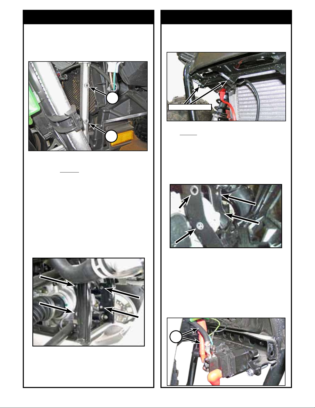
1. Locate the two holes (F) “shown below” above
the rear driver’s side A-arm. Mount your winch
contactor to this location using the supplied ¼”
x 1” bolts (6), two washers (8), and two ¼ nuts
(7) or using the supplied ¼” x 1.5” self-tapping
bolts (15) included. (NOTE: it is recommended to
mount the contactor so that the switch wires are
towards the middle of the ATV)
G
F
H
F
2. Slide the winch into the mount per orientation
shown in Figure 1. Mount your winch to the
Mount using the proper hardware supplied with
your winch. Don’t forget to route your winch
cable through your fairlead and attach your hook.
If your winch leads come close to hitting some-
thing, a lot of winches can also have the leads ro-
tated if needed (check with your winch provider).
3. Mount the entire winch assembly (winch, mount,
contactor, and fairlead) into location and assem-
ble using the included 8MM hardware. Shown in
image below.
LIGHT POD
E
D
4. Connect Rocker Switch wires to the contactor.
For REAR battery ATV’s you have two
options:
Route the BLACK and GREEN wires all the
way back to the rear mounted contactor and
connect the wires.
Locate the BLACK and GREEN wire ends with
a white plastic connector (D) and (G) located
back by the contactor. Cut these connectors off
and wire in using correct electrical connections.
Note: Under the front rack there is a orange and white
accessory wire that you can tap your switch into.
5. For REAR battery ATV’s, under the seat,
locate the BLUE and YELLOW wires (H)
in or near the battery Compartment. Connect
the Blue and Yellow wires to the contactor.
(Please refer to your winch’s wiring diagram)
Next locate the YELLOW and BLUE wires
(E) in the front of the ATV. Cut the zip ties
that hold the wires in place, route the wires to
the location of the winch leads. Remove the
Red protective coverings from the wire ends
and connect the cable to the appropriate lead
on the winch (please refer to your winch’s
wiring diagram). Finally use the shorter wires
(usually Red and Black) from your winch
package and connect the contactor to your
battery. (Please refer to your winch’s wiring
diagram)
POSITION 3
©2021 Copyright Kappers Fabricating, Inc. All rights reserved Page 5
1. Mount your Contactor to the ATV frame just above
winch mount location. “Shown below” using the
supplied two ¼” x 1.5” self- tapping bolts (15) or the
hardware included with your winch.
POSITION 5
Contactor location
J
J
POSITION 4
1. Locate the two holes (J) “shown below” by your
radiator on the passenger side. Mount your
winch contactor to this location, using the two
supplied ¼” x 1.5” self- tapping bolts (15).
2. Slide the winch into the mount per orientation
shown in Figure 1. Mount your winch to the
Mount using the proper hardware supplied with
your winch. Don’t forget to route your winch
cable through your fairlead and attach your
hook. If your winch leads come close to hitting
something, a lot of winches can also have the
leads rotated if needed (check with your winch
provider).
3. Mount the entire winch assembly (winch,
mount, contactor, and fairlead) into location and
assemble using the included 8MM hardware.
Shown in image below.
4. Wire the winch up per the instructions that
came with your winch.
Note: Under the front rack there is a orange and white
accessory wire that you can tap your switch into.
2. Slide the winch into the mount per orientation shown
in Figure 1. Mount your winch to the Mount using
the proper hardware supplied with your winch. Don’t
forget to route your winch cable through your fairlead
and attach your hook. Your may need to rotate your
winch leads if they come close to hitting something
3. Mount the entire winch assembly (winch, mount,
contactor, and fairlead) into location and assemble
using the included 8MM hardware. Seen below.
K
4. Wire the winch up per the instructions that came
with your winch.
5. Note: If your machine comes with pre ran battery
wires (K) you can use these wires instead if the wires
that came with your winch. Wire your contactor
to your winch using the shortest wires included
with your winch. (Do not forget to connect pre ran
battery wire to the battery.) Under the front rack
there is a orange and white accessory wire that you
can tap your switch into.

This manual suits for next models

1

Other KFI Automobile Accessories manuals

KFI OPEN TRAIL User manual

KFI

KFI OPEN TRAIL User manual

KFI 101215 User manual

KFI

KFI 101215 User manual

KFI OPEN TRAIL 105000 User manual

KFI

KFI OPEN TRAIL 105000 User manual

KFI 100700 User manual

KFI

KFI 100700 User manual

KFI A3000 Manual

KFI

KFI A3000 Manual

KFI 101355 User manual

KFI

KFI 101355 User manual

KFI 105250 User manual

KFI

KFI 105250 User manual

KFI UTV-DRS-K User manual

KFI

KFI UTV-DRS-K User manual

Popular Automobile Accessories manuals by other brands

VVDI MB TOOL user manual

VVDI

VVDI MB TOOL user manual

BURY POWERMOUNT Series operating manual

BURY

BURY POWERMOUNT Series operating manual

Thule 1235 instructions

Thule

Thule 1235 instructions

ASA Electronics Voyager VCCS150 quick start guide

ASA Electronics

ASA Electronics Voyager VCCS150 quick start guide

ANATEL S57L0 operation instruction

ANATEL

ANATEL S57L0 operation instruction

Thule 1265 instructions

Thule

Thule 1265 instructions

Vision X Cannon CTL-CPZ6 Series installation instructions

Vision X

Vision X Cannon CTL-CPZ6 Series installation instructions

Brodit ProClip 853044 quick start guide

Brodit

Brodit ProClip 853044 quick start guide

Directed DS3+ installation guide

Directed

Directed DS3+ installation guide

Truma Mover XT operating instructions

Truma

Truma Mover XT operating instructions

Funkwerk Bluetooth QD ID B013281 operating manual

Funkwerk

Funkwerk Bluetooth QD ID B013281 operating manual

Cruz 923-05x Assembly instructions

Cruz

Cruz 923-05x Assembly instructions

Warn 90030 installation instructions

Warn

Warn 90030 installation instructions

Haicom HI-701 BT user manual

Haicom

Haicom HI-701 BT user manual

bosal 024121 FITTING INSTRUCTION

bosal

bosal 024121 FITTING INSTRUCTION

DEFA 423866 Fitting instructions

DEFA

DEFA 423866 Fitting instructions

DoubleTake MAX 5 manual

DoubleTake

DoubleTake MAX 5 manual

Soundoff Signal nFORCE NEXUS Interior LED Lightbar quick start guide

Soundoff Signal

Soundoff Signal nFORCE NEXUS Interior LED Lightbar quick start guide

manuals.online logo
manuals.online logoBrands
  • About & Mission
  • Contact us
  • Privacy Policy
  • Terms and Conditions

Copyright 2025 Manuals.Online. All Rights Reserved.