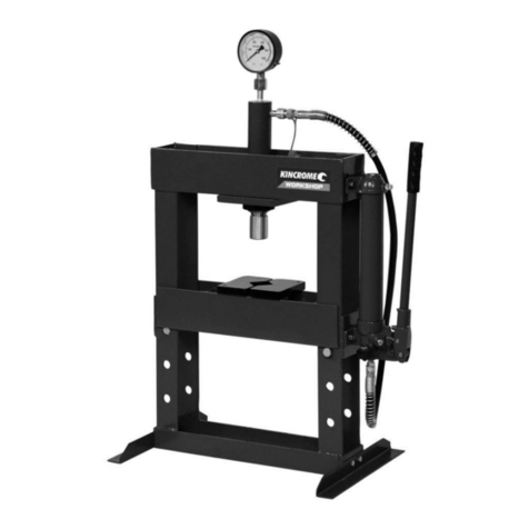
OPERATING HYDRAULIC BODY REPAIR KIT
Preparing Work Area
Before using the body repair kit, it is important to prepare work area properly. Follow this procedure each time
the repair kit is used to help prevent property damage and or serious injury.
1.) Thoroughly inspect body repair kit for damage or wear before each use. Briefly test operation of unloaded
hydraulic ram before using to work on any job. If ram is damaged or is malfunctioning DO NOT USE until
the problem is corrected.
2.) Consult owner’s manual for safety precautions correct use and recommended procedures before using
the body repair kit. The working load limit of the hydraulic ram is 10000 kg. NEVER EXCEED
WORKING LOAD LIMIT OF HYDRAULIC RAM. Utilisation of multiple connections also reduces the
working capacity of the tool.
3.) Clear children and others from work area before using the body repair kit. Another adult should be
nearby for extra safety and assistance but must be clear of repair area as it is used.
4.) Never use to compress or bend objects that are not securely attached and could be ejected from their
position. Do not apply force to objects that could shatter.
5.) Clear obstructions from work area. Working in tight or cluttered work areas is dangerous.
6.) Ensure Body repair kit and operator are on solid, level ground such as paved or concrete driveway or
garage floor. Uneven or sloped surfaces create hazardous working conditions and may dangerously
impede the function of the body repair kit.
Using the Body repair kit
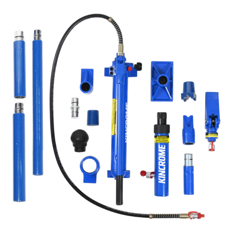
This hydraulic body repair kit comes with 14 accessory parts to allow for wide variety of applications. The
body repair kit is designed to repair and push automotive panels and assemblies.
1.) Place the body repair kit pump on a smooth surface.
2.) Select the correct part for the job to be done. The wrong accessory will create a potentially dangerous
situation.
i. The extensions 02-01, 02-02, 02-03, 02-04, use to achieve desired length, Caution the
longer the reach the lower the capacity.
ii. The base 03 normally used on the fixed end to spread the force
iii. Ram toe 04 and 05 attached to the ram to apply force where the ram head won’t fit directly in
the available space.
iv. Wedge head 06 suitable for creating gaps, applying high force to specific area
v. Cleft Cap 07 used to spread the force on curved surfaces
vi. Male connector 08 for attaching female end of the ram to a base tool
vii. Serrated cap 09 used on pushing end to prevent slip
viii. Rubber head 10 used to push out dents with minimal damage to the panel surface
