4
4T & 10T HYDRAULIC BODY REPAIR KITS
50FAN
Personal Safety
1. Stay alert. Watch what you are doing and use common sense when operating the tool. Do not use the tool while tired or
under the influence of drugs, alcohol, or medication. A moment of inattention while operating the tool increases the risk
of injury to persons.
2. Dress properly. Do not wear loose clothing or jewellery. Contain long hair. Keep hair, clothing and gloves away from
moving parts. Loose clothes, jewellery, or long hair increases the risk of injury to persons as a result of being caught
in moving parts.
3. Do not overreach. Keep proper footing and balance at all times. Proper footing and balance enables better control of the
tool in unexpected situations.
4. Use safety equipment. A dust mask, non-skid safety shoes and a hard hat must be used for the applicable conditions.
5. Always wear eye protection. Wear ANSI-approved safety goggles.
6. Have a qualified person maintain the equipment in good condition. Keep it clean for best and safest performance.
7. If the equipment needs repairing and/or there are parts that need to be replaced, have it repaired by authorized
technicians. Only use the replacement parts supplied by the manufacturer.
Unpacking
When unpacking the Body Repair Kit carefully inspect each component for damage that may have occurred during transit.
1. Check for any missing or damaged components and report these to the supplier for instructions.
2. Ensure all packaging materials are disposed of as per your local council guide lines.
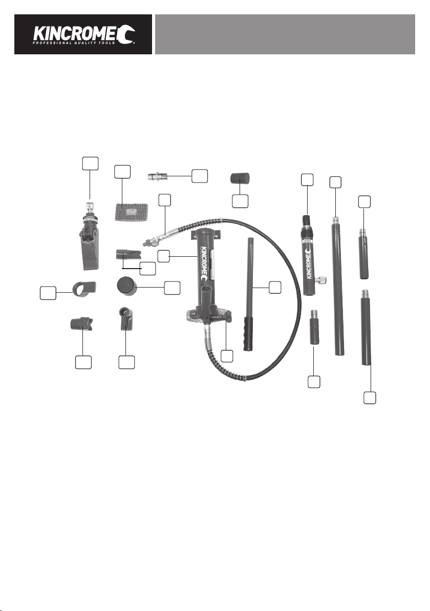
Understanding Your Product
There are several different attachments which are provided, which are to be used with the Hydraulic Body Repair Kits, depending
on the damage and the location of the vehicles damage.
a. Flat Base (16): is to be used to spread the load of the Hydraulic Ram. It should be connect to the female end of the
hydraulic ram (4), using the male connector (17).
b. Combination Head (11): is used to allign the pushing/pulling force of the hydraulic ram, when bearing against angled
frames. This accessory can be attached directly to the ram, or to extension tubes.
c. Rubber Head (13) : Is generally used to pop out dents from sheet metal, such as vehicle doors and body panels.
This accessory can be attached directly to the ram, or to extension tubes.
d. Wedge Head (14): is used to repair small dents in areas which are hard to reach and on angles.
This accessory can be attached directly to the ram, or to extension tubes.
e. Male Connector (17): Plugs into the female end of the Ram (4).
This accessory can be attached directly to the ram, or to the extension tubes.
f. Ram Toe & Plunger Toe (10 & 12): are generally used to push/pull the vehicles chassis.
This accessory can be attached directly to the ram, to the extension tubes or used in place of the flat plate when
space is limited.
g. Serrated Cap (18): is generally used for pushing during vehicle frame repairs.
This accessory can be attached directly to the ram, or to the extension tubes.
h. Extension Tubes (5, 6, 7 & 8): plug into one another for additionional combinations to reach the desired length.
i. Spreader (15): is to be used in restricted saces, when the Ram (4) can’t fit.
This accessory must be attached directly to the hose (3) of the hydraulic pump unit (1).