KIOUR VD1T User manual

1
COOLING –HEATING CONTROLLER Model VD1T
ATTENTION Firmware V3
Read carefully these instructions before installing and using this device and keep them for future reference. Attention to installation and electrical wiring. Use this device
only as described in this document and never use itself as a security device. The device must be disposed of in accordance with local standards for the collection of
electrical and electronic equipment.
DESCRIPTION
VD1T is a temperature controller for cooling –heating applications as well as food drying applications (eg sausages). The room temperature is controlled with an NTC /
PTC sensor. The evaporator sensor input through parameters can adjusted act as a door switch to control the room door. It has an automatic conventional defrost or
smart defrost function for energy saving and better control of the defrost process. It has 3 indication digits of temperature display with an accuracy of 0.5 ° C and 4
buttons. It has a relay 16A 250VAC that through parameters adjusted in operation: cooling or heating or heating with countdown. It has a buzzer that activates in case of
alarm. The device is mounted on a panel hole 29x71mm and it is restrained with plastic side brackets. Through the serial input it can be connected to a network either
through Cloud IoT on the CORTEX platform, or through a local computer in the CAMIN program for complete local recording and monitoring of the device.
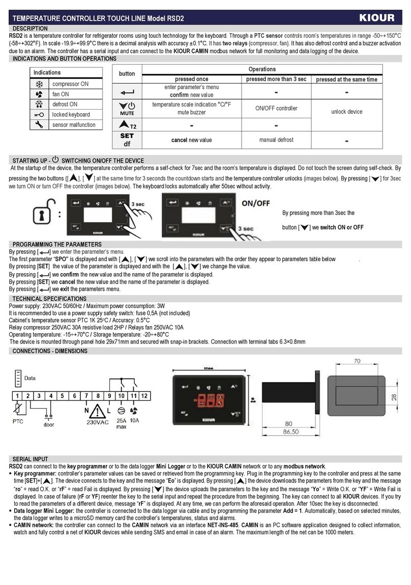
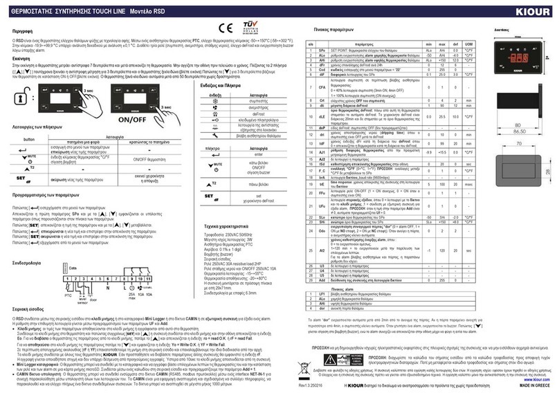
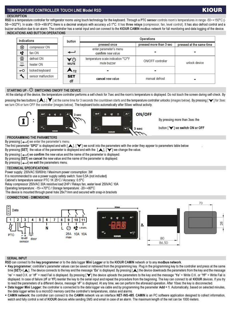
INDICATIONS AND BUTTONS FUNCTION
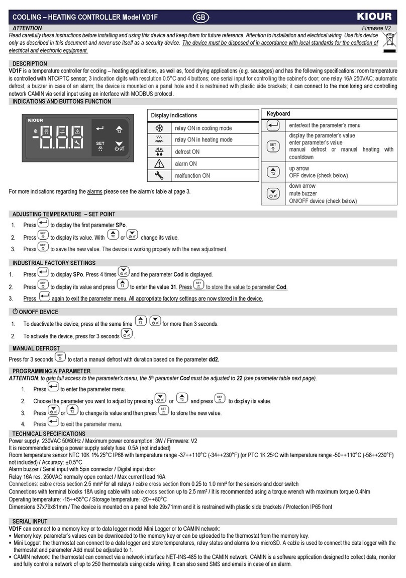
Display indications
relay ON in cooling mode
relay ON in heating mode
defrost ON
alarm ΟΝ
malfunction ON
Keyboard
enter/exit the parameter’s menu
display the parameter’s value
enter parameter’s value
manual defrost or manual heating with
countdown
up arrow
down arrow
ON/OFF device (check below)
For more indications regarding the alarms please see the alarm’s table at page 3.
1. Press to display the first parameter SPo.
2. Press to display its value. With or change SPo value.
3. Press to save the new value. The device is working properly with the new adjustment.
1. Press to display SPo. By pressing the parameter Cod is displayed.
2. Press to display its value and press
to enter the value 31. Press to store the value to parameter Cod.
3. Press again to exit the parameter menu, ‘YES’ is displayed on the screen. All appropriate factory settings are now stored in the device.
To activate or deactivate the device, press for 3 seconds .
Press for 3 seconds to start a manual defrost with duration based on the parameter dd2. This function also applies in case we have activated the smart defrost.
PROGRAMMING A PARAMETER
ATTENTION: to gain full access to the parameter’s menu, the 2nd parameter Cod must be adjusted to 22 (see parameter table next page)
1. Press to enter the parameter menu.
2. Choose the parameter you want to adjust by pressing or and press to display its value.
3. Press or to change its value and then press to store the new value.
4. Press to exit the parameter menu.
Power supply: 230VAC 50/60Hz / Maximum power consumption: 3W / Firmware : V3
It is recommended using a power supply safety fuse: 0.5Α(not included)
Room temperature sensor, terminals 5-6, NTC 10K 1% 25° C temperature range -37 ÷ + 110 ° C (-34 ÷ + 230 ° F) IP68 (or PTC 1K 25° C temperature range -50 ÷ + 110 °
C (-58 ÷ + 230 ° F) not included) / Accuracy: 0.5 ° C
Digital door input or input for evaporator temperature sensor, terminals 4-5, NTC 10K 1% 25° C temperature range -37 ÷ + 110 ° C (-34 ÷ + 230 ° F) IP68 (or PTC 1K 25° C
temperature range -50 ÷ + 110 ° C (-58 ÷ + 230 ° F) not included) / Accuracy: 0.5 ° C
Serial input 5pin connector
Relay 16Αres. 250VAC normally open contact / Max current load 16Α
Connections: cable cross section 2.5 mm² for all relays / cable cross section from 0.25 to 1.0 mm² for the sensors and door switch
Connections with terminal blocks 18A using cable with cable cross section up to 2.5 mm²/ It is recommended using a torque wrench with maximum torque 0.4Nm
Operating temperature: -15÷+55°C / Storage temperature: -20÷+80°C
Dimensions 70x35x28mm / The device is mounted on a panel hole 29x71mm and it is restrained with plastic side brackets / Protection IP65 front
ADJUSTING TEMPERATURE –SET POINT
INDUSTRIAL FACTORY SETTINGS
ON/OFF DEVICE
MANUAL DEFROST
TECHNICAL SPECIFICATIONS

2
VD1T connects via serial input to the cloud and the online CORTEX platform or to a local computer with the CAMIN program or to the memory key or to the Mini Logger or to
any Modbus network.
CAMIN program: local connection and monitoring - recording and management of the thermostat through the CAMIN program installed on a local computer.
Mini Logger recorder: The thermostat can be connected to the recorder and record based on selected minutes on a microSD memory card, its temperatures and the
state of the relays and alarms. It is connected via a cable to the serial input and we program the parameter Add = 1.
Memory key: the parameter values are stored in the memory key or recorded by it in the thermostat.
When the parameter rHC = 2, the relay operates in heating mode based on the parameter Hod while “SET”is displayed. By pressing the relay is activated and the
indication “rUn” is displayed. By pressing we see successively the temperature of the second sensor, if it is activated, as well as the remaining time. When time elapses,
the relay is deactivated and “End” is displayed on screen. By pressing again, the procedure starts over. The thermostat constantly controls the relay based on the adjusted
Set Point (SPo). If SPo changes during “rUn”, automatically the control of the relay is adjusted. If timer “Hod”changes during “rUn”mode, it will not change until the next
running cycle.
SMART DEFROST
Smart defrost function: The thermostat finds the ideal operating temperature of the evaporator and if the evaporator operates at a temperature lower than the ideal temperature
constant dSt than the ideal, and for a time longer than the time constant dS1, defrost begins.
Smart defrosting works in parallel and independently of conventional defrosting. It is automatic and the thermostat decides when to defrost and for how long. It is necessary
to connect the evaporator sensor and set the parameter 8, SOI = 0. The two types of defrosts - smart and conventional - can operate simultaneously based on the respective
settings. By enabling smart defrosting, the conventional defrost can be set to operate safely - for example one defrost every 48 hours. This time is renewed each time an
automatic defrost is performed.
Activate the smart defrost from parameter 24, dSE = 1. It is recommended to start the refrigerator, to make a defrost cycle, where it is activated with parameter 25, dSb = 1.
The time constants dS1 and temperature dSt are formed based on the image of the element: if we observe ice, we reduce the constants.
ELECTRICAL DIAGRAM - DIMENSIONS
ATTENTION: according to safety standards, the device must be properly positioned and protected from any contact with electrical parts. The device must be fastened in such a way that it
cannot be removed without the use of tools. Disconnect the main safety switch of the installation before proceeding to any maintenance. Disconnect the power supply of the device before
proceeding to any maintenance. Do not place the device near heat sources, equipment containing strong magnets, in areas affected by direct sunlight or rain. Prevent electrostatic discharges
and sharp objects from been inserted to the device. Separate signal cables from power supply cables to prevent electromagnetic disorders. Signal cables must never be in the same pipe with
the power supply cables. ATTENTION: Read carefully the technical specifications and make sure that the working conditions are appropriate. According to safety standards, the device must
be fastened in such a way that it cannot be removed without the use of tools
Dimensions are in mm. The device is mounted on panel hole with cut 29x71mm and restrained with plastic side brackets
Parameter SOI = 1: door switch or
SOI = 0: evaporator sensor terminals 4-5
PARAMETER TABLE
#
description
min
max
VD1T
Μ.Μ
1
SΡo
SET POINT: room temperature setting
LSP
HSP
2.0
°C/°F
2
Cod
Password in the following parameters Cod = 22
0
255
0
-
ANALOG INPUTS - TEMPERATURE
3
diF
Differential of room temperature SPo (thermostat delay)
0.1
25.0
3.0
°C/°F
4
LSP
Lower setting limit of SPo
-50.0
HSP
-2.0
°C/°F
5
HSP
Maximum setting limit of SPo
LSP
+110
8.0
°C/°F
6
dEC
Temperature indication as integer or decimal, where 0 = integer / 1 = decimal
0
1
1=decimal
-
7
Sen
Sensor type NTC/PTC
0 = PTC / 1 = NTC
0
1
1=NTC
-
8
SOI
Set 2nd input as NTC / PTC evaporator sensor or door switch:
0 = evaporator sensor / 1 = door switch
Selecting one setting automatically turns off the alarms and features of the other setting.
0
1
1=door
-
9
SΕ1
Room sensor offset
-9.9
+15.5
0.0
°C/°F
10
SΕ2
Evaporator sensor offset
-9.9
+15.5
0.0
°C/°F
11
tdS
Delay in displaying the actual room temperature on the screen when the door is opened
0
60
0
min
12
C_F
Temperature measurement unit: toggling between °C/°F do not adjust the SPo automatically, it must be
changed by the user :
0 = °C / 1 = °F
0
1
0=°C
°C/°F
ALARMS
13
ΑLo
lower alarm limit temperature of the cabinet
-50.0
+110
-4.0
°C/°F
14
ΑHi
higher alarm limit temperature of the cabinet
-50.0
+110
+15.0
°C/°F
15
At2
Time delay in activating “AΗi”, “ΑLo” and the buzzer among them.
This setting does not apply to sensor failure “LF1”, “LF2” and door alarm “dor”.
0
99
20
min
DIGITAL INPUT –DOOR SWITCH
16
dLd
Door switch operation
0 = OFF / 1 = NC (normally close contact) / 2 = NO (normally open contact)
In heating mode the door control is deactivated
0
2
0=OFF
-
SERIAL INPUT
FOOD DRYING APPLICATIONS (e.g. SAUSAGES) - HEATING MODE WITH COUNTDOWN

3
17
tdo
Time delay in deactivating the compressor once the door opens and activate the door alarm. Once the door
closes, the compressor is activated and the alarm turns off.
0
99
0
min
DEFROST
18
dFr
Time between two successive defrost, where if dFr = 0 or the relay is in heating mode, defrost is
deactivated.
0
50
6
hours
19
dd2
Defrost duration (manual and automatic)
1
90
18
min
20
dE5
Defrost end temperature - room temperature - terminals sensor 5-6
The defrost shut-off temperature is the temperature of the room, regardless of whether we have connected
the heat exchanger sensor. Above this room temperature the automatic defrost stops.
Manual defrosting starts regardless of the room temperature and is of duration dd2.
In case of fault (LF1) of the room sensor, the end of defrost temperature is not checked and is completed
after the selected time dd2.
0
25.0
10.0
°C/°F
21
dY4
Display indication during defrost
0 = room temperature is displayed
1 to 40 minutes = “dFr” is displayed from 1 to 40 minutes from the initiation of defrost
0
99
20
min
22
dP3
Dripping time, where the compressor is OFF after defrost
0
10
0
min
23
tdH
Time delay in activating high temperature alarm "AHi" after defrost.
The "AHi" alarm is not activated during defrost.
0
99
0
min
SMART DEFROST (more details page 2)
24
dSE
Smart defrost function
0 = NO
1 = YES
0
1
0
-
25
dSb
Starts a defrost cycle at the start of the device
0 = NO
1 = YES
0
1
1
-
26
dS2
Minimum time between two consecutive smart defrosts
40
255
60
min
27
dS1
Time constants, the steadier the increase, the harder it is to start smart defrosting
1
20
3
min
28
dSt
Temperature constant, the higher the constant, the harder it is to start smart defrosting
0.5
3.0
1.0
°C/°F
COMPRESSOR
29
CP2
Compressor’s minimum time OFF
0
4
3
min
30
CF3
Compressor’s operation in case of room’s sensor malfunction LF1 and in cooling mode, the compressor
operates as follows:
0 = 40% ΟΝ compressor (3 minutes ΟΝ, 4 minutes OFF) / 1 = ΟΝ constantly the compressor.
In heating mode with parallel sensor malfunction (LF1), the relay switches off.
0
1
0
-
RELAY
31
rHC
Relay operation mode, where 0 = cooling / 1 = heating / 2 = heating with countdown based on timer Hod
0
2
0=cooling
-
32
Ηοd
Countdown timer when the relay is in heating mode with countdown, adjust also parameter rHC = 2
1
255
1
min
NETWORK - GENERAL SETTINGS
33
Add
Device address on network
0
255
1
-
34
trE
Response time of the device on network
5
100
40
msec
35
bAU
Baud rate: 2 = 9600
-
-
2=9600
-
36
Pro
Cabinet’s program (factory settings) is displayed – no access
-
-
1
-
37
tPE
Unique product number –no access
-
-
45
-
ALARM TABLE
1
LF1
Room sensor malfunction
2
LF2
Evaporator sensor malfunction
3
ΑLo
Low room temperature
4
ΑHi
High room temperature
5
dοr
Open door alarm
6
EEr
RAM error: re-enter the SPo (see Setting the device temperature - SET POINT previous page)
The alarms are automatically deactivated once the cause of the alarm disappears.
Made in Greece.
The device is under two year’s guarantee. The guarantee is valid only if the manual instructions have been applied. The control and service of the device must be done by an authorized technician.
The guarantee covers only the replacement or the service of the device. KIOUR PC implements a Quality Management System according to EN ISO 9001:2015 Standard with registration number
01013192. KIOUR preserves the right to adjust its products without further notice
392 Mesogeion Avenue Agia Paraskevi 153 41 Τ: 210 6533730 F: 210 6546331 [email protected] www.kiour.com
V1.0.151020
Table of contents
Other KIOUR Temperature Controllers manuals
Popular Temperature Controllers manuals by other brands

Temperature@lert
Temperature@lert TM-WIFI220 user guide

DEVI
DEVI Devilink RS installation manual

Siemens
Siemens SITRANS TS Series operating instructions

Resol
Resol DeltaSol A Manual for the specialised craftsman

Automationdirect.com
Automationdirect.com SOLO SLM Series user manual

Tech Controllers
Tech Controllers EU-281 user manual