1.
INTRODUCTION
Thank you for purchasing the KISAE Ultimate Battery Charger. With our state of the art, easy to
use design, this product will offeryou reliable service by providing a multi-stage, multi-input battery
charger to charge the different types of batteries you have installed in either your home, boat, RV,
caravan, 4WD or commercial vehicle. This manual will explain how to use this unit safely and
effectively.
2.
PRODUCT DESCRIPTION
•Base unit (UC1240)
•Display Panel with Connection Cable
•IEC AC Input Cord
•Owner’s Manual
3.
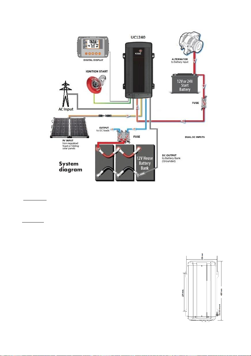
UNDERSTANDING THE UNIT
The charger is a fully automatic multi-stage, multi-input battery charger with the ability to charge
from utility AC, or an alternator linked to a battery, or via solar power with its built-in Maximum
Power Point Tracking (MPPT) Solar Controller. The house battery will be charged from utility AC
Input as priority. When Alternator and/or Solar inputs are also available, the house battery will also
be charged from either the Solar input or the Alternator input with various priority settings that
include the use of the ignition start pin on the vehicle. The charger prioritizes either alternator or
solar by performing custom setting and both functions are controlled from within the unit itself
without the need for external relays. See more details in the “House Battery Charging
Mechanism Setting” section on page 7.
During normal operation, the charger will do a full charge cycle on the House Battery Bank. User
may select GEL, AGM, Flooded, Lithium battery or Custom Programmable settings. Once the float
stage is reached, the charger transitions to a power supply mode to support any on-board DC
loads. The House Battery Bank will automatically restart a new charging cycle when the set point
for battery recharge is reached.
The unit provides a maximum of 80A charging current with the combination of 40A maximum
through the AC Charger and 40A maximum through the DC-to-DC Charger.
Multi-stage Charging Process for GEL, AGM and Flooded Battery Types
The charger is a fully automatic, set and forget charger. It is designed to recharge your deep cycle
batteries utilizing charger algorithms that help to maximize the life of your specialized deep cycle
batteries.
The charger features multi-stage smart charging technology that enables the charger to be
connected to your House Battery Bank permanently. With multiple input sources, you can be
assured of charging your batteries everywhere via the utility AC Input, the vehicle alternators, or
when the sun is shining on your solar array. Per battery manufacturer recommendations, deep
cycle batteries require a multi-stage charge sequence for perfect, fast, and accurate charging.
This charger delivers three primary charge stages:
Stage 1 –Bulk Charge: The battery is charged at full rated output current of the charger (as per the setting)
until the battery reaches its final charging voltage, known as its absorption voltage. In this step,
around 80% of the battery is recovered.
Stage 2 –Absorption Charge: With the charger voltage held steady, the remaining 20% of the battery is
replenished with the charger allowing the current to taper off as the battery approaches full charge.
Stage 3 –Float Charge: In the float stage the charger voltage is lowered and held at a constant and safe
predetermined level. This prevents the battery from being overcharged yet allows the charger to
supply enough current to make up for the self-discharge losses of the battery, and supports any
additional loads connected to the battery (such as DC lighting and refrigerators). This stage allows
the charger to be used as a DC power supply.
Stage 4 –Re-Charge: When the House Battery Bank voltage drops to below the set Recharge Voltage, the
charger will recharge the House Battery Bank again by switching to stage 1.
Multi-stage Charging Process for Lithium and Program Battery Types
The Battery Charger has a specific charging profile for Lithium batteries. It has its own charging
voltage and current settings that need to be set by the user. The charger delivers three primary
charge stages:
Stage 1 –Constant Current (CC mode): The battery is charged at the user selected maximum output charging