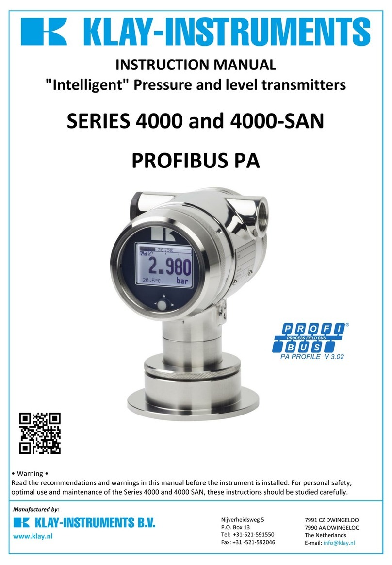
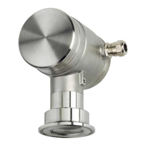
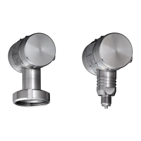
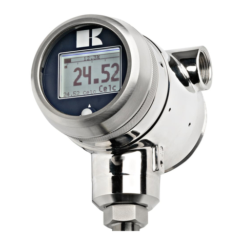
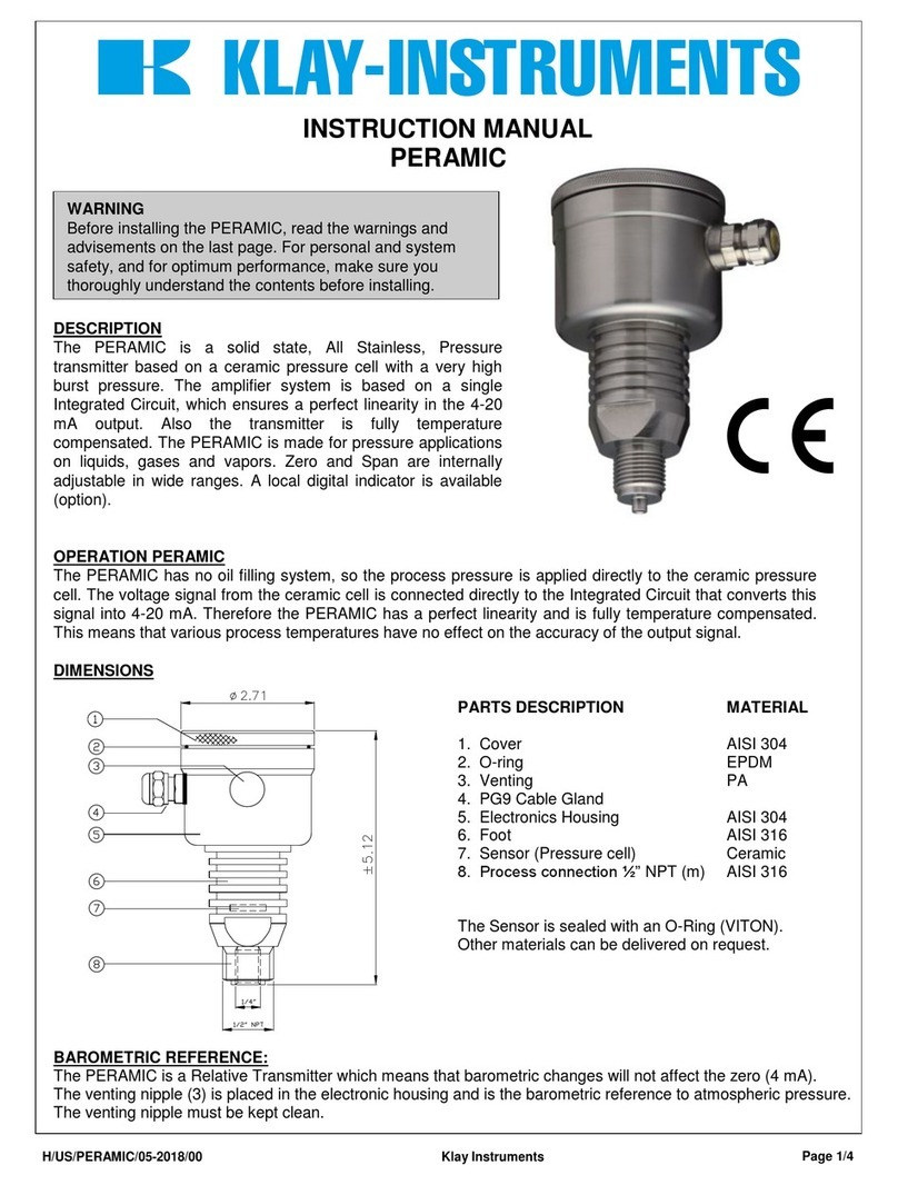
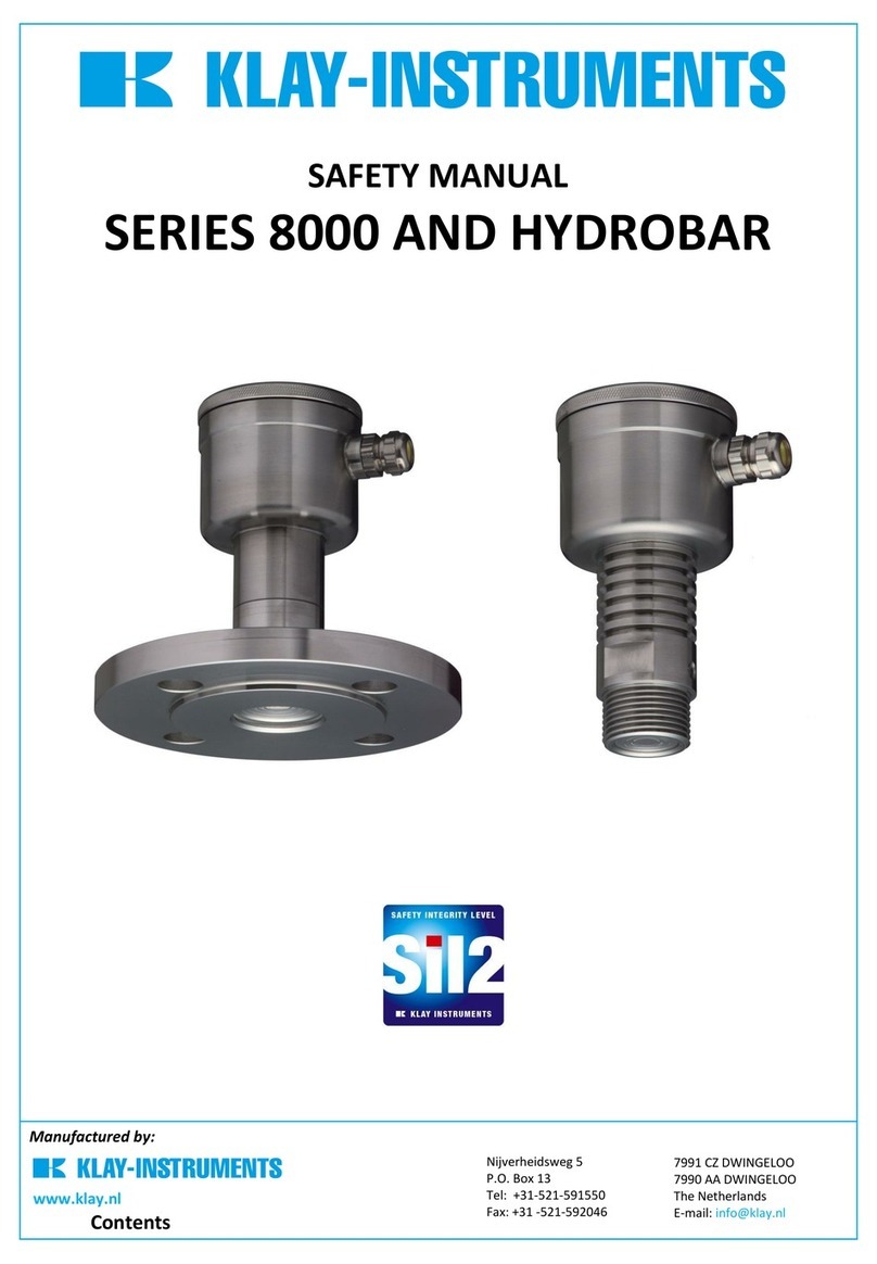
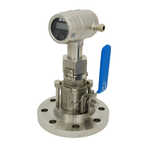
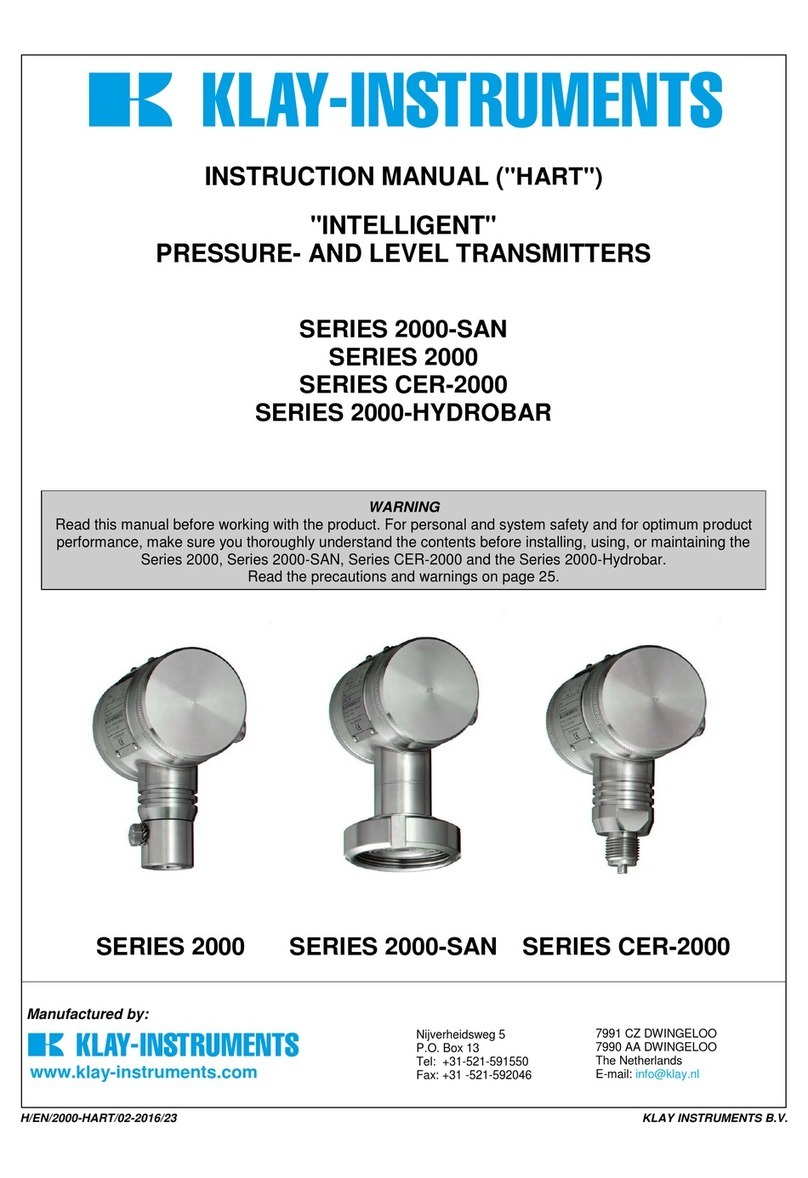
KLAY-INSTRUMENTS 2000-SAN Series User guide

Functional safety manual –Series 2000 and Hydrobar-I
SM-EN-2000/09-2013/01 Page 1
Contents
1. Functional Safety............................................................................................................................. 2
1.1 Scope ....................................................................................................................................... 2
1.2 Application area ...................................................................................................................... 2
1.3 Safety function ........................................................................................................................ 2
2. Compliance...................................................................................................................................... 3
2.1 Assumptions ............................................................................................................................ 3
2.2 Product identification.............................................................................................................. 3
2.3 SIL conformity.......................................................................................................................... 3
2.4 Relevant standards.................................................................................................................. 4
3. Safety............................................................................................................................................... 4
3.1 Safety requirements................................................................................................................ 4
3.2 Service Proven......................................................................................................................... 4
4. Safety-related characteristics......................................................................................................... 5
4.1 Basics ....................................................................................................................................... 5
4.2 Safe function............................................................................................................................ 5
4.3 Specific characteristics ............................................................................................................ 5
4.4 Time-dependent process of PFDavg.......................................................................................... 5
4.5 Service life ............................................................................................................................... 5

Functional safety manual –Series 2000 and Hydrobar-I
SM-EN-2000/09-2013/01 Page 2
1. Functional Safety
1.1 Scope
This safety manual applies to measuring systems consisting of Klay Instruments pressure transmitter
in a two wire 4-20 mA loop.
This functionally safety manual applies for:
Series 2000, 2000-SAN, CER-2000, 2000-SAN Cable, 2000-Hydrobar Cable and Hydrobar-I-Cable
The series 2000 with a serial number of the transmitter > 4309036
The Hydrobar-I with a serial number of the transmitter > 7309014
Software from Rev. V9.17
1.2 Application area
The measuring system can be used for process pressure or level measurement of gases, vapours and
liquids which meet the specific requirements of the safety technology.
1.3 Safety function
The device generates an analogue output signal of 4-20 mA that is proportional to the current pressure.
This is controlled by a micro processing unit and has to be distinguished between 4-20 mA. The fault
current is ≤3.9 mA or > 20.8 mA. Observe with the conception of the system, that the technical data of the
product-specific as well as Functional Safety Data Sheet may not be exceeded. Especially the permissible
operating condition (permissible temperatures, etc.) have to be ensured.
Make sure that the entire interconnection of different components fulfills the requirements
of the application. The operator is responsible for correct construction of the overall system.
After installation a validation of the safety function is required.
The damping of the output signal must be adapted to the process safety time.
The operability of the measuring device should be checked via proof test in regularly intervals. For
defining the scope and interval of tests, the following table can be used as a reference. However
each application has its own unique properties and exceptions. Klay Instruments is not an expert
in the customers process (technical field) and does not accept liability for consequential damage
of any kind due to use or misuse of the Series 2000 and Hydrobar I.
Industry
Application
Frequency of proof test
Twice a year
Yearly
Every two years
Food and Dairy
Fluids
●
Steam and Air
●
Homogenisors
●
Brewery and Beverage
Fluids
●
Steam and Air
●
Homogenisors
●
Pharmaceutical
Fluids
●
Steam and Air
●
Pulp and Paper
Fluids
●
Steam and Air
●
Industry
Application
Frequency of proof test
Twice a year
Yearly
Every two years
Shipbuilding and Marine
Fluids
●
Steam and Air
●
Water and Wasted Water
Fluids
●
Air
●
Chemical and Petrochemical
Fluids
●
Steam, Air and Gasses
●
Oil and Gas
Fluids
●
Steam, Air and Gasses
●
Drilling systems
●
Others (Machinebuilding)
Fluids
●
Steam, Air and Gasses
●

Functional safety manual –Series 2000 and Hydrobar-I
SM-EN-2000/09-2013/01 Page 3
The installation, maintenance and cleaning of the devices must be performed exclusively by
persons specifically trained and authorized for this purpose as far as they are familiar with
the devices!
Modifications on devices and connections void Functional Safety and the warranty!
It is the responsibility of the user to verify whether the chosen version of the device is
suitable for the intended application and the existing environmental conditions. Klay
Instruments does not assume any liability for an incorrect selection and its consequences.
2. Compliance
2.1 Assumptions
Failure rates are constant, wear of the mechanical parts is not taken into account.
The average ambient temperature during the operating time is 20°C - 40 °C (68 °C - 104 °F).
The environmental conditions correspond to an industrial environment.
The lifetime of the components is around 10 to 14 years (IEC 61508-2, 7.4.7.4, remark 3).
2.2 Product identification
Make sure the device has been ordered with SIL-conformity and has been delivered conformably.
The transmitter is clearly marked with a special SIL marking on the enclosure.
2.3 SIL conformity
The SIL conformity is confirmed by the verification documents in the appendix.
Series 2000 and Hydrobar I
IEC 61508:2010
Type B
FT0
SIL1
SC1
IEC 61511:2003
Type B
FT1
SIL2
Abbreviations, terms
SIL
Safety Integrity Level
HFT
Hardware Fault Tolerance
SFF
Safe Failure Fraction
PFDAVG
Average Probability of dangerous Failure on Demand
PFH
Probability of a dangerous Failure per Hour
FMEDA
Failure Mode, Effects and Diagnostics Analysis
λsd
Rate for safe detected failure
λsu
Rate for safe undetected failure
λdd
Rate for dangerous detected failure
λdu
Rate for dangerous undetected failure
DCS
Diagnostic Coverage of safe failures; DCS= λsd/(λsd+λsu)
DCD
Diagnostic Coverage of dangerous failures; DCD= λdd/(λdd+λdu)
FIT
Failure In Time (1 FIT = 1 failure/109h)
MTBF
Mean Time Between Failure
MTTF
Mean Time To Failure
MTTR
Mean Time To Repair
Further abbreviations and terms are stated in IEC 61508-4.

Functional safety manual –Series 2000 and Hydrobar-I
SM-EN-2000/09-2013/01 Page 4
2.4 Relevant standards
IEC 61508:2010
Functional safety of electrical/electronic/programmable electronic safety-related systems
IEC 61511-1:2003
Functional safety - safety instrumented systems for the process industry sector - Part 1:
Framework, definitions, system, hardware and software requirements
3. Safety
3.1 Safety requirements
Failure limit values for a safety function, depending on the SIL class (of IEC 61508-1, 7.6.2)
Safety integrity level
Low demand mode
SIL
PFDavg
4
≥ 10-5 … < 10-4
3
≥ 10-4 … < 10-3
2
≥ 10-3 … < 10-2
1
≥ 10-2 … < 10-1
Safety integrity of hardware for safety-related subsystems of type A (IEC 61508-2, 7.4.3)
Safe failure fraction
Hardware fault tolerance
SFB
HFT = 0
HFT = 1 (0)
HFT = 2
< 60 %
SIL1
SIL2
SIL3
60 % … < 90 %
SIL2
SIL3
SIL4
90 % … < 99 %
SIL3
SIL4
SIL4
≥ 99 %
SIL3
SIL4
SIL4
3.2 Service Proven
According to IEC 61511-1, paragraph 11.4.4, the failure tolerance HFT can be reduced by one for
service-proven subsystems if the following conditions are met:
The hardware of the device is selected on the basis of prior use (see IEC 61511-1 Cl. 11.5.3)
The device allows adjustment of process-related parameters only, for example, measuring
range, upscale or downscale failure direction.
The adjustment of the process-related parameters of the device is protected.
The function has a SIL requirement of less than 4.
SIL
Minimum hardware fault tolerance
(see 11.4.3 and 11.4.4)
1
0
2
1
3
2
4
Special requirements apply (see IEC 61508)
The user must have experience with process, and must be in compliance by the requirements of IEC
61511-1 clause 11.5.3. The operating experience must be recorded in the user’s list of equipment
approved for use in their facilities.

Functional safety manual –Series 2000 and Hydrobar-I
SM-EN-2000/09-2013/01 Page 5
4. Safety-related characteristics
4.1 Basics
The failure rates of the electronics, the mechanical parts of the transmitter as well as the process fitting
are determined by an FMEDA according to IEC 61508. The calculations are based on component failure
rates according to SN 29500. All values refer to an average ambient temperature during the operating
time of 55 °C (104 °F). For a higher average temperature of 60 °C (140 °F), the failure rates should be
multiplied by a factor of 2.5. A similar factor applies if frequent temperature fluctuations are expected.
4.2 Safe function
A measurement of absolute and relative pressure or level within the specified safety
accuracy of 0.1 % from full span.
The safety function response time is 100ms.
4.3 Specific characteristics
Failure Rate
Type of rating
Failure in time (FIT)
λsd (safe detected failure)
0.00
λsu (Safe undetected failure)
137.36
λdd (Dangerous detected failure)
2.35
λdu (Dangerous undetected failure)
45.37
Single channel architecture (1oo1D)
SIL
SIL2
HFT
0
Instrument type
B
SFF
75 %
PFDavg
TProof = 1 Year
TProof = 2 years
TProof = 5 years
TProof = 10 years
TProof = 15 years
< 0.202 x 10⁻³
< 0.401 x 10⁻³
< 0.997 x 10⁻³
< 0.199 x 10⁻²
< 0.298 x 10⁻²
4.4 Time-dependent process of PFDavg
The chronological sequence of PFDavg is nearly linear to the operating time over a period up to 10
years. The above values apply only to the TProof interval after which a recurring function test must
be carried out
4.5 Service life
After 10 to 14 years, the failure rates of the electronic components will increase, whereby the
derived PFD values will deteriorate (IEC 61508-2, 7.4.7.4, note 3).
Other manuals for 2000-SAN Series
2
This manual suits for next models
4
Table of contents
Other KLAY-INSTRUMENTS Transmitter manuals
KLAY-INSTRUMENTS
KLAY-INSTRUMENTS 2000-VALVE-RANGE Series User manual

KLAY-INSTRUMENTS
KLAY-INSTRUMENTS DP-4000 Series User manual

KLAY-INSTRUMENTS
KLAY-INSTRUMENTS TT4000 Series User manual

KLAY-INSTRUMENTS
KLAY-INSTRUMENTS 2000-SAN Series User manual

KLAY-INSTRUMENTS
KLAY-INSTRUMENTS DP-4000 Series User manual

KLAY-INSTRUMENTS
KLAY-INSTRUMENTS 2000-SAN Series User manual

KLAY-INSTRUMENTS
KLAY-INSTRUMENTS TT-2000 Series User manual
KLAY-INSTRUMENTS
KLAY-INSTRUMENTS 8000-SAN Series User manual

KLAY-INSTRUMENTS
KLAY-INSTRUMENTS PROFIBUS PA 4000 Series User manual

KLAY-INSTRUMENTS
KLAY-INSTRUMENTS 2000 Series User manual