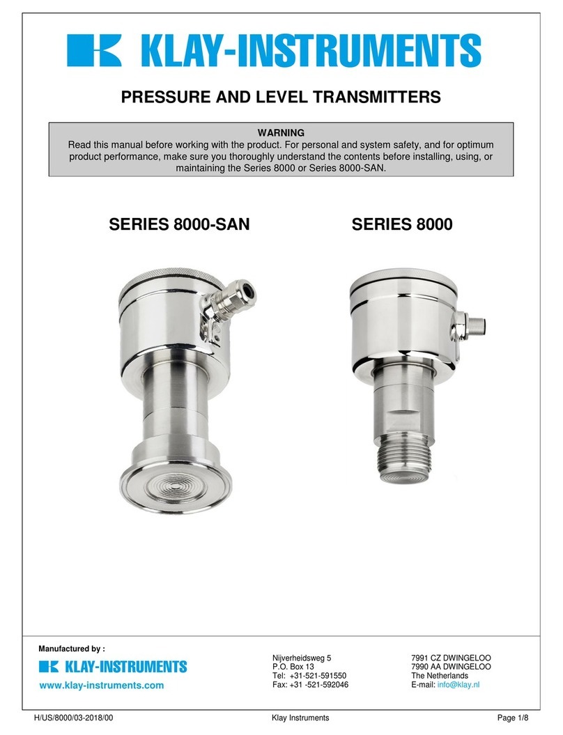
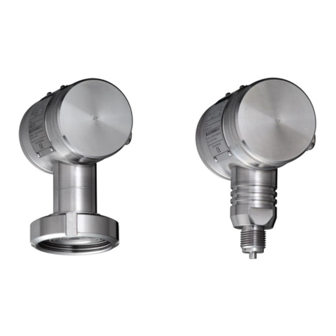
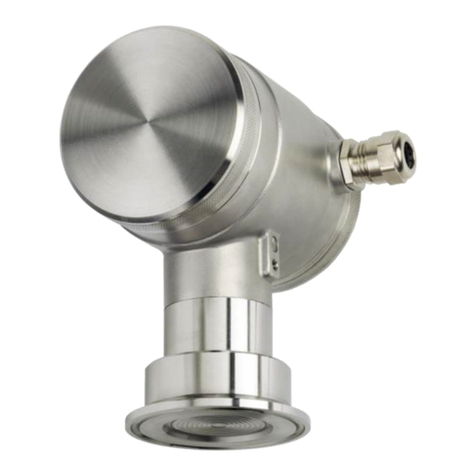
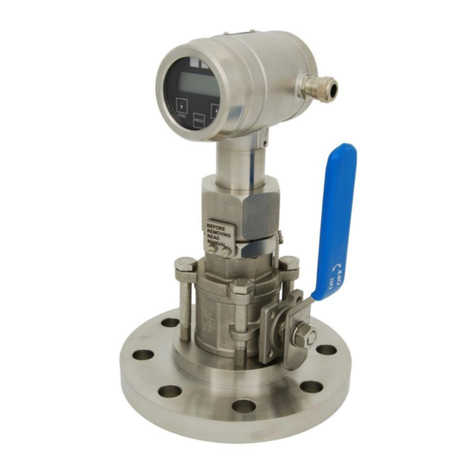
KLAY-INSTRUMENTS TT4000 Series User manual

EN-4000-TT-PROFIBUS-PA-09-2021-00 1
INSTRUCTION MANUAL
SERIES TT4000
PROFIBUS PA
"Intelligent" Temperature transmitter
• Warning •
Read the recommendations and warnings in this manual before the instrument is installed. For personal safety,
optimal use and maintenance of the temperature transmitters, these instructions should be studied carefully.
Nijverheidsweg 5 Tel: +31-521-591550
7990 AA Dwingeloo Internet: www.klay.nl
The Netherlands
KLAY-INSTRUMENTS B.V.

EN-4000-TT-PROFIBUS-PA-09-2021-00 2
CONTENTS
1. INTRODUCTION..................................................................................................................... 3
2. DIMENSIONAL DRAWINGS .................................................................................................... 4
3. INSTALLING THE TRANSMITTER ............................................................................................. 6
3.1 INSTALLING WELD-ON NIPPLE.....................................................................................................................6
3.2 CALIBRATION........................................................................................... Fout! Bladwijzer niet gedefinieerd.
3.3 PROFIBUS PA CABLE....................................................................................................................................6
3.4 WIRING.......................................................................................................................................................7
3.5 GROUNDING...............................................................................................................................................8
3.6 TERMINATION ............................................................................................................................................8
4. REMAINING .......................................................................................................................... 8
4.1 CE / EMC-RULES....................................................................................... Fout! Bladwijzer niet gedefinieerd.
4.2TRACEBILITY / YEAR OF MANUFACTURING .................................................................................................8
5. GRAPHIC DISPLAY AND NAVIGATION BUTTON....................................................................... 9
5.1GRAPHIC DISPLAY READOUT................................................................................................................... 100
5.2 SUMMARY PROGRAMMING POINTS.........................................................................................................10
6. EXPLANATION PROGRAMMING POINTS .............................................................................. 11
6.1 ZERO ADJUSTMENT (ZERO, 0%).................................................................................................................11
6.2 SPAN ADJUSTMENT (SPAN, 100%) ............................................................................................................ 11
6.3PA ADDRESS............................................................................................................................................ 122
6.4 DISPLAY SETTING OF UNITS..................................................................................................................... 122
6.5 OUTPUT SELECTION 0-100% or 100-0%.....................................................................................................12
6.6 DAMPING ADJUSTMENT ...........................................................................................................................13
6.7 LANGUAGE ...............................................................................................................................................13
6.8 DEVICE SETUP ...........................................................................................................................................13
6.9 READOUT............................................................................................... Fout! Bladwijzer niet gedefinieerd.6
6.10 INFORMATION....................................................................................... Fout! Bladwijzer niet gedefinieerd.6
6.11FACTORY................................................................................................................................................. 166
6.12FACTORY................................................................................................................................................. 166
7. PROFIBUS® PA .....................................................................Fout! Bladwijzer niet gedefinieerd.
7.1 PA INTERFACE.......................................................................................... Fout! Bladwijzer niet gedefinieerd.
7.2 IDENT NUMBER.........................................................................................................................................23
7.3 GSD FILES..................................................................................................................................................23
7.4 ENGINEERING UNITS................................................................................................................................. 24
7.5 PROFIBUS ADDRESS ..................................................................................................................................24
7.6 ROTATABLE DISPLAY.................................................................................................................................25
8. SPECIFICATIONS.................................................................................................................. 26
9. PRECAUTIONS AND WARNINGS ..........................................................................................277

EN-4000-TT-PROFIBUS-PA-09-2021-00 3
1. INTRODUCTION
The SERIES TT-4000 Profibus PA is a complete Stainless Steel temperature transmitter, based on a Pt100
element (⅓DIN Class B). The range of standard elements can be set from -20 until 200 and -40 until 400°C.
Other ranges are available on request. The Pt100 element is mounted in a stainless steel welding nipple
(sensor position 9). To obtain an accurate and fast measurement, the diameter of the insert must be as
small as possible. The resistance change of the Pt100 element due to temperature is converted into a
proportional 4-20 mA signal (2-wire).
Various process connections can be made including milk couplings (DN25, 40 and 50), Tri-clamp (1, 1 ½" or
2") and hygienic weld-on-nipples (¾ "BSP, Ø 28 mm). Thermowells are fully welded and manufactured from
bar stock. They are available in various designs and materials.

EN-4000-TT-PROFIBUS-PA-09-2021-00 4
2. DIMENSIONAL DRAWINGS
Series TT-4000
Description
Material
Description
Material
①
Cover
SS 304
⑧
Extended connection
SS 316
②
Display with navigation button
⑨
Process connection
SS 304
③
Cover with venting
SS 304
⑩
Insert
SS 316 L
④
Venting
PA
⑬
M20 x 1.5 cable entry (without gland) *
⑤
M20 x 1,5 cable entry (without gland) *
⑭
M20 x 1.5 cable entry (Blanking plug)
PE
⑥
O-Ring
EPDM
⑦
Electronic housing
SS 304
* As standard the Series 4000 will be supplied with two cable entries M20 x 1,5. A cable gland can be supplied by request
(extra costs).
Front view: Transparent cover, option “I” (extra price)

EN-4000-TT-PROFIBUS-PA-09-2021-00 5
Series TT-4000 - Remote
Description
Material
Description
Material
①
Cover
SS 304
⑧
Extended connection
SS 316
②
Display with navigation button
⑨
M12 Connector
SS 304
③
Cover with venting
SS 304
⑬
M20 x 1.5 cable entry (without gland) *
④
Venting
PA
⑭
M20 x 1.5 cable entry (Blanking plug)
⑤
M20 x 1,5 cable entry (without gland) *
⑥
O-Ring
EPDM
⑦
Electronic housing
SS 304
* As standard the Series 4000 will be supplied with two cable entries M20 x 1,5. A cable gland can be supplied by request
(extra costs).

EN-4000-TT-PROFIBUS-PA-09-2021-00 6
3. INSTALLING THE TRANSMITTER
The diaphragm of the transmitter is protected with a special protection cap. Protect the diaphragm
until installation takes place. Do not damage or bend the temperature sensor.
3.1 INSTALLING WELD-ON NIPPLE
A certified welder should perform the installation of the weld-on nipple.
Weld with Argon, MIG or TIG, with the smallest welding pin possible.
1. Cut a hole in the process vessel or pipe for a precise fit of the weld-on nipple. The hole
should be a tight fit when coupled with the weld-on nipple.
2. Prepare the hole by bevelling the edge to accept filler material.
3. Remove the weld-on nipple from the transmitter.
Remove the gasket and O-Ring out of the weld-on nipple!
WARNING
Improper installation may result in distortion of the weld-on
nipple. Excessive heat will distort the weld-on nipple. Weld in
sections as shown in the figure left. Allow adequate cooling
between passes. To reduce the chances of distortion to the
weld-on nipple, use a mandrel.
Determine (before welding) the position of the electronic
housing, so that the cable entry and the venting are in the right
position. After welding these positions are fixed.
4. Position the weld-on nipple in the vessel hole and tack six places. The weld sequence is
shown in the figure above.
5. Weld the weld-on nipple in place using 0,03 to 0,045 in. (0,762 to 1,143 mm) stainless rod as
filler material in the bevelled area. Adjust amperage for penetration.
6. Remove the mandrel after the welding operation.
3.2 CALIBRATION
All transmitters are fully calibrated at the factory, to customer specified range. If the calibration is
not specified, the transmitter will be calibrated at 0 –100 °C.
3.3 PROFIBUS PA CABLE
Under the cover ③you will find the terminal board. Special PROFIBUS® cable must be used for
proper communication. For further detailed description of cable selection, see "Guidelines for
planning and commissioning PROFIBUS DP/PA" and "PROFIBUS PA User and Installation Guideline"
both on www.profibus.com and IEC 61158-2 on www.iec.ch.
The PROFIBUS® standard defines two variations of bus cable: Type A and Type B. However it is
recommended to use cable Type A in all new installations. Type A is recommended for high
transmission speeds and permits a doubling of the network distance in comparison to Type B.
Shielded Profibus cable

EN-4000-TT-PROFIBUS-PA-09-2021-00 7
Type A Technical specification:
Impedance: 35 up to 165 Ohm at frequencies from 3 to 20 Mhz.
Cable capacity: < 30 pF per meter.
Core diameter: > 0,34 mm², corresponds to AWG 22.
Cable type: Twisted pair cable. 1x2 or 2x2 or 1x4 lines.
Resistance: < 110 Ohm per km.
Signal damping: max. 9 dB over total length of line section.
Shielding: CU shielding braid or shielding braid and shielding foil.
Max. Bus length: 200 m at 1500 kbit/s, up to 1,2 km at 93,75 kbit/s. (Extendable by repeaters)
Using other types of cable will result in incorrect and disrupted transmissions in the PROFIBUS®
network and is strongly discouraged. Do not run wiring in open trays with power wiring, or near
heavy electrical equipment (for example frequency controllers or heavy pumps). To eliminate
electromagnetic effects it is highly recommended to us a EMC Cable gland. (Option G73)
3.4 WIRING
Under the cover ③you will find the terminal board.
The figure above shows the wiring connection of the transmitter. The 2-wires must be connected to +
and - on the terminal board. The wiring terminals can be operated without a screwdriver. The
opening levers of the terminals can be lifted and pressed down by hand. Lift the opening levers of the
terminals and insert the corresponding wires. Press down the levers by hand, the terminal spring will
close and the wire is clamped. Optionally a secondary 4-20 mA output is available on request.
The transmitter is connected with standard two-wire shielded cable. Do not run signal wiring in open
trays with power wiring, or near heavy electrical equipment (e.g. Frequency controllers or heavy
pumps).
Reversing the polarity will not damage the transmitter, but the transmitter will not function until the
+and –are properly connected.
Insert the wires into the connector and
push the lever down by hand.
Illustrative side view

EN-4000-TT-PROFIBUS-PA-09-2021-00 8
3.5 GROUNDING
The transmitter must always be connected to ground. In case the process connection is already
connected to ground (e.g. by the tank or pipe line) do not connect the instrument to ground.
Please ensure that the instrument is not connected to ground twice to prevent an “Earth loop”.
3.6 TERMINATION
Termination of the bus prevents signal reflections on the PROFIBUS® cable. A terminator is a
combination of a resistor and a capacitor. Wrong or missing termination results in transmission
errors. At the end of each cable trunk a terminator must be used. In common a terminator is
integrated in a segment coupler. When there is no integrated terminator present in the trunk, a
separate terminator must be used.
4. REMAINING
4.1 / EMC-RULES
All Klay transmitters are manufactured in accordance with the RFI / EMC directives and comply with
the CE standard. All transmitters are fitted with RFI filters, which provide optimum, trouble-free
operation. Our products are in conformity with EMC-Directive 2014/30/EU based on test results
using harmonized standards.
4.2 TRACEBILITY / YEAR OF MANUFACTURING
The year of manufacturing of the transmitter can be traced as follows: take the first two numbers
from the serial number that is engraved in the transmitter and add 1970 to it.
Example: Serial Number 4302123. The year of manufacturing is 1970 + 43 = 2013.

EN-4000-TT-PROFIBUS-PA-09-2021-00 9
5. GRAPHIC DISPLAY AND NAVIGATION BUTTON
The Series 4000 has a multifunctional display where different values can be displayed simultaneously. The
display is equipped with a backlight. The entire menu is controlled by a navigation button. The navigation
button has the following possibilities of movement: up, down, left, and right. The navigation button needs
to be pushed when conformation or saving is needed.
Move the navigation button up or down to browse through various menus.
These movements can be distinct in choices of: program points, navigation
through menu’s and increase or decrease measurement value’s.
Move the navigation button left or right to navigate horizontally through the
menu or positions on the display.
It is always possible to return to the previous menu. Move the navigation
button to the left to return to the previous menu.
By pushing the navigation button each choice will be confirmed or a setting
will be saved.
Figure 1. Display Series TT-4000, fully rotatable (360 )

EN-4000-TT-PROFIBUS-PA-09-2021-00 10
5.1 GRAPHIC DISPLAY READOUT
When the transmitter is powered, a flash screen with the name of the transmitter (Series 4000) and
the software version appear for a few seconds. The PROFIBUS® address is shown at the bottom of
the display. As standard (Unconfigured) the address is 126. This address is used for configuration and
commissioning purposes only. The address can be changed with Program point P103 or a Profibus
Master device (Only Class 2).
EXPLANATION OF SYMBOLS:
1. –Linear output Straight line means no linearization is applied. When a linearization is applied a
curve will be displayed.
2. –Profibus PA: Profibus PA Protocol applied
3. –Write protection on/off: Displays if protection against adjustments and configuration is on or off
4. –Secondary Measurement:Displays a secondary chosen measurement.
5. –Bargraph 0 - 100 % from span:Displays the percentage of the measured span.
6. –Measurement: Displays the actual reading, temperature or percentage
7. –Unit:Displays the selected unit (a temperature transmitter will present °C).
8. –Absolute:Appears when the measurement is in absolute range.
5.2 SUMMARY PROGRAMMING POINTS
PROGRAM POINT
NAME
FUNCTION
P100
Menu-Exit menu
Start and exit
P101
ZERO value
Zero adjustment (ZERO 0%) with or without process temperature
P102
SPAN value
Span adjustment (SPAN 100%) with or without process temperature
P103
PA Adress
Selection of PA address 2 to 126 (factory setting 126)
P104
UNITS
Selection of engineering unit to be displayed
P105
REVERSE OUT
Output selection 0 –100% or 100 %-0%
P106
DAMPING
Adjustable damping (0,00 till 25,00 s)
P107
LANGUAGE
Language choice between: English, Espanol,Dutch, French,German,
Polish .
P108
DEVICE SETUP
Configuration of: Protection, Backlight, Read Temp Min/ Max,
Secondary value, PA_OUTSCALE
P109
READOUT
Readout options on display: unit, percentage and Ambient
Temperature
P110
INFORMATION
Contact information of Klay Instruments, made settings, and software
revision
P111
FACTORY
Only available for the manufacturer
P112
FACTORY
Only available for the manufacturer
Configuring the transmitter local and remote simultaneously will cause transmission errors and must be prevented.

EN-4000-TT-PROFIBUS-PA-09-2021-00 11
6. EXPLANATION PROGRAMMING POINTS
6.1 ZERO ADJUSTMENT (ZERO, 0%)
The transmitter is set to 0 °C at 0%.
The ZERO can be adjusted at a lower or higher point. This will be
explained step by step by an example.
Example: Increase ZERO till +10 °C.
1. The measuring unit of the transmitter is set to Celsius degrees. If not this can be selected by
choosing the right measuring unit in program point P104 –UNITS (paragraph 6.4)
2. Navigate to program point P101 - ZERO Value, and push the navigation button to enter the menu.
3. Two choices appear on the screen: “set manual” and “use process”
Set manual = Configuration without test temperature.
Use process = Configuration with process temperature.
4. Choose “Set manual”, +000.0 (°C) will appear on the display.
5. Increase this value with the navigation button to +10 °C, at the bottom of the screen the URV
is displayed and changes according to the adjusted zero. push to confirm, and select
to save the setting.
6. The transmitter will return to the home screen. The zero (0%) is adjusted to +10°C.
The menu zero adjustment also has the choice of “use process”. The transmitter can be adjusted to
zero in a real process situation. When chosen, the transmitter will measure the temperature in an
actual process. This measurement will be used as the zero value. (0% )
1. Navigate to program point P101, and push the button to enter the menu.
2. Choose “use process”, and push to confirm. The transmitter will display the actual measured
temperature.
3. Push the navigation button to confirm, and select to save the setting.
4. The transmitter will return to the main menu.
6.2 SPAN ADJUSTMENT (SPAN, 100%)
This setting can be used to adjust the range (SPAN) according to an
entered value or adjusted with or without an applied temperature.
The maximum temperature which can be measured (100%) is the measurement at
ZERO (P101) + the entered value SPAN (P102). If the ZERO (P101) is increased, then the
maximum measured value will automatically be set higher at same rate as the zero.
The following example will explained step by step.
1. Example: Measurement range +10 till +110 °C = 0 - 100%.
2. The span must be set at 100 °C.
3. The zero was set in the previous menu (P101) at +10°C.
4. Navigate to program point P102 - SPAN Value, and push the navigation button to enter the menu.
5. Two choices appear on the screen: Set manual and “Use process”
6. Choose Set manual, a value will appear on the screen.
7. Adjust the SPAN with the navigation button to +110 °C. and select to save the setting
8. The transmitter will return to the home screen.
The menu span adjustment also has the option of “use process”. The transmitter can be adjusted to
the span in a real process situation. When chosen, the transmitter will measure the temperature in
an actual process. This measurement will be used as the span value. (100%)
1. Navigate to program point P102, and push the button to enter the menu.
2. Choose “use process”, and push to confirm. The transmitter display the measured temperature.
P101
Zero Value
P102
Span Value

EN-4000-TT-PROFIBUS-PA-09-2021-00 12
3. Push the navigation button to confirm, and select to save the setting.
6.3 PA ADDRESS
In this menu a PA Address from 2 till 126 can be selected.
1. Navigate to program point P103 - PA Address and push the navigation button to enter the menu.
2. Select the address with the navigation button and push to confirm. Select to save the setting.
3. The following message appear on the display:
4. The transmitter will automatically restart
5. The changed address is displayed in the startup screen.
6.4 DISPLAY SETTING OF UNITS
Two engineering units can be displayed on the display.
Factory setting = °C (Celsius)
1. Navigate to program point P104 –UNIT, and push the navigation button to enter
the menu.
2. Several engineering units can be selected. Each selected engineering unit is automatically
converted to the correct value of the corresponding unit.
3. Navigate through this menu and choose the required unit, push to confirm.
4. The Save icon will be displayed to indicate that the setting is saved.
5. The transmitter will return to the main menu; the measured reading will be displayed in the
chosen unit in the home screen.
For correct conversion between both temperature scales the following conversion calculation must be used.
Celsius to Fahrenheit
°C = (°F −32) × 5⁄9
Fahrenheit to Celsius
°F = °C × 9⁄5+ 32
CAUTION: The selected temperature unit is only visible on the display, when UNITS is chosen in P109 –Readout.
6.5 OUTPUT SELECTION 0-100 % or 100 –0 %
The transmitter is standard set to 0-100%.
1. Navigate to program point P105 –Reverse output, and push the navigation
button to
enter the menu.
2. Two choices appear on the screen 0-100% and 100 –0 %
3. Make an output choice and push to confirm.
4. The Save icon will be displayed to indicate that the setting is saved.
5. The transmitter will return to the main menu.
The transmitter will
restart.
PA Address
P103
PA Address
P104
Units
P105
Reverse mA

EN-4000-TT-PROFIBUS-PA-09-2021-00 13
6.6 DAMPING ADJUSTMENT
The transmitter has an adjustable damping between 0,00 to 25,00
seconds. Factory setting = 0,00 seconds
1. Navigate to program point P106 –DAMPING, and push the navigation button to
enter the menu.
2. Two choices appear on the screen: Set and Reset
3. Make a choice and push to confirm.
Choosing Set allows a value to be set between 0,00 and 25,00 seconds.
Select Set, and push the button to confirm.
Adjust the damping with the navigation button, push to confirm.
The Save icon will be displayed to indicate that the setting is saved.
The transmitter will return to the main menu.
Choosing Reset will put the setting back to factory setting (0,0 seconds)
Select Reset, and push the button to confirm.
The Save icon will be displayed to indicate that the setting is saved, the setting
will be put back to factory setting 0,00 s.
The transmitter will return to the main menu.
6.7 LANGUAGE
In this menu the preferred menu language can be selected.
1. Navigate to program point P107 - LANGUAGE, and push the navigation button to
enter the menu.
2. Five choices appear on the screen: English, Español, Dutch, French, German, Polish.
3. Make a choice and push to confirm.
4. The Save icon will be displayed to indicate that the setting is saved.
5. The transmitter will return to the main menu.
6.8 DEVICE SETUP
In this menu, several operational settings can be made for the
transmitter.
1. Navigate to program point P108 –Device Setup, and push the navigation button
to enter the menu.
2. Eight choices appear on the screen: Protection - Alarm output - Backlight - Temp units –
Temp min/max –Sec. Value - Set Time and PA_OUT_SCALE.
3. Choose the desired option, push to confirm.
4. Below are the choices displayed. They can be selected and configured using the navigation
button.
Protection: Local: The local protection for adjusting settings locally on the
transmitter.
Backlight: Choice between: On, Sleep mode (Turn off backlight after 5 minutes)
and Off. The intensity of the backlight is depending on the output current.
Temp min/max: Two choices appear on the screen: Readout and Reset
By choosing Readout the last measured minimum and maximum temperature
values of process and ambient appear. For the process temperature, a new value
is stored in a change of temperature more than 2 ˚ C. For the ambient
P106
Damping
P107
Languages
P108
Device Setup

EN-4000-TT-PROFIBUS-PA-09-2021-00 14
temperature this is 5 C. By choosing Reset the previous stored values will be
deleted.
Sec. Value: Four choices appear on the screen for the secondary readout on the
main screen, Unit, Rate and Ambient Temperature.
PA_OUT_SCALE: On this menu scaling options for analog Inpu Block (profibus
Output) can be configurd locally on the transmitter. Two choices apperes on the
screen Set 1:1 an set Manuel
oWith option Set 1:1 a scaling can be set with the following menu choices:
EU100, EU0 and Unit. As standard the values are the same as the last saved
Zero, Span and engineering unit (P109 must be set to unit or percentage).
Select EU100 to enter a value for the 100% scaling point.
Select EU0 to enter a value for the 0% scaling point.
Select Unit to enter the engineering unit code.
oWith option Set manual the current scaling configuration (Profibus
output) is shown. Set manual should only be used for units not supported
by the Series 4000, or when a different scaling then the local readout is
needed on the Profibus output. The engineering units can be found in
the attachment of this manual or on www.klay.nl under section
downloads.
The engineering units can be found in the attachment of this manual or in the digital version on
www.klay.nl under section downloads.
Profibus scaling will be explained step by step by the following examples:
Scaling Example - Temperature:
Configure the Zero - P101 (If necessary)
Configure the Span - P102 (If necessary)
Select Celeciusr in program point P104 (or any other Temperature unit)
Select Unit in program point P109
Navigate to program point P108 and select PA OUT_SCALE
Configure the scale with Set 1:1, navigate to save, to save the setting.
The transmitter will restart to load the new scale.
Scaling Example - Percentage:
Configure the Zero - P101 (If necessary)
Configure the Span - P102 (If necessary)
Select Percentage in program point P109
Navigate to program point P108 and select PA OUT_SCALE
Configure the scale with Set 1:1, navigate to save, to save the setting.
The transmitter will restart to load the new scale.
Transducer Block
P101 (LRV)
P102 (URV)
P104 (Unit)
P109 (Readout)
Analog Input block
Set 1:1 (P108 - PA OUT_SCALE)
Adjustable scaling based on the stored
transducer block values
Set manual (P108 - PA OUT_SCALE)
Adjustable scaling only for not supported

EN-4000-TT-PROFIBUS-PA-09-2021-00 15
CAUTION: Do not change the Zero, Span, Unit or Readout (P109) after configuring the Profibus
Out scaling, as described above. Changing will result in invalid Profibus communication.
6.9 READOUT
In this menu, the readout on the display is determined. This is the type
of measurement appearing on the home screen. Factory Setting = Unit
1. Navigate to program point P109 –READOUT, and push the navigation button to
enter the menu.
2. Four choices appear on the screen:
Temperature Unit = Unit as chosen in P104
Percentage = 0-100%
Ambient Temperature = Ambient temperature (Temperature inside the
electronic housing)
3. Navigate to the desired choice, confirm the selection by pushing the navigation
button. The Save icon will be displayed to indicate that the setting is saved.
4. The transmitter will return to the main menu.
6.10 INFORMATION
This menu shows a collection of information from the
transmitter and contact information from the manufacturer.
1. Navigate to program point P110 - Information and push the button to confirm.
2. Push the navigation button up and down to see all of the information
3. Push the button to leave this menu.
Below is a representation of this information screen:
Klay Instruments
www.klay.nl
+31521591550
Version - Software revision
No: - Serial number transmitter
Zero - Zero
Span - Span
Damping - Damping (in seconds)
Output - Output 0- 100% or 100 –0 %
Local Prot - Protection On or Off
Sec. Value - Selected secondary configuration
Backlight - Backlight On, Sleep mode or Off
Temp - Temperature unit Celsius or Fahrenheit
Index 27 OUT (record)
Float, PV SCALE Engineering Units at 100% = 200.0
Float, PV SCALE Engineering Units at 0% = 0.0
Index 28 OUT_SCALE (record)
Float, Engineering units at 100% = 100.0
Float, Engineering units at 0% = 0.0
Unsigned16, Units Index = 1001
Unsigned8, Decimal Point = 1
Example Percentage: Analog input block Slot 1
P109
Readout
P110
Information

EN-4000-TT-PROFIBUS-PA-09-2021-00 16
PA version - Profibus version 3.02
6.11 FACTORY
Only available for the manufacturer.
6.12 FACTORY
Only available for the manufacturer.
P111
P112

EN-4000-TT-PROFIBUS-PA-09-2021-00 17
7. PROFIBUS® PA
7.1 PA INTERFACE
The Series 4000-PROFIBUS PA is developed as a PROFIBUS® Slave device. A slave device is a
addressable peripheral device which reads process information and delivers output information to
the Master device in the PROFIBUS® system. The Series 4000 is developed for Profibus PA Profile
V3.02 and is backwards compatible with Profile version V3.01.
The Series 4000 supports 2 communication layers:
●
DP-V0:
Cyclic exchange of process data and exchanging diagnosis functions between
master and slaves.
●
DP-V1:
Acyclic data exchange and alarm handling between master and slaves for diagnosis,
control, monitoring and alarm handling of the slaves in parallel with cyclic data traffic.
The PROFIBUS® PA network is standardized using a block models. The different block types are
explained below.
Block Type
Description
Function Block
Control system behavior like for example: Analog Input,
Analog Output, Discrete Input, Discrete Output and
Totalizer.
Transducer Block
Converting mapping between process data and Function
Blocks. The Transducer Block is used to perform
preprocessing and calibration parameters of device data
according to specific device settings. At least one Transducer
Block has to be available for a PROFIBUS® PA field device.
Physical Block
Describes the specific data identifying the individual physical
device properties such as the device name, manufacturer,
and serial number.
Device
Parameters
Internal Device
Parameters
Transducer Block
Analog Input
Physical Block
Function Block Shell
Function Block Application
PROFIBUS PA Protocol Stack

EN-4000-TT-PROFIBUS-PA-09-2021-00 18
Physical Block Parameters (Slot 0)
In the table below the Physical Block parameters.
Index
Name
Type
Description
16
BLOCK_OBJECT
Record
Block object
Reserved
Unsigned8
0
Block_Object
Unsigned8
0x01, physical block
Parent_Class
Unsigned8
0x01, Transmitter
Class
Unsigned8
250, not used
Dev_Rev
Unsigned16
1
Dev_Rev_Comp
Unsigned16
1
DD_Revision
Unsigned16
0
Profile
OctetString(2)
MSB: 0x40 -> Number of the PROFIBUS PA profiles
within PI Profile Class 64
LSB: 0x02 -> Class B
Profile_Revision
Unsigned16
0x302: PA Prfile Revision 3.02
Execution_Time
Unsigned8
0
Number_of_Parameters
Unsigned16
29, number of parameters
Address_of_View_1
Unsigned16
0x00F8, View_1 has an index 248
Number_of_Views
Unsigned8
1, only one View_1 in Device
17
ST_REV
Unsigned16
ST_REV shall be incremented at least by one if at
least one static parameter in the corresponding
block has been modified
18
TAG_DESC
OctetString(32)
19
STRATEGY
Unsigned16
20
ALERT_KEY
Unsigned8
21
TARGET_MODE
Unsigned8
Target mode
22
MODE_BLK
Record
Actual_mode
Unsigned8
Actual mode
Permitted_mode
Unsigned8
Permitted mode
Normal_mode
Unsigned8
Normal mode
23
ALARM_SUM
Record
Current
OctetString(2)
Current alarm
Unacknowledged
OctetString(2)
Unacknowledged alarm
Unreported
OctetString(2)
Unreported alarm
Disabled
OctetString(2)
Disabled alarm
24
SOFTWARE_REVISION
VisibleString(16)
Revision-number of the software of the field device
25
HARDWARE_REVISION
VisibleString(16)
Revision-number of the hardware of the field device
26
DEVICE_MAN_ID
Unsigned16
Identification code of the manufacturer of the field
device
27
DEVICE_ID
VisibleString(16)
Manufacturer specific identification of the device
28
DEVICE_SER_NUM
VisibleString(16)
Serial number of the field device
29
DIAGNOSIS
OctetString(4)
Detailed information of the device, bitwize coded.
More than one message possible at once.
30
DIAGNOSIS_EXT
OctetString(6)
Additional manufacturer-specific information of the
device, bitwize coded. More than one message
possible at once.
31
DIAGNOSIS_MASK
OctetString(4)
Definition of supported DIAGNOSIS information-bits
(0: not supported, 1: supported)
32
DIAGNOSIS_MASK_EXT
OctetString(6)
Definition of supported DIAGNOSIS_EXTENSION
information-bits (0: not supported, 1: supported)
33
DEVICE_CERTIFICATION
VisibleString(32)
Certifications of the field device, e.g. EX certification

EN-4000-TT-PROFIBUS-PA-09-2021-00 19
34
WRITE_LOCKING
Unsigned16
Software write protection
35
FACTORY_RESET
Unsigned16
Parameter for the device resetting
36
DESCRIPTOR
OctetString(32)
37
DEVICE_MESSAGE
OctetString(32)
38
DEVICE_INSTAL_DATE
OctetString(16)
39
NULL_PARAM
Optional parameter LOCAL_OP_ENA isn't
implemented
40
IDENT_NUMBER_SELECT
41
NULL_PARAM
Optional parameter HW_WRITE_PROTECTION isn't
implemented
42
FEATURE
Record
Indicates optional features implemented in the
device and the status of these features which
indicates if the feature is supported or not
supported.
Supported
OctetString(4)
Supported features
Enabled
OctetString(4)
Enabled features
43
COND_STATUS_DIAG
Unsigned8
Indicates the mode of a device that can be
configured for status and diagnostic behavior
44
DIAG_EVENT_SWITCH
Record
Indicates / controls the reaction of the device on
device specific diagnostic events if
FEATURE.Enabled.Condensed_Status = 1
Diag_Status_Link
Unsigned8-
Array(48)
Array of switches for device specific diagnostic
events. Mapping to diagnosis bit and status code
Slot
Unsigned8
Slot of the continuation of Diag_Event_Switches.
Points to the next Diag_Event_Switch structure
Index
Unsigned8
Index (absolute) of the continuation of
Diag_Event_Switches. Points to the next
Diag_Event_Switch structure.
Transducer Block Parameters (Slot 5)
In the table below the Transducer Block is shown with the specific Device Configuration parameters.
Index parameters 25, 27, 43, 44, 45, 53 and 54 can only be configured when transmitter is set to Out
of Service (OOS). The transducer block can be set to Out of Service in index number 21. After
configuring the transducer block, index number 21 must be set to AUTO.
Index
Name
Type
Description
16
BLOCK_OBJECT
Record
Block object
Reserved
Unsigned8
0
Block_Object
Unsigned8
0x03, transducer block
Parent_Class
Unsigned8
244, manufacture specific
Class
Unsigned8
250, not used
Dev_Rev
Unsigned16
1
Dev_Rev_Comp
Unsigned16
1
DD_Revision
Unsigned16
0
Profile
OctetString(2)
MSB: 0x40 -> Number of the PROFIBUS PA
profiles within PI Profile Class 64
LSB: 0x02 -> Class B
Profile_Revision
Unsigned16
0x302: PA Profile Revision 3.02
Execution_Time
Unsigned8
0
Number_of_Parameters
Unsigned16
52, number of parameters
Address_of_View_1
Unsigned16
0x05F8, View_1 has an index 248
Number_of_Views
Unsigned8
1, one View_1

EN-4000-TT-PROFIBUS-PA-09-2021-00 20
17
ST_REV
Unsigned16
ST_REV shall be incremented at least by one if at
least one static parameter in the corresponding
block has been modified
18
TAG_DESC
OctetString(32)
19
STRATEGY
Unsigned16
20
ALERT_KEY
Unsigned8
21
TARGET_MODE
Unsigned8
Target mode
22
MODE_BLK
Record
Actual_mode
Unsigned8
Actual mode
Permitted_mode
Unsigned8
Permitted mode
Normal_mode
Unsigned8
Normal mode
23
ALARM_SUM
Record
Current
OctetString(2)
Current alarm
Unacknowledged
OctetString(2)
Unacknowledged alarm
Unreported
OctetString(2)
Unreported alarm
Disabled
OctetString(2)
Disabled alarm
24
PRIMARY_VALUE
Record
Primary value and status (Pressure)
Value
Float
Primary value
Status
Unsigned8
Primary status
25
PV_UNIT
Unsigned16
Primary value unit (Pressure engineering units)
26
SECONDARY_VALUE
Record
Secondary value and status (Process Temperature)
Value
Float
Secondary value
Status
Unsigned8
Secondary status
27
SV_UNIT
Unsigned16
Secondary value unit (Temperature units)
28
TERTIARY_VALUE
Record
Tertiary value and status (Ambient Temperature)
Value
Float
Tertiary value
Status
Unsigned8
Tertiary status
29
TV_UNIT
Unsigned16
Tertiary value init (Temperature units)
30
QUATERNARY_VALUE
Record
Quaternary value and status (Pressure)
Value
Float
Quaternary value
Status
Unsigned8
Quaternary status
31
QV_UNIT
Unsigned16
Quaternary value unit (Pressure engineering units)
32
INTERNAL_MAN_ID
Unsigned16
INTERNAL device manufacture ID
33
INTERNAL_DEV_TYPE
Unsigned16
INTERNAL device type
34
INTERNAL_DEV_ID
Unsigned32
INTERNAL device ID
35
INTERNAL_DEV_REV
Unsigned8
INTERNAL device revision
36
INTERNAL_SW_REV
Unsigned8
INTERNAL device software revision
37
INTERNAL_HW_REV
Unsigned8
INTERNAL device hardware revision
38
INTERNAL_TAG_DESC_DATE
Record
INTERNAL TAG, Descriptor and Date record
Tag
VisibleString(8)
INTERNAL tag
Descriptor
VisibleString(16)
INTERNAL descriptor
Day
Unsigned8
Day
Month
Unsigned8
Month
Year
Unsigned8
Year
39
INTERNAL_CMD_MAJOR_REV
Unsigned8
INTERNAL command major revision
40
INTERNAL_MESSAGE
VisibleString(32)
INTERNAL message
41
SIMULATION_VALUE
Record
Simulation value and status
Value
Float
Simulation value
Status
Unsigned8
Simulation status
42
COMM_STATE
Unsigned8
INTERNAL communication status
43
PV LRV
Float
Transducer Lower Range Value (Zero)
44
PV URV
Float
Transducer Upper Range Value (Span)
45
PV DAMPING VALUE
Float
PV damping value in seconds
46
RESERVED
Float
Table of contents
Other KLAY-INSTRUMENTS Transmitter manuals

KLAY-INSTRUMENTS
KLAY-INSTRUMENTS DP-4000 Series User manual

KLAY-INSTRUMENTS
KLAY-INSTRUMENTS 2000 Series User manual

KLAY-INSTRUMENTS
KLAY-INSTRUMENTS DP-4000 Series User manual

KLAY-INSTRUMENTS
KLAY-INSTRUMENTS PERAMIC User manual

KLAY-INSTRUMENTS
KLAY-INSTRUMENTS 2000-SAN Series User manual

KLAY-INSTRUMENTS
KLAY-INSTRUMENTS 2000-SAN Series User guide

KLAY-INSTRUMENTS
KLAY-INSTRUMENTS 8000-SAN Series User manual

KLAY-INSTRUMENTS
KLAY-INSTRUMENTS 2000-VALVE-RANGE Series User manual

KLAY-INSTRUMENTS
KLAY-INSTRUMENTS TT-2000 Series User manual

KLAY-INSTRUMENTS
KLAY-INSTRUMENTS 8000 Series User guide