NetSensor Installation and Operation
7
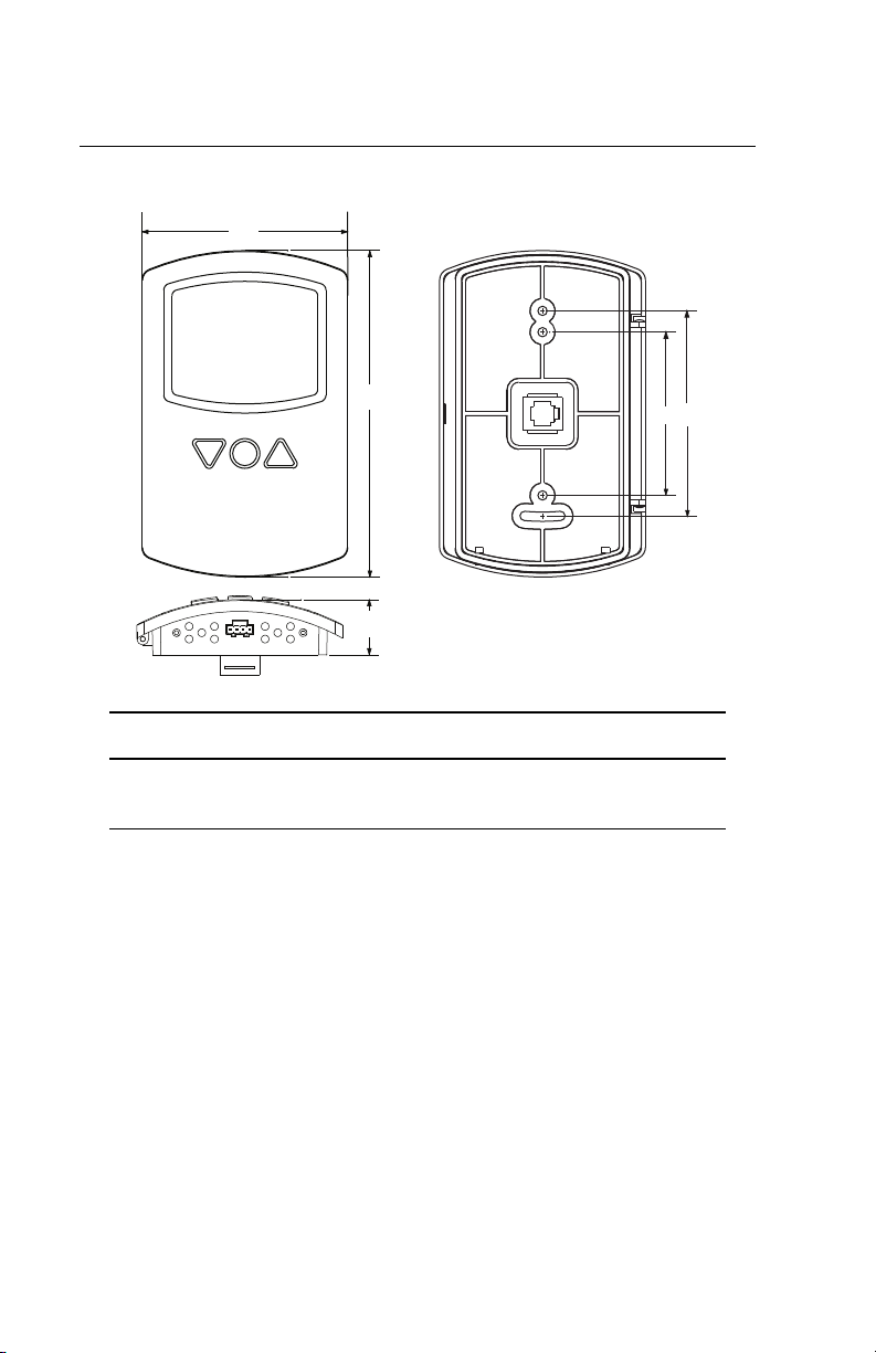
PC data port
The NetSensor is equipped with a PC data port located at the bottom
of the NetSensor housing. This port provides a temporary EIA-485
(formerly RS-485) connection to the digital network for network
setup or troubleshooting.
To use the port to connect to a computer, a means of converting the
EIA-485 signal to a USB or EIA-232 (formerly RS-232) signal will be
needed. The exact connection depends on the computer and the
operator workstation software (see also the instructions included
with those devices and software):
◆For USB (to WinControl or BACstage), use a KMD-5576 USB
Communicator (see the illustration above).
◆For EIA-232 to BACstage, use a third-party interface.
◆For EIA-232 to WinControl, use a KMD-5559 CommTalk and
KMD-5624 cable (or equivalent interface).
To use the PC data port:
1. Connect the keyed, flat end of the KMD-5624 NetSensor
interface cable (included with the KMD-5576 but not the KMD-
5559) to the port on the NetSensor.
2. Connect the RJ-12 end of the cable to the interface device that
converts the EIA-485 signal from the NetSensor into a USB or
EIA-232 signal.
3. Connect the suitable cable from the interface device to the
computer’s serial or USB port. Install any required software and
configure the port as necessary.
NetSensor PC port location and (USB) connection