manuals.online logo
Brands
  1. Home
  2. •
  3. Brands
  4. •
  5. Parker
  6. •
  7. Accessories
  8. •
  9. Parker 023-0475 User manual

Parker 023-0475 User manual

72-PHW-1034 R2.0 023-0475 Duct CO2 Sensor Spec&Install.docx RL 2022-02-09 Page 1 de 3
Parker Hannifin Canada
Micro Thermo Technologies TM
12855 Brault Street
Mirabel, QC J7J 0C4
Office phone 450-668-3033
Technical Data
023-0475 Duct CO2 Sensor specification & installation guide
Precision carbon dioxide
control/sensing
FEATURES:
• 2 Available Ranges
• Automatic Calibration Logic Program
• Analog out and menu driven set-up
• Solid-state reliability
• Small compact size
• Solid, reliable IP65 Polycarbonate enclosure
Description:
The duct CO2 transmitter uses a highly accurate and reliable non-dispersive infrared (NDIR) sensor in an attractive
enclosure with a gasketed, hinged cover for duct applications to monitor CO2 levels. The sensor uses dual
wavelength optics and LTA (long term adjustment) signal processing technology to deliver industry leading long term
accuracy and reliability. These features ensure optimum measurement stability for continual monitoring of either
supply or return air measuring.
Standard features include a field selectable output signal of either 4-20 mA, 0-5 Vdc or 0-10 V dc for the highest
versatility, programmable CO2 measurement span and easy menu operation for configuration.
Do not exceed device ratings. This product is not intended for life-safety applications.
SPECIFICATIONS:
Gas Type Detected .................................................................................. Carbon dioxide (CO2)
Sensor Type .......................................................... Dual channel non-dispersive infrared (NDIR)
Sensor Accuracy ................................................................. ±(30 ppm + 3% of measured value)
Measurement Range ..................................... 0-2000 ppm (default), adjustable 1000-10,000 ppm
Response Time ............................................................................................. 20 seconds (T63)
Warm-Up Time .......................................................................................................... 1 minute
Sensor Life Span ..................................................................................................... >15 years
Transmitter Accuracy .................. ±0.25% of span (including linearity, hysteresis and repeatability)
Power Supply ............................. 24 Vdc ±20% or 24 Vac ±10% (non-isolated half-wave rectified)
Protection Circuitry ....................................................... Reverse voltage and transient protected
Input Voltage Effect ..................................................... Negligible over specified operating range
Output Signal Type ........................................ 4-20 mA (3-wire), 0-5 or 0-10 Vdc (field selectable)
Current Consumption ............................. Current: 75 mA @ 24 Vdc max, 150 mA @ 24 Vac max
Voltage: .............................................................. 50 mA @ 24 Vdc max, 100 mA @ 24 Vac max
Output Drive @ 24 Vdc ............................................... Current: 550Ω max Voltage: 10,000Ω min
Ambient Operating Range ......................... 0 to 50°C (32 to 122°F), 0 to 95 %RH non-condensing
Storage Conditions ............................... -40 to 70°C (-40 to 158°F), 0 to 95 %RH non-condensing
Enclosure .................................................................. IP65 Polycarbonate UL94-V0 (NEMA 4X)
116mm W x 100mm H x 54mm D (4.6" x 3.9" x 2.1")
Wiring ............................................................................... Screw terminal block (14 - 22 AWG)
72-PHW-1034 R2.0 023-0475 Duct CO2 Sensor Spec&Install.docx RL 2022-02-09 Page 2 de 3
Installation:
The CO2 duct type sensor installs on the outside of a return air duct with the sampling tube inserted into the duct
through a 1-1/8” or 1-1/4” hole. Use the included foam plug to prevent air from entering the enclosure through the
conduit and causing an incorrect reading.
Mount the sensor in an easily accessible location in a straight section of duct at least five feet from corners and other
items that may cause disturbances in the air flow. Avoid areas where the detector is exposed to vibrations or rapid
temperature changes.
Wiring:
One 24VAC transformer can be used for many CO2 sensors only if the common side is on the same side of the
transformer (Calculate 3VA per CO2 sensor).
Settings:
The CO2 sensor 023-0475 reading range should be
factory set to 0-2000ppm, output set to 4-20mA. To
check setting you need to put the optional display.
To check press the Menu button. If these are not the
settings make the changes as follow:
OUTPUT switch to mA (4-20mA).
Press on MENU repeatedly to choose option, press
on UP or DOWN to change value. Value is saved
when MENU is pressed again.
CO2 Span = 2000 PPM (Range)
Self-Cal = On
When a value is changed, use the <MENU> key to
save it to memory and advance to the next menu
item. To exit press MENU until you see current CO2
ppm reading.
Connect the signal on 4-20mA mode with 470-0300
255 ohms resistor at the Sensor Node input. This
location helps to immune the reading variation of
PPM caused by the wire length.
Addition of the CO2 sensor model to MTA V6.X version
Already added in 7.3.0 version (updated in 8.6)
If then sensor model on key 373 :023-0475 Duct CO2 2000 ppm (4-20mA) Is not available, follow these steps:
Copy “CD2DT Duct Sensor Transmitter 20mA.bmp” in the “C:\Alliance\Images\SensorModels” folder (if you don’t
have the CD2DT bmp file use “CDDn Wall Sensor Transmitter 20mA.bmp”that is already in the folder “Images-
Sensor Models”may not be exactly the same.
72-PHW-1034 R2.0 023-0475 Duct CO2 Sensor Spec&Install.docx RL 2022-02-09 Page 3 de 3
Open Sensor Models in the Configure menu then click Add
Fill the forms as follow:
Click OK to save and close the Sensor Models window
Configuration of alarm limits
Add a 023-0475 sensor on the desired view, click on the sensor then on the Alarm Settings tab.
Set 2 is used to notify the CO2 Sensor malfunction.

Other Parker Accessories manuals

Parker TGSS 740 User manual

Parker

Parker TGSS 740 User manual

Parker SensoControl User manual

Parker

Parker SensoControl User manual

Parker TGSS 740 User manual

Parker

Parker TGSS 740 User manual

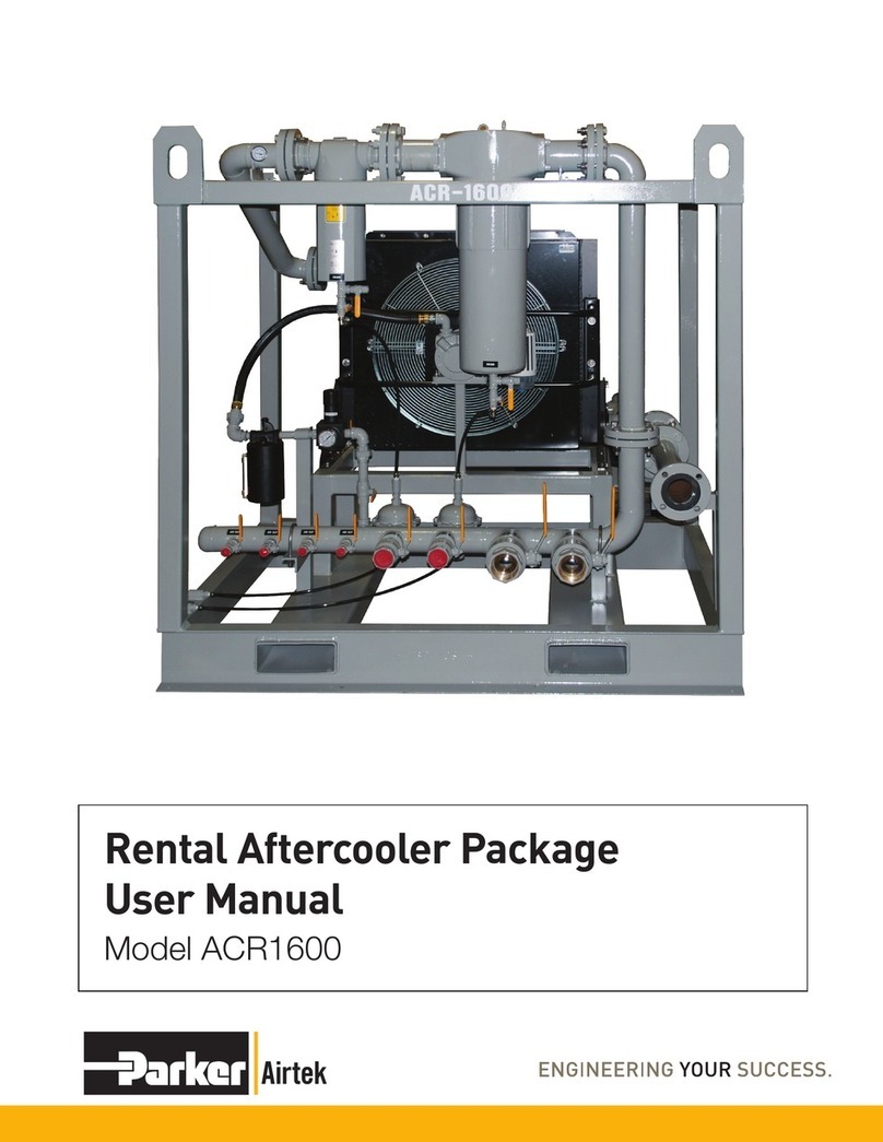
Parker Airtek ACR1600 User manual

Parker

Parker Airtek ACR1600 User manual

Parker Sporlan SD-245 User guide

Parker

Parker Sporlan SD-245 User guide

Parker SciLog WeighStation Assembly instructions

Parker

Parker SciLog WeighStation Assembly instructions

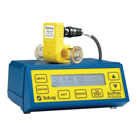
Parker SciLog SciPres Assembly instructions

Parker

Parker SciLog SciPres Assembly instructions

Parker QAC Datasheet

Parker

Parker QAC Datasheet

Parker Hypercool WR 007 Series User manual

Parker

Parker Hypercool WR 007 Series User manual

Parker GS100 User manual

Parker

Parker GS100 User manual

Parker UTS-ID User manual

Parker

Parker UTS-ID User manual

Parker SensoNODE Gold User manual

Parker

Parker SensoNODE Gold User manual

Parker PJC Series User manual

Parker

Parker PJC Series User manual

Parker TGSS User manual

Parker

Parker TGSS User manual

Parker TGSS 740 User manual

Parker

Parker TGSS 740 User manual

Parker ULRM 004 Maintenance and service guide

Parker

Parker ULRM 004 Maintenance and service guide

Parker UTS-G User manual

Parker

Parker UTS-G User manual

Parker RK 11-1570 User manual

Parker

Parker RK 11-1570 User manual

Parker 162703ECD User manual

Parker

Parker 162703ECD User manual

Parker Squibb Taylor SkyTrak SK2-1009-D Instruction manual

Parker

Parker Squibb Taylor SkyTrak SK2-1009-D Instruction manual

Popular Accessories manuals by other brands

Philips SAC2560W/10 Instructions for use

Philips

Philips SAC2560W/10 Instructions for use

Dorner 3200 Series Installation, maintenance & parts manual

Dorner

Dorner 3200 Series Installation, maintenance & parts manual

Byron DB305 Installation and operation instruction

Byron

Byron DB305 Installation and operation instruction

Leviton DECORA ODS10-IDI installation instructions

Leviton

Leviton DECORA ODS10-IDI installation instructions

Agilent Technologies 6060B Service manual

Agilent Technologies

Agilent Technologies 6060B Service manual

Craftsman 486.24611 owner's manual

Craftsman

Craftsman 486.24611 owner's manual

Nice Volo S Radio Instructions and warnings for the fitter

Nice

Nice Volo S Radio Instructions and warnings for the fitter

S+S Regeltechnik AERASGARD RLQ-W Operating Instructions, Mounting & Installation

S+S Regeltechnik

S+S Regeltechnik AERASGARD RLQ-W Operating Instructions, Mounting & Installation

Philips EasyAir SNS200 Quick installation guide

Philips

Philips EasyAir SNS200 Quick installation guide

GP H500 instruction manual

GP

GP H500 instruction manual

Wenglor P1MH Series operating instructions

Wenglor

Wenglor P1MH Series operating instructions

FrSky FAS100 ADV instruction manual

FrSky

FrSky FAS100 ADV instruction manual

Ericsson RBS 2206 Product description

Ericsson

Ericsson RBS 2206 Product description

STEINEL PROFESSIONAL HF 3600 Information

STEINEL PROFESSIONAL

STEINEL PROFESSIONAL HF 3600 Information

Avidsen 102436 quick start guide

Avidsen

Avidsen 102436 quick start guide

Innova DISCatcher Installation

Innova

Innova DISCatcher Installation

Veho pebble PZ12 manual

Veho

Veho pebble PZ12 manual

Crestron CH-TEMP-WM Operation guide

Crestron

Crestron CH-TEMP-WM Operation guide

manuals.online logo
manuals.online logoBrands
  • About & Mission
  • Contact us
  • Privacy Policy
  • Terms and Conditions

Copyright 2025 Manuals.Online. All Rights Reserved.