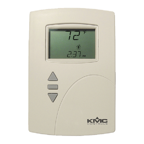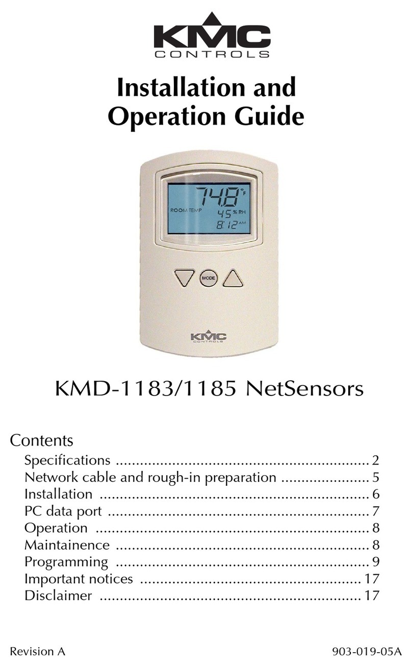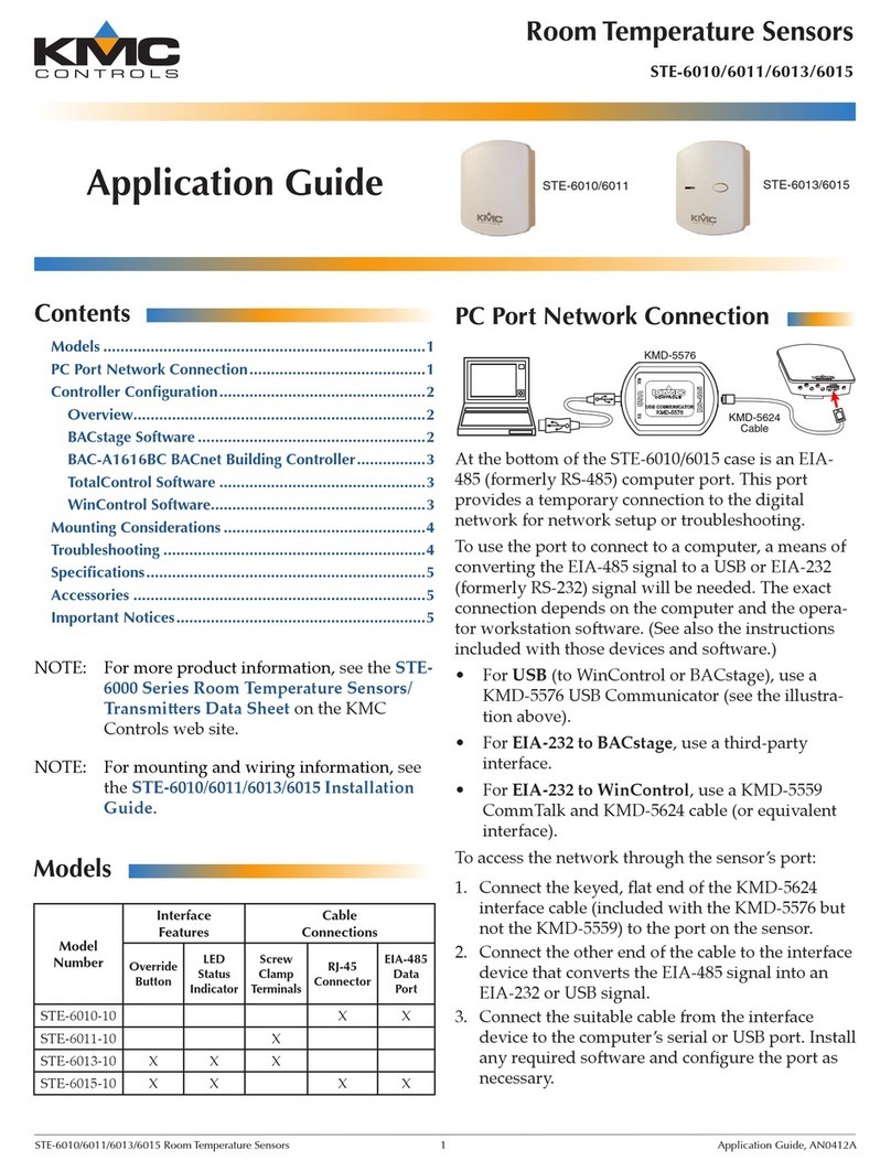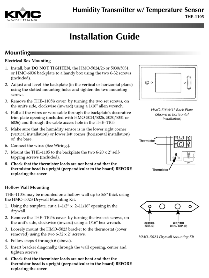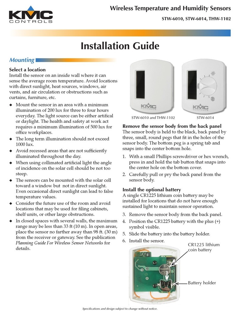
STW/THW Wireless Sensors Installation Guide 2918-019-02D
NOTE: Also consider the future use of the room
and avoid locations that may be later used
for ling cabinets, shelf units, or other
large obstructions that could block air
flow, light, and/or the RF signal.
Adequate RF Range/Path to the Gateway
For the RF signal, the maximum theoretical
straight-line distance between the gateway
and sensors is about 100 feet (30 meters).
However, in practice, the maximum distance will
be substantially reduced by obstacles in the
path, the shape of the room, sources of radio
interference, and placement/orientation of the
sensors and gateway!
See the application guide Planning for Wireless
Sensors Application Guide for important
information about proper placement of the
sensors and their gateway.
NOTE: To provide optimized placement
for all three sensor location factors,
repositioning the wireless gateway may
be necessary.
Adequate Light for Sensor Charging
To keep the sensor properly charged, mount the
sensor in an area with a minimum illumination
of 200 lux (e.g., typical light levels of interior
corridors, stairwells, storage rooms, or mechanical
rooms) for three to four hours every day. The
light source can be daylight (preferred) or articial
(dependent on type).
Articial lighting sources are not as effective in
keeping sensors charged as indirect daylight
because of spectrum and intensity differences.
LED lights (although energy efcient) are even less
effective in charging sensors than incandescent
or fluorescent lights. In an interior room that
has LED (only) lighting, a sensor should have
a battery installed as a backup. See (Optional)
Install Battery Backup on page 3.
Avoid recessed areas that are not sufciently
illuminated throughout the day. Avoid mounting
the sensor angled away from light sources. The
long-term illumination should not exceed 1000
lux (equivalent to outdoors on an overcast day).
The sensors can be mounted with the solar cell
toward a window but not in direct sunlight at any
time of the day since direct sunlight will give false
temperature values.
If fully charged, the sensor can transmit normally
for about four days in total darkness (without the
backup battery). If longer periods of darkness may
occur, install a battery as a backup. See (Optional)
Install Battery Backup on page 3.
Accurate Temp/Humidity Measurement
Install the sensor on an inside wall where it
can sense the average room temperature/
humidity and be away from direct sunlight, heat
sources, windows, air vents, and air circulation
obstructions (curtains, furniture, etc.).
See the Room Sensor and Thermostat Mounting
and Maintenance Application Guide for additional
mounting and troubleshooting information for
measuring temperature and humidity.
REMOVE BACKPLATE
To permanently mount the sensor, the cover must
be removed. The sensor cover is held to the black
backplate by three, small, round pegs that t in
the holes of the sensor body. The bottom peg is a
spring tab and snaps into the center bottom hole.
Tab
(Push to
Remove
the Cover)
Cover
Backplate
Mounting
Holes
1. With a small Phillips screwdriver or hex
wrench, press in and hold the tab button that
snaps into the center hole on the bottom
cover.
