manuals.online logo
Brands
  1. Home
  2. •
  3. Brands
  4. •
  5. KMC Controls
  6. •
  7. Controllers
  8. •
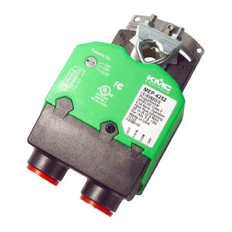
  9. KMC Controls MEP-46 Q Series User manual

KMC Controls MEP-46 Q Series User manual

1
DESCRIPTION AND APPLICATION
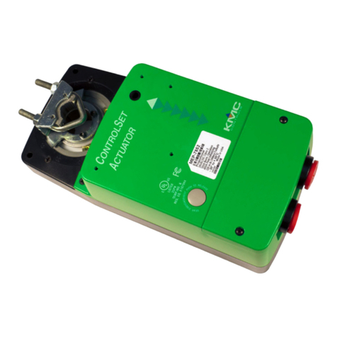
These compact but powerful direct-coupled ControlSet®
actuators provide 90° rotation within three seconds. A
minimum torque of 54 in-lb. is available over the 95° angular
rotation. These actuators are designed for dampers or
valves in critical HVAC, laboratory fume hood, and life-safety
applications.
Efcient, durable, capacitor-driven fail-safe operation (in
MEP-4652Q/4672Q) with switch-selectable direction provides
consistent torque in both powered and fail-safe modes.
The actuators offer proportional or two-position control.
Two-position control mode is designed for use with on/off
switches, thermostats, or controller outputs.
Proportional control mode accepts either a 0–10 or 2–10 VDC
control signal input from a thermostat or controller. With an
external 500 ohm resistor, a 0–20 or 4–20 mA control signal
is also accepted. A switch-selectable, 0–5 or 0–10 (or 1–5
or 2–10) VDC voltage feedback output is proportional to the
actuator position and is standard on all models. “Anti-jitter”
circuitry signicantly reduces hunting and needless wear
(from unnecessary miniscule position changes caused by
undamped analog input signals) on the actuator, valve, or
damper components. A user-initiated, auto-mapping feature
provides more precise equipment control by reassigning the
input signal range over a reduced rotation range. The feature
also provides “soft stall” protection (from stalling hard against
a physical stop) that extends actuator life.
MEP-4622Q and MEP-4672Q models also have two built-in
SPDT auxiliary switches for remote position indication or an
auxiliary equipment interface. One switch is fully adjustable (0
to 90°) and the other is xed at 10° from full CW direction. A
three-foot cable is included with the switches.
All actuators mount directly to 1/4- to 5/8-inch (6 to 16
mm) round shafts or 1/4- to 7/16-inch (6 to 11 mm) square
shafts, eliminating the need for expensive and complicated
linkages. A non-rotation bracket, to prevent lateral movement,
is included with each actuator. A gear disengagement button
allows easy manual positioning of the actuator.
Specifications and design subject to change without notice
FEATURES
◆Brushless DC motor technology
◆Each model provides proportional or two-position control
◆90° rotation within three seconds (powered or optional
fail-safe)
◆54 in-lb. is available over the 95° angular rotation
◆Optional fail-safe (in MEP-4652Q and MEP-4672Q models)
◆The fail-safe option has switch-selectable direction and
can be turned off temporarily for testing purposes or
permanently if desired
◆Proportional mode includes “anti-jitter” circuitry
◆Auto-mapping of the full input-signal range over a reduced
actuator stroke provides a “soft stall” protection feature
that extends actuator life
◆Switch-selectable 0/1–5 or 0/2–10 VDC feedback is stan-
dard on all models
◆MEP-4622Q and MEP-4672Q models have one fully adjust-
able and one xed built-in SPDT auxiliary switches
◆Direct mounting to standard shaft sizes, gear disengage-
ment button, and adjustable mechanical end stop
(Size Shown Relative
to a Quarter)
MEP-46xxQ Series
Quick-Running (3-Second) Actuators (54 in-lb.)
2
MODELS
MODEL NUMBER FAIL SAFE AUXILIARY SPDT
SWITCHES*
ELECTRICAL
CONNECTIONS**
NON-ROTATION
BRACKET
MEP-4602Q No No Terminals HMO-4002
MEP-4622Q No Yes Cables HMO-4001
MEP-4652Q Yes No Terminals HMO-4002
MEP-4672Q Yes Yes Cables HMO-4001
*One switch is fully adjustable (0 to 90°) and the other is xed at 10° from full CW direction.
**Connections are made on either xed terminals that accept 12–26 AWG wiring or (on models with auxiliary switches)
prewired 3-foot, 18 AWG cables. Models with cables have the larger HMO-4001 “T” non-rotation bracket.
DIMENSIONS
Dimensions are in
inches (mm)
6.000
(152.4)
1.625
(41.3)
2.812
(71.4) 1.563
(39.7)
3.406
(86.5)
3
Hardware Features
Control Signal
Proportional 0 to 10 VDC or 2 to 10 VDC, switch
selectable
Two-position See Supply Voltage
Supply Voltage 24 VAC (+20%/–15%),
Class 2 only, or 22–35 VDC
Supply Frequency 50/60 Hz for VAC operation
Supply Power 3 VA normal operation (all), 19 VA
peak initializing (fail-safe models)
Initialization Time Up to 30 seconds before fail safe
(MEP-4652Q/4672Q) is sufcient-
ly charged, but the actuator will
respond normally to control signal
commands during the charge time
Bridge Time Less than 1 second delay for fail-
safe to activate upon loss of power
Feedback Output 0/1 to 5 VDC or 0/2 to 10 VDC
(switch selectable, standard on all
models)
SPECIFICATIONS
Auxiliary Switches
2 SPDT 1 adjustable 0 to 90° and 1 xed at
10° from full CW direction (MEP-
4622Q/4672Q only)
Rating 6 A resistive load (3 A motor load)
@ 250 VAC
Fail-Safe Control Switch selectable, CW/OFF/CCW
Fail-Safe Type (Electronic) capacitor driven
Angular Rotation 0 to 95°, fully adjustable with me-
chanical stop
Position Indication Visual indicator, 0° to 95°
Running Time 90° in 3 seconds (powered or op-
tional fail-safe)
Torque 54 in-lbs. (6 N•m)
Noise Level < 60 dBA max. at 1 meter
NOTE: When the 0–10 VDC input is selected, selectable
feedback options are 0–5 or 0–10 VDC. When the
2–10 VDC input is selected, feedback options are
1–5 or 2–10 VDC.
Non-Rotation Bracket
(HMO-4002)
Gear Disengagement
Lever
Mounting Surface
Proportional
Control
Contact Position with
#2 Switch set for CW:
Open = CCW Rotation
Closed = CW Rotation
Contact Position with
#2 Switch set for CCW:
Open = CW Rotation
Closed = CCW Rotation
Power Supply
24 VAC/VDC
Feedback Out
0/1–5 or 0/2–10
2-Postion
Control
4
© 2018 KMC Controls, Inc.; KMC Controls®and ControlSet®are registered trademarks of KMC Controls 039-035-03B
KMC Controls, Inc.
19476 Industrial Drive
New Paris, IN 46553
574.831.5250
www.kmccontrols.com
[email protected]
MORE INFORMATION
For mounting, wiring, auxiliary switches, feedback/direction
selectors, actuator/signal range reset (auto-mapping), and
other information, see the MEP-46xxQ Series Installation
Guide.
For torque selection, accessories, troubleshooting, and other
information, see the MEP-4xxx Applications Guide.
Installation
Connections
Power/Signal Prewired 3-foot, 18 AWG cable or
xed wire clamp terminal block,
12–26 AWG, copper (see Models on
page 2)
Aux. Switches 3-foot 18 AWG cable
Mounting Direct to 1/4 to 5/8 inches (6 to 16
mm) round or 1/4 to 7/16 inches (6
to 11 mm) square shaft by adjusta-
ble “V” bolt and supplied non-rota-
tion bracket; minimum recommend-
ed damper shaft length is 1-5/8
inches
Brackets HMO-4001 or HMO-4002 non-rota-
tion bracket included*
Dimensions 6.000 x 2.812 x 3.406 inches
(152.4 x 71.4 x 86.5 mm)—see
Dimensions on page 2
Weight 1.5 lb. (0.68 kg)
Enclosure UL94-5VA flame-retardant polymer,
NEMA 2 and IP54—to guarantee
IP54, install an HMO-4521 liq-
uid-tight cord grip
Servicing Maintenance free
Environmental Limits
Operating –22 to 131° F (–30 to 55° C)
Shipping –40 to 176° F (–40 to 80° C)
Humidity 5 to 95% RH (non-condensing)
*NOTE: The two holes at the top of the actuator are NOT
for use in direct-coupled applications. They are for
remote mounting, such as with the optional HLO-
4001 crank arm kit.
Warranty, Quality, and Approvals
KMC Limited Warranty 5 years (from mfg. date code)
Quality Standard ISO 9001
Approvals
UL UL 873 Temperature Indicating and
Regulating Equipment
FCC FCC Class A, Part 15, Subpart B and
complies with Canadian ICES-003
Class A*
*This device complies with part 15 of the FCC Rules.
Operation is subject to the following two conditions: (1) This
device may not cause harmful interference, and (2) this device
must accept any interference received, including interference
that may cause undesired operation.

This manual suits for next models

4

Other KMC Controls Controllers manuals

KMC Controls BAC-5901C-AFMS User manual

KMC Controls

KMC Controls BAC-5901C-AFMS User manual

KMC Controls KMD-7001 Original operating instructions

KMC Controls

KMC Controls KMD-7001 Original operating instructions

KMC Controls KMD-5205 Operating instructions

KMC Controls

KMC Controls KMD-5205 Operating instructions

KMC Controls MCP-1020 Series User manual

KMC Controls

KMC Controls MCP-1020 Series User manual

KMC Controls CTE-3017 User manual

KMC Controls

KMC Controls CTE-3017 User manual

KMC Controls MCP-1160 Series User manual

KMC Controls

KMC Controls MCP-1160 Series User manual

KMC Controls BAC-7001 User manual

KMC Controls

KMC Controls BAC-7001 User manual

KMC Controls CSC-3501 User manual

KMC Controls

KMC Controls CSC-3501 User manual

KMC Controls MEP-4201 User manual

KMC Controls

KMC Controls MEP-4201 User manual

KMC Controls CEE-3009 User manual

KMC Controls

KMC Controls CEE-3009 User manual

KMC Controls MEP-4201 User manual

KMC Controls

KMC Controls MEP-4201 User manual

KMC Controls MEP-3001 Operating instructions

KMC Controls

KMC Controls MEP-3001 Operating instructions

KMC Controls FlexStat BAC-12 63 Series User manual

KMC Controls

KMC Controls FlexStat BAC-12 63 Series User manual

KMC Controls CSC 3000 Series User guide

KMC Controls

KMC Controls CSC 3000 Series User guide

KMC Controls SimplyVAV BAC-8205 User manual

KMC Controls

KMC Controls SimplyVAV BAC-8205 User manual

KMC Controls CSC 3000 Series User guide

KMC Controls

KMC Controls CSC 3000 Series User guide

KMC Controls AppStat User manual

KMC Controls

KMC Controls AppStat User manual

KMC Controls BAC-9300 Series User manual

KMC Controls

KMC Controls BAC-9300 Series User manual

KMC Controls BAC-7302 Operating instructions

KMC Controls

KMC Controls BAC-7302 Operating instructions

KMC Controls KMD-5210 Operating instructions

KMC Controls

KMC Controls KMD-5210 Operating instructions

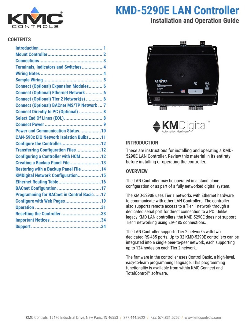
KMC Controls KMDigital KMD-5290E Operating instructions

KMC Controls

KMC Controls KMDigital KMD-5290E Operating instructions

KMC Controls KMD-5831 Original operating instructions

KMC Controls

KMC Controls KMD-5831 Original operating instructions

KMC Controls BAC-7401 Operating instructions

KMC Controls

KMC Controls BAC-7401 Operating instructions

KMC Controls CSC-1001 User manual

KMC Controls

KMC Controls CSC-1001 User manual

Popular Controllers manuals by other brands

alphainnoTec Luxtronik operating instructions

alphainnoTec

alphainnoTec Luxtronik operating instructions

digitalview 41710002X-3 instructions

digitalview

digitalview 41710002X-3 instructions

FeiYu Tech 41AP quick start guide

FeiYu Tech

FeiYu Tech 41AP quick start guide

Kieback&Peter FBR5 manual

Kieback&Peter

Kieback&Peter FBR5 manual

Oriental motor CRD514-KD Information

Oriental motor

Oriental motor CRD514-KD Information

Icom IP1000C quick start guide

Icom

Icom IP1000C quick start guide

Multitech CommPlete MR9600-100 user guide

Multitech

Multitech CommPlete MR9600-100 user guide

PowerWalker AVR 1200 quick start guide

PowerWalker

PowerWalker AVR 1200 quick start guide

Tolomatic BCS10 Quick start quide

Tolomatic

Tolomatic BCS10 Quick start quide

Delta VFD-L user manual

Delta

Delta VFD-L user manual

AutomationDirect NITRA PNEUMATICS Setup instructions

AutomationDirect

AutomationDirect NITRA PNEUMATICS Setup instructions

Casa Fan ST4-150 II Mounting and operating manual

Casa Fan

Casa Fan ST4-150 II Mounting and operating manual

Life Smart LS143 quick start guide

Life Smart

Life Smart LS143 quick start guide

COLORKINETICS Data Enabler IntelliPower installation instructions

COLORKINETICS

COLORKINETICS Data Enabler IntelliPower installation instructions

Control Technologies 2646 MultiPro installation guide

Control Technologies

Control Technologies 2646 MultiPro installation guide

Delta DAC-1600 installation guide

Delta

Delta DAC-1600 installation guide

WorkPro Nemesis 136 User instructions

WorkPro

WorkPro Nemesis 136 User instructions

Iron logic Matrix III NET user manual

Iron logic

Iron logic Matrix III NET user manual

manuals.online logo
manuals.online logoBrands
  • About & Mission
  • Contact us
  • Privacy Policy
  • Terms and Conditions

Copyright 2025 Manuals.Online. All Rights Reserved.