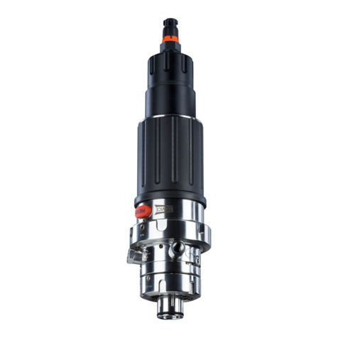
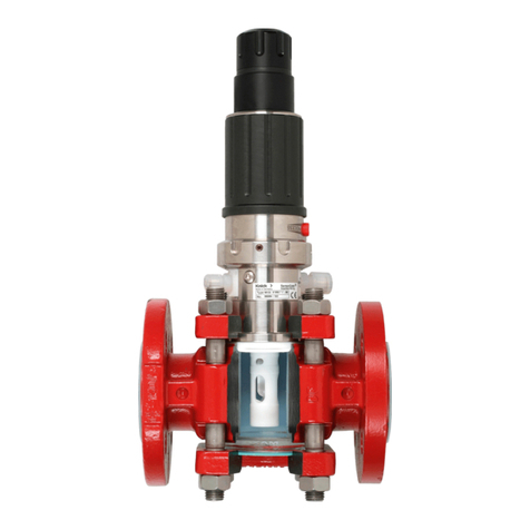
Knick SensoGate WA131 User manual

User Manual SensoGate WA131
Retractable Fitting
www.knick.de
Read before installation.
Keep for future use.

SensoGate WA131
2
Supplemental Directives
READ AND SAVE THIS DOCUMENT FOR FUTURE REFERENCE. BEFORE ATTEMPTING TO ASSEMBLE,
INSTALL, OPERATE OR MAINTAIN THE PRODUCT, PLEASE ENSURE A COMPLETE UNDERSTANDING OF
THE INSTRUCTIONS AND RISKS DESCRIBED HEREIN. ALWAYS OBSERVE ALL SAFETY INFORMATION.
FAILURE TO COMPLY WITH INSTRUCTIONS IN THIS DOCUMENT COULD RESULT IN SERIOUS INJURY
AND/OR PROPERTY DAMAGE. THIS DOCUMENT IS SUBJECT TO CHANGE WITHOUT NOTICE.
These supplemental directives explain how safety information is laid out in this document and
what content it covers.
Safety Chapter
This document's safety chapter is designed to give the reader a basic understanding of safety. It
illustrates general hazards and gives strategies on how to avoid them.
Warnings
This document uses the following warnings to indicate hazardous situations:
Symbol Category Meaning Remark
WARNING Designates a situation that can lead to death or serious
(irreversible) injury.
The warnings contain
information on how to
avoid the hazard.
CAUTION Designates a situation that can lead to slight or moderate
(reversible) injury.
None NOTICE Designates a situation that can lead to property or
environmental damage.
Symbols Used in this Document
Symbol Meaning
Reference to additional information
Interim or final result in instructions for action
Sequence of figures attached to an instruction for action
Item number in a figure
Item number in text

SensoGate WA131
3
Table of Contents
1 Safety............................................................................................................................................. 5
1.1 Intended Use ......................................................................................................................................................... 5
1.2 Personnel Requirements ................................................................................................................................... 5
1.3 Safeguards.............................................................................................................................................................. 6
1.4 Residual Risks ........................................................................................................................................................ 7
1.5 Safety Accessories................................................................................................................................................ 8
1.6 Hazardous Substances ....................................................................................................................................... 9
1.7 Operation in Explosive Atmospheres ........................................................................................................... 9
1.7.1 Possible Ignition Hazards During Installation and Maintenance.......................................... 9
1.7.2 Possible Ignition Hazards During Operation................................................................................ 10
1.8 Safety Training ...................................................................................................................................................... 10
1.9 Maintenance and Spare Parts.......................................................................................................................... 10
2 Product .......................................................................................................................................... 11
2.1 Package Contents ................................................................................................................................................ 11
2.2 Product Identification......................................................................................................................................... 11
2.2.1 Example of a Version ............................................................................................................................. 11
2.2.2 Product Code ........................................................................................................................................... 12
2.3 Nameplates ............................................................................................................................................................ 14
2.4 Symbols and Markings....................................................................................................................................... 16
2.5 Design and Function........................................................................................................................................... 16
2.5.1 Retractable Fitting.................................................................................................................................. 17
2.5.2 Drives and Sensor Holders.................................................................................................................. 18
2.5.3 Process Connections ............................................................................................................................. 18
2.5.4 Immersion Tubes .................................................................................................................................... 19
2.6 Permissible Changes........................................................................................................................................... 19
2.7 SERVICE/PROCESS Limit Positions ................................................................................................................. 20
2.7.1 Service and Process Position.............................................................................................................. 20
2.7.2 Limit Signals ............................................................................................................................................. 21
3 Installation .................................................................................................................................... 22
3.1 Retractable Fitting: Installation....................................................................................................................... 22
3.2 Safety Accessories: Installation ....................................................................................................................... 22
3.3 Outlet Hose: Installation.................................................................................................................................... 23
3.4 Inlet Hose (Option): Installation...................................................................................................................... 23
3.5 Pneumatic Control: Installation ...................................................................................................................... 24
4 Commissioning ............................................................................................................................. 25
5 Operation ...................................................................................................................................... 26
5.1 Moving into the Process Position (PROCESS Limit Position) ................................................................ 26
5.2 Moving into the Service Position (SERVICE Limit Position)................................................................... 26
5.3 Installing and Removing Sensors................................................................................................................... 27
5.3.1 Safety Instructions on Installing and Removing Sensors......................................................... 27
5.3.2 Solid-Electrolyte Sensor, Short Immersion Depth: Installation ............................................. 27
SensoGate WA131
4
5.3.3 Solid-Electrolyte Sensor, Short Immersion Depth: Removal .................................................. 28
5.3.4 Solid-Electrolyte Sensor, Long Immersion Depth: Installation .............................................. 29
5.3.5 Solid-Electrolyte Sensor, Long Immersion Depth: Removal ................................................... 30
5.3.6 Liquid-Electrolyte Sensor: Installation ............................................................................................ 31
5.3.7 Liquid-Electrolyte Sensor: Removal................................................................................................. 33
6 Maintenance ................................................................................................................................. 34
6.1 Inspection............................................................................................................................................................... 34
6.1.1 Inspection and Maintenance Intervals........................................................................................... 34
6.1.2 Knick Premium Service......................................................................................................................... 34
6.2 Preventive Maintenance.................................................................................................................................... 35
6.2.1 Approved Lubricants............................................................................................................................. 35
6.2.2 Characteristics of Process-Wetted Materials................................................................................. 35
6.3 Corrective Maintenance .................................................................................................................................... 36
6.3.1 Corrective Maintenance Safety Instructions ................................................................................ 36
6.3.2 Drive Unit: Removal............................................................................................................................... 36
6.3.3 Drive Unit: Assembly............................................................................................................................. 37
6.3.4 Immersion Tube: Removal .................................................................................................................. 38
6.3.5 Immersion Tube: Installation.............................................................................................................. 39
6.3.6 Calibration Chamber: Removal ......................................................................................................... 40
6.3.7 Calibration Chamber: Installation..................................................................................................... 41
6.3.8 Knick Repair Service .............................................................................................................................. 41
7 Troubleshooting ........................................................................................................................... 42
7.1 Malfunction States............................................................................................................................................... 42
8 Removal from Operation ............................................................................................................. 43
8.1 Retractable Fitting: Removal............................................................................................................................ 43
8.2 Returns..................................................................................................................................................................... 43
8.3 Disposal ................................................................................................................................................................... 43
9 Spare Parts, Accessories, and Tools............................................................................................. 44
9.1 Seal Kits.................................................................................................................................................................... 44
9.2 Spare Parts.............................................................................................................................................................. 46
9.3 Accessories ............................................................................................................................................................. 47
9.4 Tools.......................................................................................................................................................................... 51
10 Dimension Drawings .................................................................................................................... 52
11 Specifications................................................................................................................................ 58

SensoGate WA131
5
1 Safety
This document contains important instructions for the use of the product. Always follow all
instructions and operate the product with caution. If you have any questions, please contact
Knick Elektronische Messgeräte GmbH & Co. KG (sometimes hereafter referred to as "Knick")
using the information provided on the back page of this document.
1.1 Intended Use
The SensoGate WA131 is a retractable fitting for installation in boilers, tanks, and pipes. The product is
used to mount a sensor for measuring process parameters. The sensor is immersed in the process
medium by the SensoGate WA131. The SensoGate WA131 is pneumatically operated.
Cleaning, calibration, or sensor replacement under process conditions by the customer (hereinafter
sometimes referred to as the "operating company") may be conducted, subject to the requirements
set forth herein, by placing the product into the service position (SERVICE limit position).
If the product is used with any product or part not authorized by Knick, the operating company
assumes all risks and liabilities related thereto.
The SensoGate WA131 can be used with the following sensor types:
Solid-electrolyte sensors Outer diameter 12mm, length225 mm, sensor head thread PG13.5
Liquid-electrolyte sensors Outer diameter 12mm, length 250mm
Optical sensors Outer diameter 12mm
For further information, refer to the applicable documentation of the sensor manufacturer.
The defined operating conditions must be observed when using this product. ➜Specifications, p. 58
Thanks to its modular design, the SensoGate WA131 can be adapted to changed conditions by the
customer.
➜Permissible Changes, p. 19
USE CAUTION AT ALL TIMES WHEN INSTALLING, USING, MAINTAINING OR OTHERWISE INTERACTING WITH
THE PRODUCT. ANY USE OF THE PRODUCT EXCEPT AS SET FORTH HEREIN IS PROHIBITED, AND MAY RESULT
IN SERIOUS INJURY OR DEATH, AS WELL AS DAMAGE TO PROPERTY. THE OPERATING COMPANY SHALL BE
SOLELY RESPONSIBLE FOR ANY DAMAGES RESULTING FROM OR ARISING OUT OF AN UNINTENDED USE OF
THE PRODUCT.
The SensoGate WA131-X version is certified for operation in hazardous locations.
➜Operation in Explosive Atmospheres, p. 9
1.2 Personnel Requirements
The operating company shall ensure that any personnel using or otherwise interacting with the
product is adequately trained and has been properly instructed.
The operating company shall comply and cause its personnel to comply with all applicable laws, regu-
lations, codes, ordinances and relevant industry qualification standards related to product. Failure to
comply with the foregoing shall constitute a violation of operating company’s obligations concerning
the product, including but not limited to an unintended use as described in this document.
Table of contents
Other Knick Industrial Equipment manuals

Knick
Knick WA111 User manual

Knick
Knick SensoGate WA131MH User manual

Knick
Knick ProLine P16800 User manual

Knick
Knick Ceramat WA160 User manual

Knick
Knick ARD 250 User manual

Knick
Knick SensoGate WA 132 Series User manual

Knick
Knick Ceramat WA 153 User manual

Knick
Knick Ceramat WA 154 User manual

Knick
Knick ARD50EL User manual