Kobalt 19003 User manual

1
Serial Number Purchase Date
Questions, problems, missing parts? Before returning to your retailer, call our
customer service department at 888-3KOBALT (888-356-2258), 8 a.m. - 8 p.m., EST,
ATTACH YOUR RECEIPT HERE
ITEM #2368777
ITEM #5193450
ITEM #5193457
MODEL #19003
MODEL #19190
MODEL #19197
28-IN 2-DOOR
WALL CABINET
Español p. 14
KOBALT and logo design are trademarks or registered
trademarks of LF, LLC. All rights reserved.
SS22097
A STEP-BY-STEP VIDEO ON HOW
TO ASSEMBLE & THE TOOLS
NEEDED
SCAN ME

2
PRODUCT SPECIFICATIONS
TABLE OF CONTENTS
COMPONENTS SPECIFICATIONS
Maximum load for bottom shelf
Maximum load for adjustable shelf
Maximum total load
Note: Specify the item number when ordering the product due to the different colors:
COLOR ITEM # MODEL #
Silver
Blue
Black
2368777
5193450
5193457
19003
19190
19197
50 lbs.
100 lbs.
150 lbs.
Package Contents...........................................................................................................................3
Hardware Contents..........................................................................................................................4
Safety Information. .........................................................................................................................5
Preparation ....................................................................................................................................5
Assembly Instructions......................................................................................................................6
Troubleshooting ..........................................................................................................................12
Warranty .......................................................................................................................................12
Replacement Parts List ................................................................................................................13

PACKAGE CONTENTS
3
A
B
C
D
E
F
G
H
I
J
K
1
1
1
1
1
1
1
1
1
1
1
Left back panel
Right back panel
Left side panel
Right side panel
Base panel
Top panel
Bottom shelf
Adjustable shelf
Left door
Right door
Cabinet bracket
PART DESCRIPTION QUANTITY
F
D
J
I
E
G
H
C
K
AB

HARDWARE CONTENTS (shown actual size)
4
Lock
(Preassembled to right door(J))
Qty. 1
Key
(Preassembled to locking bar of right door(J))
Qty. 2
AA BB CC DD
EE FF GG HH
II JJ
MM NN
KK LL
5/16 - 18 x 3/4 in.
Carriage bolt
Qty. 4
5/16 - 18 in.
Flange nut
Qty. 4
1 in. Flat washer
Qty. 6
ST4.8 x 10 mm
Screw
Qty. 8+2
Cabinet spacer
Qty. 2
1/4 - 20 x 1/2 in.
Truss screw
Qty. 2
1/4 - 20 in. Hex nut
Qty. 2
Outside cabinet
bracket
Qty. 2
Inside cabinet
bracket
Qty. 2
5 x 15 x 1.2 mm
Washer
Qty. 4
D8 x 50.8 mm
Expansion tube
Qty. 4
ST4.8 x 57 mm Pan
head tapping screw
Qty. 4

SAFETY INFORMATION
Please read and understand this entire manual before attempting to assemble or operate this
product. Failure to follow may result in serious injury. Save all warnings and instructions for future
reference.
5
• Do not stand on, step on, or alter this unit for anything outside the designed function of storage.
• Use care when handling and assembling metal plates.
• The metal may have sharp edges or corners. The use of protective gloves is recommended.
• Always remember to use proper lifting techniques when moving the boxed or assembled unit.
• When mounting unit to wall, ensure studs are plumb and square.
• When mounting multiple units to a wall, check local building codes or consult with a contractor
to determine the maximum load rating for your desired installation.
• Do not exceed maximum load capacities listed in Product Specifications on Page 2.
• When storing articles, equally distribute loads.
• Assemble only according to these instructions. Improper assembly can create hazards.
• Do not store flammable liquids in the unit unless they are secured in an approved container.
• Do not store gasoline in the unit under any circumstances.
• Do not assemble and use when tired or under the influence of drugs or medication.
• The product is not a toy. Do not allow children to play with, on or near the unit.
• Always use common sense and be cautious when using this product.
CAUTION
WARNING
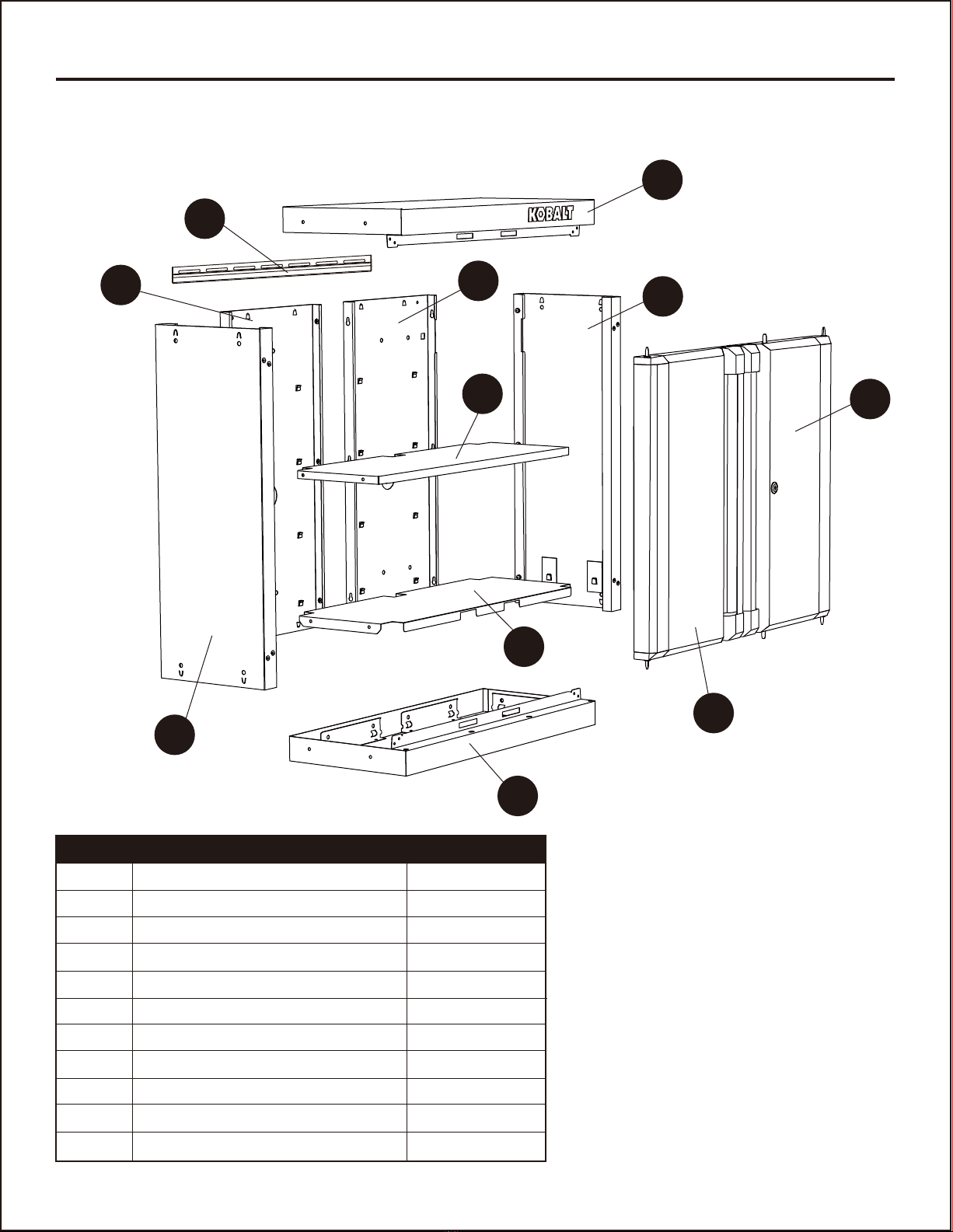
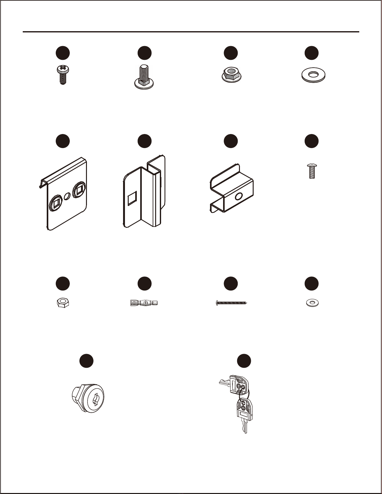
Before beginning assembly of product, make sure all parts are present. Compare parts with package
contents list and hardware contents above. If any part is missing or damaged, do not attempt to
assemble the product. Contact customer service for replacement parts.
It is recommended that this product to be assembled on a clean, soft surface, such as a piece of
cardboard.
Estimated Assembly Time: 30 minutes (does not include unpacking time)
Tools Required for Assembly (not included): Drill, PH2 screwdriver, Rubber mallet, Adjustable Wrench
PREPARATION
tooltip
tooltip

ASSEMBLY INSTRUCTIONS
6
1. Slide preassembled screws in left back
panel (A) into key slots of right back
panel (B) to connect the two back
panels together. Tighten the screws.
Note: Be sure to keep the back panels on a
soft surface, such as carpeting or a piece of
cardboard, to protect them from scratches.
2. Slide preassembled screws into key
slots of the assembled unit from Step
1 to connect left side panel (C) and
right side panel (D) to the assembled
unit. Tighten the screws.
1
2
B
A
B
A
C
A
A
B
D
C

ASSEMBLY INSTRUCTIONS
7
3. Align the base panel (E) with the
assembled unit from Step 2 carefully. Tap
the base panel (E) into the unit until the
clips are secured tightly. Repeat this step
to attach the top panel (F) to the
assembled unit.
Note: Recommended to use a rubber
mallet to tap the components together.
Hardware Used
4. Check and verify the holes in front edge of
base panel (E) and top panel (F) are
aligned with the holes in left side panel
(C) and right side panel (D). If not, check
and make sure the base panel (E) and
top panel (F) are located at the right
place. Tighten the ST4.8 x 10 mm screws
(AA) to the holes to make the unit
securely fixed. Place the cabinet upright.
AA x 8ST4.8 x 10 mm
Screw
4C
F
D
E
AA
Before After
3
C
E
F
D

ASSEMBLY INSTRUCTIONS
8
Hardware Used
5. Use 5/16 - 18 x 3/4 in. carriage bolts (BB),
5/16 - 18 in. flange nuts (CC), and 1 in.
flat washers (DD) to secure outside
cabinet brackets (EE) and inside cabinet
brackets (FF) to the cabinet. Screw
cabinet spacers (GG) with 1/4 - 20 x 1/2
in. truss screws (HH), 1 in. flat washers
(DD) and 1/4 - 20 in. hex nuts (II) to the
back of the assembled unit.
5
CC
DD
A
FF EE
II
GG
HH DD
BB
BB x 4
Back View
Front View
5/16 - 18 x 3/4 in.
Carriage bolt
CC x 4
5/16 - 18 in.
Flange nut
DD x 61 in. Flat washer
EE x 2
Outside cabinet
bracket
FF x 2
Inside cabinet
bracket
GG x 2
Cabinet
spacer
HH x 2
1/4 - 20 x 1/2 in.
Truss screw
II x 2
1/4 - 20 in. Hex nut
GG
EE
A
FF
C

tooltiptooltip
tooltiptooltiptooltip
tooltip
ASSEMBLY INSTRUCTIONS
9
6. Install the bottom shelf (G) by tipping it to
the side and inserting it into the cabinet.
With bottom shelf (G) at an angle, align
the cut-outs on the bottom shelf (G) with
the back seams caused by side panels (C
and D) and back panels (A and B).
Carefully lower the bottom shelf (G),
ensuring the front of the bottom shelf (G)
goes over the front flange of the base
panel (E).
Determine the location for the adjustable
shelf (H). Hold the adjustable shelf (H) at
an angle to make it easier to install.
Please make sure adjustable shelf (H)
snaps into the hooks on the unit.
Note: If the hooks are flatted during
assembly, use a slotted screwdriver (not
included) to recover them.
6
A
H
C
C
7. Lift and pull the L-shaped pivot pin on the
edge of the left door (I), aligning the
assembling holes of the base panel (E)
and top panel (F), then release. Repeat
for right door (J).
7
IJ
F
H
GD
E
E
tooltip

ASSEMBLY INSTRUCTIONS
10
8. Determine the location for the cabinet
bracket (K). If you plan to hang the unit onto
drywall, please follow below steps. Feed
ST4.8 x 57 mm pan head tapping screws
(KK) through 5 x 15 x 1.2 mm washers (LL)
and cabinet bracket (K). Drill the ST4.8 x 57
mm pan head tapping screws (KK) to the
wood stud.
Note: Ensure the cabinet bracket (K) is installed horizontally, or the two doors will probably not be
properly aligned after step 9.
8
K
Hardware Used
KK x 2
x 4
ST4.8 x 57 mm Pan
head tapping screw
LL x 2
5 x 15 x 1.2 mm
Washer
Hardware Used
KK ST4.8 x 57 mm Pan
head tapping screw
x 4
JJ D8 x 50.8 mm Expansion tube
LL x 4
5 x 15 x 1.2 mm
Washer
LL
JJ
KK
Stud wall
Stud wall
Cement wall
K
Cement wall
16"
OPTIONAL
If you plan to hang the unit onto cement wall,
please follow below steps. Drill 4 holes (with
the diameter of about 8.5 mm) in the cement
wall. Insert D8 x 50.8 mm expansion
tubes(JJ) in the drilled holes. Feed ST4.8 x
57 mm pan head tapping screws (KK)
through 5 x 15 x 1.2 mm washers (LL) and
cabinet bracket (K). Screw ST4.8 x 57 mm
pan head tapping screws (KK) to the D8 x
50.8 mm expansion tubes (JJ) in the cement
wall.

11
ASSEMBLY INSTRUCTIONS
9. Carefully lift and place the outside
cabinet brackets (EE) into the top
cabinet bracket (K).
9
K
D
EE

12
TROUBLESHOOTING
LIFETIME HASSLE-FREE GUARANTEE
PROBLEM POSSIBLE CAUSE CORRECTIVE ACTION
Screw(s) will not
align into hole(s).
1. Natural properties of sheet
metal cause slight changes in
pre-drilled hole location.
1. Unit is not level. 1. Remove the unit from the wall
and ensure the studs are plumb
and square.
1. Place screws into all aligned holes
and hand tighten. Push a 3/8 in.
hole-punch through both holes to force
the alignment. With the hole-punch in
place, tighten all other screws. When the
hole-punch is removed, the screw(s)
should easily fit into the remaining
hole(s).
Doors will not
remain closed.
This product carries a lifetime warranty. If the product is found to be defective, please call
888-3KOBALT, 8 a.m. - 8 p.m., EST, Monday - Sunday, or return the item to the place of purchase
with a copy of the original sales receipt. The distributor will, at its option, repair or replace the product.
This warranty gives you specific legal rights, and you may have other rights that vary from state to
state.

13
REPLACEMENT PARTS LIST
PART PART #
A
B
C
D
E
F
G
H
I
J
K
R
S
T
Left back panel
Right back panel
Left side panel
Right side panel
Base panel
Top panel
Bottom shelf
Adjustable shelf
Left door
Right door
Cabinet bracket
Door magnet
Door L shape pivot pin & spring
Rubber grommet
2368777-A
2368777-B
2368777-C
2368777-D
2368777-E
2368777-F
2368777-G
2368777-H
2368777-I
2368777-J
2368777-K
106453-R
106453-PS
106453-RG
2368777-HDWR-1
2368777-HDWR-1
2368777-HDWR-1
2368777-HDWR-1
2368777-HDWR-2
2368777-HDWR-2
2368777-HDWR-2
2368777-HDWR-1
2368777-HDWR-1
2368777-HDWR-1
2368777-HDWR-1
2368777-HDWR-1
106453-LK
106453-LK
DESCRIPTION PART
AA
BB
CC
DD
EE
FF
GG
HH
II
JJ
KK
LL
MM
NN
ST4.8 x 10 mm Screw
5/16 - 18 x 3/4 in. Carriage bolt
5/16 - 18 in. Flange nut
1 in. Flat washer
Outside cabinet bracket
Inside cabinet bracket
Cabinet spacer
1/4 - 20 x 1/2 in.Truss screw
1/4 - 20 in. Hex nut
D8 x 50.8 mm Expansion tube
ST4.8 x 57 mm Pan head tapping screw
5 x 15 x 1.2 mm Washer
Lock
Key
DESCRIPTION PART #
Printed in Cambodia
For replacement parts, call our customer service department at 888-3KOBALT (888-356-2258), 8
Blue
Black
Blue
Black
5193450
5193457
5193450
5193457
Left door
Left door
Right door
Right door
5193450-I
5193457-I
5193450-J
5193457-J
COLOR ITEM # DESCRIPTION PART #
Note: Some parts are not interchangeable because of different colors. Specify part number when
ordering:

14
ARTÍCULO # 2368777
ARTÍCULO # 5193450
ARTÍCULO # 5193457
MODELO # 19003
MODELO # 19190
MODELO # 19197
GABINETE DE
PARED DE
2 PUERTAS
DE 71,12 CM
SS22097
Número de serie Fecha de compra
ADJUNTE SU RECIBO AQUÍ
KOBALT y el diseño del logotipo son marcas comerciales o marcas
registradas de LF, LLC. Todos los derechos reservados.
UN VIDEO PASO A PASO SOBRE
CÓMO ENSAMBLAR Y LAS
HERRAMIENTAS NECESARIAS
ESCANÉEME
¿Preguntas, problemas, piezas faltantes? Antes de volver a la tienda, llame a nuestro
Departamento de Servicio al Cliente al 888-3KOBALT (888-356-2258), de lunes a
domingo de 8 a.m. a 8 p.m., hora estándar del Este. También puede ponerse en contacto

15
ESPECIFICACIONES DEL PRODUCTO
ÍNDICE
COMPONENTES ESPECIFICACIONES
Carga máxima para la repisa inferior
Carga máxima para la repisa ajustable
Carga total máxima
COLOR ARTÍCULO # MODELO #
Plata
Azul
Negro
2368777
5193450
5193457
19003
19190
19197
Nota: especifique el número de artículo al pedir el producto debido a los diferentes colores:
22,67 kg
45,35 kg
68,03 kg
Contenido del paquete...................................................................................................................16
Aditamentos.....................................................................................................................17
Información de seguridad...............................................................................................................18
Preparación..................................................................................................................................18
Instrucciones de ensamblaje..........................................................................................................19
Solución de problemas..................................................................................................................25
Garantía.......................................................................................................................................25
Lista de piezas de repuesto...........................................................................................................26

CONTENIDO DEL PAQUETE
16
A
B
C
D
E
F
G
H
I
J
K
1
1
1
1
1
1
1
1
1
1
1
Panel posterior izquierdo
Panel posterior derecho
Panel lateral izquierdo
Panel lateral derecho
Panel de base
Panel superior
Repisa inferior
Repisa ajustable
Puerta izquierda
Puerta derecha
Abrazadera del gabinete
PIEZA DESCRIPCIÓN CANTIDAD
F
D
J
I
E
G
H
C
K
AB

ADITAMENTOS (se muestran en tamaño real)
17
Cerradura
(Preensamblada a la puerta derecha (J))
Cant. 1
Llave
(Preensamblada a la barra de sujeción de la puerta derecha (J))
Cant. 2
AA BB CC DD
EE FF GG HH
II JJ
MM NN
KK LL
Perno de cabeza de hongo
5/16 - 18 x 3/4 pulg.
Cant. 4
Tuerca de brida de
5/16 - 18 pulg.
Cant. 4
Arandela plana
de 1 pulg.
Cant. 6
ST 4.8 x 10 mm
Tornillo
Cant. 8+2
Espaciador de gabinetes
Cant. 2
Tornillo de cabeza de cruz
1/4 - 20 x 1/2 pulg.
Cant. 2
Tuerca hexagonal
1/4 - 20 pulg.
Cant. 2
Abrazadera para
gabinete exterior
Cant. 2
Abrazadera para
gabinete interior
Cant. 2
Arandela
5 x 15 x 1.2 mm
Cant. 4
Tubo de expansión
D8 x 50.8 mm
Cant. 4
Tornillo roscado de cabeza
plana ST4.8 x 57 mm
Cant. 4

INFORMACIÓN DE SEGURIDAD
Lea y comprenda completamente este manual antes de intentar ensamblar u operar este producto.
No seguirlo podría provocar lesiones serias. Guarde todas las advertencias e instrucciones para
referencia futura.
18
• No se pare, pise ni modifique esta unidad para ningún uso que no sea la función de almacenamiento
para la que se diseñó.
• Tenga cuidado al manipular y ensamblar las placas de metal.
• El metal puede tener bordes o esquinas afiladas. Se recomienda el uso de guantes de protección.
• Siempre recuerde usar técnicas adecuadas de levantamiento cuando mueva la unidad ya sea en su caja
o una vez ensamblada.
• Cuando monte la unidad en la pared, asegúrese de que los montantes estén a plomo y a escuadra.
• Si va a montar varias unidades en una pared, revise los códigos de construcción locales o consulte con
un contratista para determinar la capacidad de carga máxima para la ubicación deseada.
• No exceda las capacidades de carga máximas que se indican en las Especificaciones del
producto en la página 15.
• Al almacenar artículos, distribuya las cargas por igual.
• Ensamble solo según las instrucciones. Un ensamblaje inadecuado puede crear riesgos.
• No almacene líquidos inflamables en la unidad a menos que estén aseguradas en un envase
aprobado.
• No almacene gasolina en la unidad bajo ninguna circunstancia.
• No ensamble ni use cuando esté cansado o bajo la influencia de drogas, alcohol o
medicamentos.
• El producto no es un juguete. No permita que los niños jueguen con el producto o cerca de él.
• Siempre use el sentido común y tenga cuidado al usar este producto.
PRECAUCIÓN
ADVERTENCIA
Antes de comenzar a ensamblar el producto, asegúrese de tener todas las piezas. Compare las
piezas con la lista del contenido del paquete y la lista de aditamentos anteriores. No intente
ensamblar el producto si falta alguna pieza o si estas están dañadas. Póngase en contacto con el
Departamento de Servicio al Cliente para obtener piezas de repuesto.
Se recomienda que este producto se ensamble sobre una superficie limpia y suave, como un trozo
de cartón.
Tiempo estimado de ensamblaje: 30 minutos (no incluye el tiempo de desembalaje)
Herramientas necesarias para el ensamblaje (no se incluyen): taladro, destornillador PH2, mazo de
goma, llave inglesa ajustable
PREPARACIÓN

INSTRUCCIONES DE ENSAMBLAJE
19
1. Deslice los tornillos preensamblados en
el panel posterior izquierdo (A) en las
ranuras para llaves del panel posterior
derecho (B) para conectar los dos
paneles posteriores. Apriete los
tornillos.
Nota: asegúrese de mantener los paneles
posteriores sobre una superficie suave,
como una alfombra o un trozo de cartón,
para evitar rayarlos.
2. Deslice los tornillos preensamblados
en los chaveteros de la unidad
ensamblada en el Paso 1 para
conectar el panel (C) y el panel del
lado derecho (D) a la unidad
ensamblada. Apriete los tornillos.
1
2
B
A
B
A
C
A
A
B
D
C

INSTRUCCIONES DE ENSAMBLAJE
20
3. Alinee el panel de base (E) con la unidad
ensamblada del Paso 2 con cuidado.
Golpee el panel de base (E) en la unidad
hasta que los sujetadores estén bien
firmes. Repita este paso para fijar el
panel superior (F) a la unidad
ensamblada.
Nota: se recomienda usar un mazo de
goma para unir los componentes.
Aditamentos utilizados
4. Compruebe y verifique que los orificios en
el borde frontal del panel de base (E) y el
panel superior (F) estén alineados con los
orificios en el panel lateral izquierdo (C) y
el panel lateral derecho (D). De lo
contrario, compruebe y asegúrese de que
el panel de base (E) y el panel superior
(F) estén ubicados en el lugar correcto.
Apriete los tornillos ST 4.8 x 10 mm (AA)
en los orificios para que la unidad quede
bien fija. Coloque el gabinete en posición
vertical.
AA x 8ST 4.8 x 10 mm
Tornillo
Antes Después
4C
F
D
E
AA
3
C
E
F
D
This manual suits for next models
5
Table of contents
Languages:
Other Kobalt Indoor Furnishing manuals

Kobalt
Kobalt 01400-53-01 User manual

Kobalt
Kobalt 0056641 User manual

Kobalt
Kobalt KB3020SC User manual

Kobalt
Kobalt 0019006 User manual

Kobalt
Kobalt 0056643 User manual

Kobalt
Kobalt 19004 User manual

Kobalt
Kobalt 54006 User manual

Kobalt
Kobalt 19137 User manual

Kobalt
Kobalt 19000 User manual

Kobalt
Kobalt 0019015 User manual
Popular Indoor Furnishing manuals by other brands

Regency
Regency LWMS3015 Assembly instructions

Furniture of America
Furniture of America CM7751C Assembly instructions

Safavieh Furniture
Safavieh Furniture Estella CNS5731 manual

PLACES OF STYLE
PLACES OF STYLE Ovalfuss Assembly instruction

Trasman
Trasman 1138 Bo1 Assembly manual

Costway
Costway JV10856 manual