Kohler GM89754-KP2 User manual

TT-1606 5/16a
INSTALLATION INSTRUCTIONS
Original Issue Date: 11/14
Model: 150EOZDJ/125EFOZDJ
Market: Marine
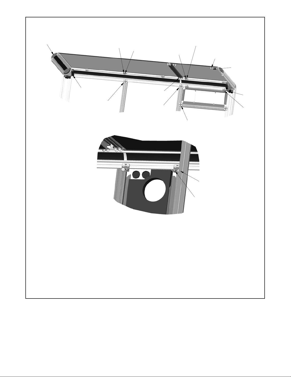
Subject: Sound Shield Kit GM89754-KP2 and UMS Sound Shield Kit
GM90679-KP2
Introduction
The sound shield quiets operation of generator sets
used in marine applications. When installing the sound
shield, follow the installation procedure and observe the
safety precautions listed below.
Read the entire installation procedure before beginning
installation. Perform the steps in the order shown.
Take into consideration the minimum clearance for
vibration and cooling during operation. For sound
shielded units, allow 305 mm (12 inches) minimum
clearance for the left-rear door and front door (intake
and discharge openings).
Safety Precautions
Accidental starting.
Can cause severe injury or death.
Disconnect the battery cables before
working on the generator set.
Remove the negative (--) lead first
when disconnecting the battery.
Reconnect the negative (--) lead last
when reconnecting the battery.
WARNING
Disabling the generator set. Accidental starting can
cause severe injury or death. Before working on the
generator set or equipment connected to the set, disable the
generator set as follows: (1) Press the generator set off/reset
button to shut down the generator set. (2) Disconnect the
power to the battery charger, if equipped. (3) Remove the
battery cables, negative (--) lead first. Reconnect the negative
(--) lead last when reconnecting the battery. Follow these
precautions to prevent the starting of the generator set by the
remote start/stop switch.
Risk of fire.
Can cause severe injury or death.
Do not smoke or permit flames or
sparks near fuels or the fuel system.
WARNING
Servicing the fuel system. A flash fire can cause severe
injury or death. Do not smoke or permit flames or sparks near
the carburetor, fuel line, fuel filter, fuel pump, or other potential
sources of spilled fuels or fuel vapors. Catch fuels in an
approved container when removing the fuel line or carburetor.
Carbon monoxide.
Can cause severe nausea,
fainting, or death.
The exhaust system must be
leakproof and routinely inspected.
WARNING
Operating the generator set. Carbon monoxide can cause
severe nausea, fainting, or death. Be especially careful if
operating the generator set when moored or anchored under
calm conditions because gases may accumulate. If operating
the generator set dockside, moor the craft so that the exhaust
discharges on the lee side (the side sheltered from the wind).
Always be aware of others, making sure your exhaust is
directed away from other boats and buildings.

2TT-1606 5/16
Hazardous voltage.
Can cause severe injury or death.
Operate the generator set only when
all guards and electrical enclosures
areinplace.
Moving parts.
WARNING
Short circuits. Hazardous voltage/current can cause
severe injury or death. Short circuits can cause bodily injury
and/or equipment damage.Do not contact electrical
connections with tools or jewelry while making adjustments or
repairs. Remove all jewelry before servicing the equipment.
Installation Procedure
See Figure 17 for the installed kit illustrations. Refer to
the generator set operation or service manual for items
not shown.
Note: Apply pipe sealant to the male threads of all pipe
fittings before installation.
1. Remove the generator set from service.
1.1 Press the generator set master control
OFF/RESET button.
1.2 Disconnect the power to the battery charger, if
equipped.
1.3 Disconnect the generator set engine starting
battery, the negative (--) lead first.
Note: Before installing the sound shield,
disconnect and route the battery leads
through the holes provided in the skid.
1.4 Remove the junction box panel(s) as needed to
access the wiring.
1.5 Remove the four controller panel screws.
Note: Clearly mark all disconnected leads from
the controller with tape to simplify
reconnection.
1.6 Disconnect the following controller connectors.
See the corresponding wiring diagram found in
the operation manual for more details on wiring.
DP1 (35-pin) connector
DP2 (14-pin) connector
DP3 (8-pin) connector
DP4 Ethernet connector
DAny other external leads to the controller.
1. P3 (8-pin) connector
2. P2 (14-pin) connector
3. P1 (35-pin) connector
4. P4 Ethernet connector
12 3
4
GM89493-
Figure 1 Decision-Maker3500 Controller
Connectors

3TT-1606 5/16
1.7 Remove the controller. Save the hardware and
gasket to remount the controller into the sound
shield’s controller panel later in step 11.1.
1.8 Position the generator set onto the sound shield
base (GM89551) and secure the set with 6 bolts
(X-6238-3 or X-6238-11) and 6 washers
(X-25-37). See Figure 2.
For UMS Kit GM90679-KP2 only: Install two
base plates (GM90745) onto sound shield base
(GM89551).
GM89551-B
Top Vi e w o f B a s e
1. Engine end
2. Mounting hole locations
2
1
Figure 2 Sound Shield Base Mounting Position
1.9 Remove the end bracket cover. See Figure 3.
Save the mounting hardware and discard the
cover.
GM79560-
1. End bracket cover
1
Figure 3 End Bracket Cover
1.10 Remove the belt guard by removing the belt guard
brackets and hardware.
2. Construct the framework.
GM89754-A
1. Rails (GM89770 qty. 4)
2. Internal rail (GM89773), bolts (X-6224-20 qty. 2), washers
(X-25-37 qty. 2), and nuts (X-6210-7 qty. 2)
3. Mounting bracket (GM86091), bolts (X-6224-20 qty. 4), and
nuts (X-6210-7 qty. 4) on each end of rail (GM87544). See
Figure 13.
4. Upper bulkhead (GM89859)
5. Internal rails (GM89774 qty. 2), mounting brackets
(GM86091 qty. 2), bolts (X-6224-20 qty. 6), and nuts
(X-6210-7 qty. 6) on the top of each rail. See Figure 13.
6. Extrusion mounting bracket (GM85876 qty. 4).
See Figure 6 for more detail.
7. LH bulkhead (GM89861)
8. Internal rails (GM89774 qty. 2), mounting bracket
(GM86091), bolts (X-6224-20 qty. 4), and nuts (X-6210-7
qty. 4) on the top of each rail. See Figure 13.
9. RH bulkhead (GM89860)
10. Corner extrusion mounting brackets (GM85875 qty. 4).
See Figure 5 for more detail.
11. Internal rail (GM89772), mounting brackets (GM86091
qty. 2), bolts (X-6224-20 qty. 8), and nuts (X-6210-7 qty. 8).
See Figure 13.
1
1
1
2
3
3
4
5
6
7
8
9
10
11
Figure 4 Sound Shield Framework Installation
2.1 Cut foam (GM87549 or GM88912) to length and
insert into the four rails (GM89770). Save
remaining foam for later.
2.2 Secure the rails (GM89770 qty. 4) to each corner
using the mounting bracket and hardware
identified in Figure 5.

4TT-1606 5/16
2.3 Position the internal rails (GM89774 qty. 4) at the
location shown in Figure 4 using the mounting
bracket and hardware identified in Figure 6.
Nonservice-side internal rails (GM89774 qty.
2): Position a mounting bracket (GM86091) to the
top of each internal rail using three bolts
(X-6224-20) and three nuts (X-6210-7) per
bracket. See Figure 13 for more detail.
Service-side internal rails (GM89774 qty. 2):
Position a mounting bracket (GM86091) to the top
of the internal rail using four bolts (X-6224-20) and
four nuts (X-6210-7) per bracket. See Figure 13
for more detail.
Note: Do not final tighten at this time.
GM86396A-
1. Bolt (X-6238-3 or X-6238-11 qty. 4) and washer (X-25-37
qty. 4)
2. Bolt (X-6224-20 qty. 8), nut (X-6210-7 qty. 8), and washer
(X-25-37 qty. 8)
3. Corner extrusion mounting bracket (GM85875 qty. 4)
1
2
3
Figure 5 Corner Extrusion Mounting Bracket
Installation (Corner Rails to Base, 4 Places)
GM86396A-
1. Extrusion mounting bracket (GM85876 qty. 4)
2. Bolt (X-6224-20 qty. 8), nut (X-6210-7 qty. 8), and washer
(X-25-37 qty. 8)
3. Bolt (X-6238-3 or X-6238-11 qty. 8) and washer (X-25-37
qty. 8)
1
2
3
Figure 6 Extrusion Mounting Bracket Installation
(Rails to Base, 4 Places)
2.4 Position the LH and RH bulkheads (GM89860 and
GM89861) as shown in Figure 4 (items 7 and 9).
Secure the bottom of the bulkheads to the existing
skid using a screw (M933-06020-60), washer
(X-25-40) and nut (M6923-06-80) for each
bulkhead.
Secure the sides of the bulkheads to the two
internal rails using a bolt (X-6224-20), washer
(X-25-37), and nut (X-6210-7) for each bulkhead.
2.5 Position the upper bulkhead (GM89859) as
shown in Figure 4 (item 4).
Secure the bottom of the upper bulkhead to the LH
and RH bulkheads using two screws
(M933-06012-60) and two washers (X-25-40) for
each bulkhead.
Secure the sides of the upper bulkhead to the
internal rails using a bolt (X-6224-20), washer
(X-25-37), and nut (X-6210-7) for each side rail.

5TT-1606 5/16
2.6 Position the internal rail (GM89773) as shown in
Figure 4 (item 2).
Secure the internal rail to the upper bulkhead panel
using two bolts (X-6224-20), two washers
(X-25-37), and two nuts (X-6210-7).
On each end of the internal rail, secure a mounting
bracket (GM86091) using four bolts (X-6224-20)
and four nuts (X-6210-7) per bracket. See
Figure 13 for more detail.
2.7 Position the internal rail (GM89772) as shown in
Figure 4 (item 11).
Secure the internal rail to the corner rail using a
mounting bracket (GM86091), four bolts
(X-6224-20) and four nuts (X-6210-7). See
Figure 13 for more detail.
Secure the other end of the internal rail to the rail
using a mounting bracket (GM86091), four bolts
(X-6224-20) and four nuts (X-6210-7). See
Figure 13 for more detail.
Note: Do not final tighten at this time.
3. Attach the foam and seal on bulkhead.
DAttach the foam and seal to the bulkhead as shown
in Figure 7 for standard sound shield kit or Figure 8
for UMS sound shield Kit.
GM89754-A
1. Foam (GM87548 qty. 2)
2. Foam (GM89778-18)
3. Foam (GM89778-22)
4. Seal (X-6422-39)
5. Foam (GM89778-21)
6. Foam (GM89778-19)
3
64
1
2
5
Figure 7 Foam and Seal Installation for Standard
Sound Shield Kit GM89754-KP2
Follow below method to attach foam pieces for
the UMS sound shield kit:
3.1 Apply adhesive (GM96475) to the foam pieces
shown in Figure 8.
3.2 Stick the insulating hanger stud (GM96473) onto
the adhesive at equal distances.
3.3 Install the foam piece and allows the stud to
protrude through foam piece.
3.4 Install a washer (GM96474) and cap (GM55130)
over the protruding stud.
GM90679-C
1. Foam (GM88911 qty. 2)
2. Foam (GM89803-24)
3. Foam (GM89803-29)
4. Seal (GM89803-26)
5. Seal (X-6422-39)
6. Foam (GM89803-27)
7. Foam (GM89803-25)
8. Foam (GM89803-28)
4
7
6
1
2
3
8
5
Figure 8 Foam and Seal Installation for UMS Sound
Shield Kit GM90679-KP2

6TT-1606 5/16
4. Connect the fuel lines.
4.1 Connect the fuel-inlet line (GM91721) to the fuel
inlet on the engine.
4.2 Remove the fuel fitting from the fuel-return
connection point (nonservice side of the unit).
4.3 Connect the fuel-return line (GM91721) to the
fuel-return connection point.
4.4 Bleed the air from the fuel system according to the
procedure provided in the engine operation
manual.
5. Connect the seawater hose.
5.1 Connect the seawater hose (X-6014-38) to the
seawater inlet on the engine and secure with a
hose clamp (X-426-16).
GM89754-A
1. Flex fuel line (GM91721). Attach to fuel return on engine.
2. Flex fuel line (GM91721). Attach to fuel inlet on engine.
3. Hose (X-6014-38) and hose clamps (X-426-16 qty. 2).
Attach to seawater inlet on engine.
1
23
Figure 9 Internal Connections
5.2 Secure the seawater inlet hose with engine
mounting bracket using a clamp (X-672-33),
screw (M933-06025-60), washer (X-25-40), and
nut (M6923-06-80). See Figure 10.
1GM89754-A
1. Clamp (X-672-33), washer (X-25-40), screw
(M933-06025-60), and nut (M6923-06-80)
Figure 10 Seawater Inlet Clamp Location

7TT-1606 5/16
6. Install the bulkhead connection panel.
6.1 Connect the fuel-inlet line to the fuel-inlet opening
on the bulkhead connection panel.
6.2 Connect the fuel-return line to the fuel-return
opening on the bulkhead connection panel.
6.3 Connect the seawater hose to the seawater
connection on the bulkhead connection panel and
secure with a hose clamp (X-426-16).
6.4 Secure the bulkhead connection panel (GM89753
or GM90715) to the corner rails (GM89770) using
brackets (GM86091 qty. 2), bolts (X-6224-20
qty. 4), and nuts (X-6210-7 qty. 4). See Figure 11.
1
1. Brackets (GM86091 qty. 2), bolts (X-6224-20 qty. 4), and
nuts (X-6210-7 qty. 4)
2. Bulkhead connection panel (GM89753 or GM90715)
GM889754-A
2
1
Figure 11 Secure Bulkhead Connection Panel to
Corner Rails
7. Top Rails and Bracket Installation
2
GM89754-A
1. Rail (GM89769 qty. 2). See Figure 13 for bracket location.
2. Rail (GM89771 qty. 2)
3. Corner (GM86035 qty. 4) and screw (X-67-141 qty. 24)
1
3
1
Figure 12 Top Rail and Bracket Installation
7.1 Cut foam (GM87549 or GM88912) to length and
insert into the rails (GM89769 qty.2 and GM89771
qty. 2). See Figure 13.
7.2 Position the rails (GM89769 qty. 2 and GM89771
qty. 2) as shown in Figure 12.
7.3 Attach the brackets (GM86091 qty. 5) to the
service side rail (GM89771) using the hardware
specified at the locations shown in Figure 13.
7.4 Attach the brackets (GM86091 qty. 4) using the
hardware specified at the locations shown in
Figure 13.
7.5 Secure the corners (GM86035 qty. 4) to the rails
as shown in Figure 12 using six screws
(X-67-141) per corner.
7.6 Position the corner foam (GM87547 or GM88910)
as shown in Figure 13. Install three foam pieces
per corner.

8TT-1606 5/16
GM89754-A
1. Brackets (GM86091 qty. 3), bolts (X-6224-20 qty. 6), and nuts
(X-6210-7 qty. 6)
2. Brackets (GM86091 qty. 2), bolts (X-6224-20 qty. 4), and nuts
(X-6210-7 qty. 4)
3. Brackets (GM86091 qty. 2), bolts (X-6224-20 qty. 8), and nuts
(X-6210-7 qty. 8)
4. Bracket (GM86091), bolts (X-6224-20 qty. 4), and nuts
(X-6210-7 qty. 4)
5. Brackets (GM86091 qty. 2), bolts (X-6224-20 qty. 6), and nuts
(X-6210-7 qty. 6)
6. Wing nuts (X-276-9 qty. 3) installed when installing engine
roof.
7. Wing nuts (X-276-9 qty. 2) installed when installing alternator
roof.
8. Wing nuts (X-276-9 qty. 2) installed when installing controller
panel.
9. Wing nuts (X-276-9 qty. 2) installed when installing exhaust
panel.
10. Foam (GM87549 or GM88912). Insert foam into all rails. Cut
to fit.
11. Corner foam (GM87547 or GM88910 qty. 12). Install three
per corner.
16
10
7
11
5
3
7
8
9
2
2
2
4
3
4
Figure 13 Bracket Location/Installation

9TT-1606 5/16
8. Corner Cover Installation
1
GM89754-A
1. Corner cover (GM86036 qty. 4) and pan head machined
screws (M965A-06020-20 qty. 12)
Figure 14 Corner Covers
8.1 Position the corner covers (GM86036 qty. 4) as
shown in Figure 14 using 3 pan head machined
screws (M965A-06020-20) per corner cover.
9. Install the roofs.
1
GM89754-A
1. Alternator roof (GM89750 or GM90712)
2. Engine roof (GM89747 or GM90710)
2
Figure 15 Roofs
9.1 Position the alternator roof (GM89750 or
GM90712) and engine roof (GM89747 or
GM90710) onto the sound enclosure as shown in
Figure 15.
Attach the alternator roof to the mounting brackets
in the top rail and secure using four wing nuts
(X-276-9). See Figure 13 for more detail.
Attach the engine roof to the mounting brackets in
the top rail and secure using three wing nuts
(X-276-9). See Figure 13 for more detail.
Note: Final tighten all hardware.

10 TT-1606 5/16
10. Install the remaining panels/doors.
10.1 Align the pins with the holes in the bulkhead
connection panel and install the rear panel
(GM89752 or GM90714) on the alternator end of
the unit. See Figure 16 (item 1).
10.2 Align the pins with the holes in the base and install
the LH alternator panel (GM89751 or GM90713)
on the nonservice, alternator side of the unit. See
Figure 16 (item 2).
10.3 Align the pins with the holes in the base and install
the exhaust panel (GM89746 or GM90709) on the
nonservice side of the unit. See Figure 16 (item
3). Attach the top of the exhaust panel to the
mounting brackets in the top rail and secure using
two wing nuts (X-276-9). See Figure 13 for more
detail.
10.4 Align the pins with the holes in the base and install
the LH panel (GM89745 or GM90708) on the
nonservice side, engine end of the unit. See
Figure 16 (item 4).
10.5 Align the pins with the holes in the base and install
the front panel (GM89744 or GM90707) on the
engine end of the unit. See Figure 16 (item 5).
10.6 Align the pins with the holes in the base and install
the two RH panels (GM89743 or GM90706) to the
service side, engine end of the unit. See
Figure 16 (item 6).
10.7 Align the pins with the holes in the base and install
the RH alternator panel (GM89748 or GM90711)
to the service side, alternator end of the unit. Place
decal (GM93648) on RH alternator panel. See
Figure 16 (item 7).
10.8 Position the controller panel (GM89749) as
shown in Figure 16 and attach to the mounting
brackets in the top rail and secure using two wing
nuts (X-276-9). See Figure 13 for more detail.
11. Restore the generator set to service.
11.1 Reconnect the leads that were disconnected in
step 1.6. Position the controller into the controller
panel and secure using the existing hardware and
gasket(removedinstep1.7).
11.2 Check that the generator set is OFF.
11.3 Reconnect the generator set engine starting
battery, the negative (--) lead last.

11TT-1606 5/16
GM89754-A
1. Rear panel (GM89752 or GM90714)
2. LH alternator panel (GM89751 or GM90713)
3. Exhaust panel (GM89746 or GM90709)
4. LH panel (GM89745 or GM90708)
5. Front panel (GM89744 or GM90707)
6. RH panel (GM89743 or GM90706)
7. RH alternator panel (GM89748 or GM90711)
8. Controller panel (GM89749)
1
23
4
5
6
6
7
8
Figure 16 Panel Identification

12 TT-1606 5/16
1. Controller panel (GM89749)
2. Alternator roof (GM89750 or GM90712)
3. Engine roof (GM89747 or GM90710)
4. Corner cover (GM86036 qty. 4) and screws
(M965A-06020-20 qty. 12)
5. Alternator panel (RH) (GM89748 or GM90711)
6. Panel (RH) (GM89743 or GM90706 qty. 2)
7. Base (GM89551)
8. Front panel (GM89744 or GM90707)
9. Panel (LH) (GM89745 or GM90708)
10. Exhaust panel (GM89746 or GM90709)
11. Alternator panel (LH) (GM89751 or GM90713)
12. Rear Panel (GM89752 or GM90714)
13. Bulkhead connection panel (GM89753 or GM90715)
GM89754-A
1
2
3
4
5
6
78
9
10
11 12
13
Figure 17 Sound Shield

13TT-1606 5/16
Sound Shield Kit
Kit: GM89754-KP2
Qty. Description Part Number
4Bracket, corner extrusion mounting GM85875
4Bracket, extrusion mounting GM85876
1Base (86.8 x 38.2 in.) GM89551
4Corner, sound shield GM86035
4Cover, sound shield corner GM86036
1Bulkhead, upper sound shield
(36.5 x 26.1 in.) GM89859
1Bulkhead, sound shield (RH)
(10.4 x 7.7 in.) GM89860
1Bulkhead, sound shield (LH)
(12.9 x 7.7 in.) GM89861
2Rail, sound shield (30 in.) GM89769
4Rail, sound shield (37 in.) GM89770
2Rail, sound shield (78.6 in.) GM89771
1Rail, internal sound shield (22.6
in.) GM89772
1Rail, internal sound shield (30 in.) GM89773
4Rail, internal sound shield (37 in.) GM89774
19 Bracket, sound shield
(1.7 x 1.7 in.) GM86091
2Panel (RH) (27.8 x 38 in.) GM89743
1Panel (front) (23.6 x 38 in.) GM89744
1Panel (LH) (42.2 x 38 in.) GM89745
1Roof, engine (55.7 x 31.8 in.) GM89747
1Panel, alternator (RH)
(24.5 x 28 in.) GM89748
1Panel, controller (24.5 x 10 in.) GM89749
1Roof, alternator (24.5 x 31.8 in.) GM89750
1Panel, rear (31.5 x 31.8 in.) GM89752
2Fuel line, flex. (78 in.) GM91721
1Panel, exhaust (13.4 x 32.2 in.) GM89746
1Panel, bulkhead connection
(6.4 x 31.8 in.) GM89753
1Panel, alternator (LH)
(24.5 x 38 in.) GM89751
Qty. Description Part Number
12 Screw, pan head mach.
(M6 x 20 mm) M965A-06020-20
40 Washer, plain
(0.406 ID x 0.812 in. OD) X-25-37
24 Screw, hex washer, thread-forming X-67-141
11 Nut, wing (1/4-20) X-276-9
2Clamp, hose (1.81/2.75 in.) X-426-16
1Hose ( 2 in. ID x 100 in.) X-6014-38
74 Nut, flange spiralock (5/16-18) X-6210-7
74 Bolt, carriage (5/16-18 x 0.75 in.) X-6224-20
18 Bolt, hex cap (3/8-16 x 0.875 in.) X-6238-3
3Nut, hex (6 mm) M6923-06-80
4Screw, hex cap (M6 x 12 mm) M933-06012-60
2Screw, hex cap (M6 x 20 mm) M933-06020-60
1Screw, hex cap (M6 x 25 mm) M933-06025-60
7Washer, plain
(0.281 ID x 0.625 in. OD) X-25-40
1Seal, push-on trim X-6422-39
1Clamp (2.62 in.) X-672-33
1Foam (36.4 x 26 in.) GM89778-18
1Foam (8.66 in.) GM89778-19
1Foam (8.66 in.) GM89778-22
1Foam (34.3 x 5.75 in.) GM89778-21
12 Foam (3.6 x 3.6 in.) GM87547
2Foam (5 x 5 in.) GM87548
6Foam (54 x 4.5 in.) GM87549
1Decal GM93648

14 TT-1606 5/16
UMS Sound Shield Kit
Kit: GM90679-KP2
Qty. Description Part Number
4Bracket, corner extrusion mounting GM85875
4Bracket, extrusion mounting GM85876
1Base (86.8 x 38.2 in.) GM89551
4Corner, sound shield GM86035
4Cover, sound shield corner GM86036
1Bulkhead, upper sound shield
(36.5 x 26.1 in.) GM89859
1Bulkhead, sound shield (RH)
(10.4 x 7.7 in.) GM89860
1Bulkhead, sound shield (LH)
(12.9 x 7.7 in.) GM89861
2Rail, sound shield (30 in.) GM89769
4Rail, sound shield (37 in.) GM89770
2Rail, sound shield (78.6 in.) GM89771
1Rail, internal sound shield (22.6
in.) GM89772
1Rail, internal sound shield (30 in.) GM89773
4Rail, internal sound shield (37 in.) GM89774
19 Bracket, sound shield
(1.7 x 1.7 in.) GM86091
2Panel (RH) (27.8 x 38 in.) GM90706
1Panel (front) (23.6 x 38 in.) GM90707
1Panel (LH) (42.2 x 38 in.) GM90708
1Roof, engine (55.7 x 31.8 in.) GM90710
1Panel, alternator (RH)
(24.5 x 28 in.) GM90711
1Panel, controller (24.5 x 10 in.) GM89749
1Roof, alternator (24.5 x 31.8 in.) GM90712
1Panel, rear (31.5 x 31.8 in.) GM90714
2Fuel line, flex. (78 in.) GM91721
1Panel, exhaust (13.4 x 32.2 in.) GM90709
1Panel, bulkhead connection
(6.4 x 31.8 in.) GM90715
1Panel, alternator (LH)
(24.5 x 38 in.) GM90713
Qty. Description Part Number
12 Screw, pan head mach.
(M6 x 20 mm) M965A-06020-20
40 Washer, plain
(0.406 ID x 0.812 in. OD) X-25-37
24 Screw, hex washer, thread-forming X-67-141
11 Nut, wing (1/4-20) X-276-9
2Clamp, hose (1.81/2.75 in.) X-426-16
1Hose ( 2 in. ID x 8.33 in.) X-6014-38
74 Nut, flange spiralock (5/16-18) X-6210-7
74 Bolt, carriage (5/16-18 x 0.75 in.) X-6224-20
18 Bolt, hex cap (3/8-16 x 1 in.) X-6238-11
3Nut, hex (6 mm) M6923-06-80
4Screw, hex cap (M6 x 12 mm) M933-06012-60
2Screw, hex cap (M6 x 20 mm) M933-06020-60
1Screw, hex cap (M6 x 25 mm) M933-06025-60
7Washer, plain
(0.281 ID x 0.625 in. OD) X-25-40
1Seal, push-on trim X-6422-39
1Clamp (2.62 in.) X-672-33
1Foam (15.8 x 36.4 in.) GM89803-24
1Foam (8.7 x 10 in.) GM89803-25
1Foam (8.7 x 12.6 in.) GM89803-26
1Foam (5.7 x 34.3 in.) GM89803-27
1Foam (10.1 x 13.2 in.) GM89803-28
1Foam (10.1 x 10 in.) GM89803-29
12 Foam (3.6 x 3.6 in.) GM88910
2Foam (5 x 5 in.) GM88911
6Foam (48 x 4.5 in.) GM88912
2Base plate, sound shield GM90745
1Decal GM93648
75 Insulation hanger stud GM96473
75 Washer, insulation hanger stud GM96474
1Adhesive GM96475
75 Cap, EPSI masking GM55130

15TT-1606 5/16
Notes

16 TT-1606 5/16
KOHLER CO., Kohler, Wisconsin 53044 USA
Phone 920-457-4441, Fax 920-459-1646
For the nearest sales and service outlet in the
US and Canada, phone 1-800-544-2444
KOHLERPower.com
Kohler Power Systems
Asia Pacific Headquarters
7 Jurong Pier Road
Singapore 619159
Phone (65) 6264-6422, Fax (65) 6264-6455
Availability is subject to change without notice. Kohler Co. reserves the
right to change the design or specifications without notice and without any
obligation or liability whatsoever. Contact your local Kohlerrgenerator
set distributor for availability.
2014 and 2016 by Kohler Co. All rights reserved.
This manual suits for next models
3
Table of contents
Other Kohler Marine Equipment manuals

Kohler
Kohler GM89754-KP1 User manual

Kohler
Kohler GM31994-KP1 User manual

Kohler
Kohler 6EKOD User manual

Kohler
Kohler 6EOD Instruction Manual

Kohler
Kohler 6EKOD User manual

Kohler
Kohler 5EOZ User manual

Kohler
Kohler GM93516-KP1 User manual

Kohler
Kohler 4EOZ Assembly instructions

Kohler
Kohler 40EFOZ User manual

Kohler
Kohler 13EKOZD User manual