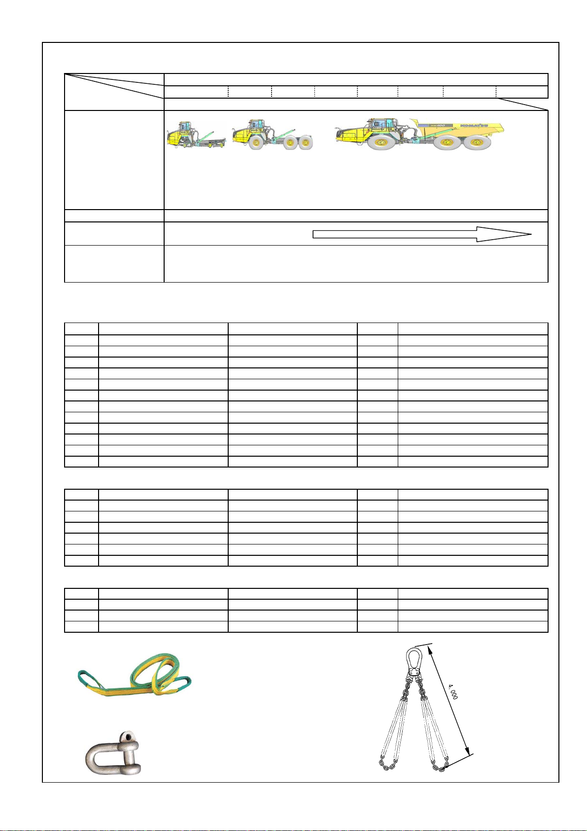
3. Assembly procedure, necessary equipments, and schedule
Day
Hour 1 23456 7 8
(1) Positioning chassis (3) Mounting body (4) Adjusting each parts
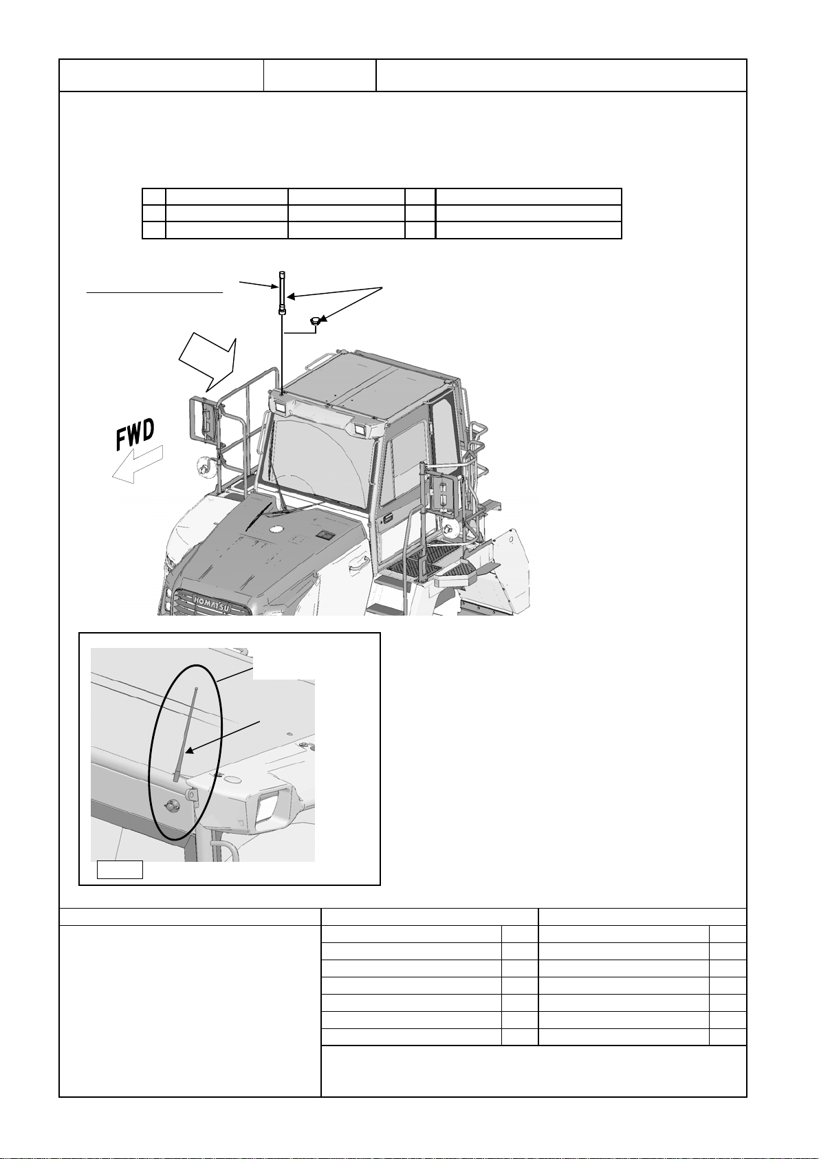
(2) Installing tires Mirror and antenna
(5) Inspection
Meeting before work Completion of assembly
Unloading
Starting assembly
4. Necessary tools and equipments
(1) Necessary tools
No. Q'ty
1 1 set
21
31
4 1 set
51
61
7 1 set
81
91
10 1 set
11 1
12 1
(2) Necessary equipments
No. Q'ty
12
21
31
41
52
612
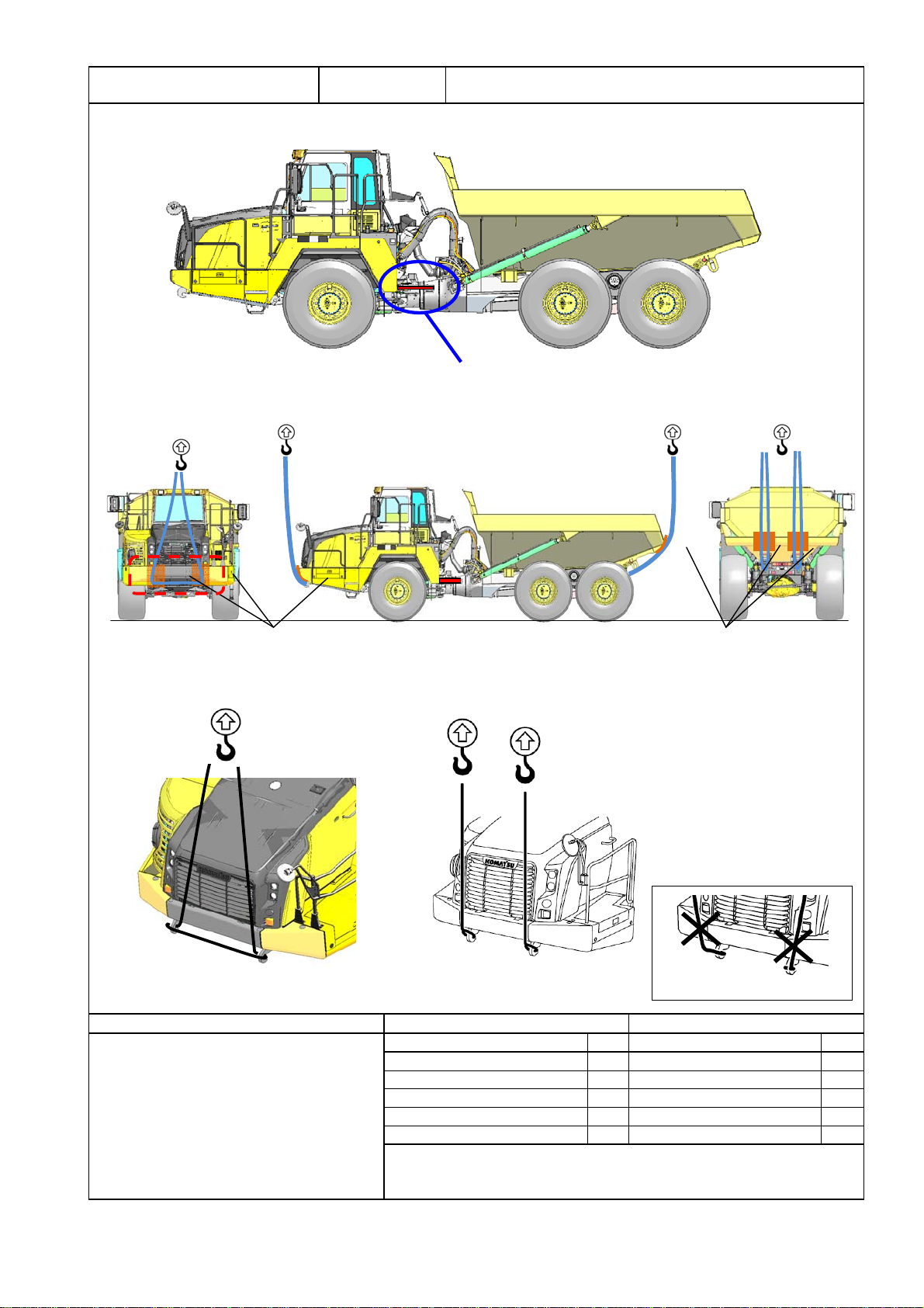
(3) Necessary lifting tools
No. Q'ty
14
21
34
Lifting tire L: 4,000 Chain diamete φ6.3 For tire chassis
Shackle Withstand load :Min. 1 ton For connecting body and sling tools
Equipment name Specifications Remarks
Nylon sling For 15 ton xL: 4,000 For slinging protector
Steel plate t 9 × 1,219 × 2,438 For setting bare machine in place
Wood block 400 × 400 × 900 For setting bare machine in place
Compressor Capacity: Min. 32 ℓFor impact wrench
Stepladder (Work stand) 4 steps (About 1.5m) For work
Crane Min. 25 ton For slinging protector
Forklift Min. 2 ton For mounting tire
Bar For adjustment of holes when mounting tire
Equipment name Specifications Remarks
Suspension gas pouring tool 7926-10-1000 For adjusting suspension pressure
Touch-up paint spray can
Impact wrench GT-S22m or equivalent For mounting tire
Torque wrench Can be measured 927 Nm { 94.5 kgm} For mounting tire
Number of workers
Socket
SpecificationsTool name
Ring wrench
Socket
Remarks
Standard tools (Wrench set)
36 mm (Entry corner 25.4)
2
1st day
Assembly Procedure No.
Assembly unit
No.0010-0900
Remarks
For tightening each place
For mounting tire
For tightening each placeStandard tools ( Socket set )
Paint spray can Clear For touch-up bolt head
Impact wrench For tightening each place
Extension bar Entry corner 25.4 × L:160 For mounting tire
Natural yellow For touch-up body and hoist cylinder
Grease gun For each parts grease-up
Length : 4,000 mm
Specification load : 15 ton
Chain diameter
φ 6.3 mm
Specification load :
3.20 ton
21
3


 Operator's manual")