manuals.online logo
Brands
  1. Home
  2. •
  3. Brands
  4. •
  5. Konica Minolta
  6. •
  7. Printer Accessories
  8. •
  9. Konica Minolta PK-511 User manual

Konica Minolta PK-511 User manual

E-1
INSTALLATION MANUAL
A04E955034
PK-511 Punch Kit
I. Accessory parts
II. Preliminary Preparation
1. Turn the machine’s Sub and Main switches OFF,
and unplug the power cord.
2. Remove the finisher if there is one mounted to
the machine.
III. Installation procedures
1. Open the front door of the Finisher.
2. Remove the control board cover. (1 screw)
3. Remove the guide plate. (2 screws)
4. Insert the two of the control board support/1 into
the back side, and insert two into the front side.
Insert the two of the control board support/2 into
the central area of the front side.
No. Name Shape Q’ty
1. Punch Kit
15KJIXC001SA
1
2. Punch waste
box
15KNIXC002SA
1
3. Control board
A04EIXC001SA
1
4. Control board
support /1 15KNIXC004SA
4
5. Control board
support /2 15KJIXC003SA
2
6. Sensor
assembly wire
bundle
15KJIXC004SA
1
7. TP screw
M4x6 4
8. TP screw
M3x6 2
9. Installation
manual
1
Control board
cover
Guide plate
15KNIXE001SB
15KJIXE001SA
Control board
support /1
Control board
support /1
Control board
support /2
Applied Machines: FS-520/FS-607
E-2
5. Making sure the direction is correct, install the
control board on the control board supports.
Note:
When installing the control board, mount it so that
the notched portion of the control board faces the
front.
6. Pass the Punch kit connectors of the sensor assem-
bly wire bundle through the hole and attach the wire
bundle to the eight wire saddles.
Note:
• Let the control board side connectors hang down
to the bottom.
• Let the first wire bundle of the Punch kit con-
nectors hang out from the hole, as shown in the
figure.
7. Temporarily tighten the screw (TP screw M3x6: 1
pc.) on the back side of the finisher. Position the
sensor on the sensor assembly wire bundle with
the projection then fasten with the temporarily
tightened screw.
Note:
Make sure pass the sensor assembly wire bundle
on the right side of the sensor.
8. Connect the sensor assembly wire bundle connec-
tors (4 locations) to the control board connectors.
9. Attach the wire bundle to the four wire saddles.
A04EIXE001SA
Notched portion
Control board
15KJIXE003SA
Bundled
portion
Wire saddles
Wire saddles
15KJIXE004SB
TP screw M3x6
Sensor assembly wire bundle
Sensor
A04EIXE002SA
Connectors
Connector
A04EIXE003SA
Wire saddles
E-3
10. Remove the Punch kit cover. (TP screw M3x6: 2
pcs.)
11. Remove the locking screw of the punch kit
attached to the end of the red tag.
12. Install the Punch kit.
(1) Make sure the guide pin on the inner side of
the Punch kit go into the guide hole in the Fin-
isher.
Note:
Put the Punch kit wire bundle in the finisher before
inserting the Punch Kit.
(2) Align the markings of the punch kit to the cen-
ter and secure. (TP screw M4x6: 4 pcs.)
Make sure to open and close the conveyance
guide plate/1 once so that the PET at the entrance
of the punch kit return to normal position.
(3) Connect the two Punch kit connectors to the
Punch kit, and attach the wire bundle to the
two mini wire saddles.
Note:
Arrange the wire bundle at a proper distance from
the gear.
(4) Connect the Punch kit wire bundle to three connec-
tors on the control board as shown in the figure.
15KJIXE007SA
TPscrews M3x6
15KJIXE008SA
Red tag
Locking screw
A04EIXE008SA
PK-511
For PK-511
TPscrews M4x6
15KJIXE011SB
Markings
TPscrews M4x6
Conveyance guide plate/1
15KJIXE012SB
Punch kit connectors
Mini wire saddles
A04EIXE004SA
Connectors
E-4
(5) Attach the Punch kit wire bundle to the four wire
saddles.
13. Align the control board cover with the grooves
and slide in the board, then secure. (1 screw)
14. Install the Punch waste box, and close the fin-
isher’s front door.
15. Install the finisher to the machine.
Note:
• Check that the machine installation plate/ lower
(Finisher accessory parts) hook is securely set
on the finisher when installing the finisher to the
machine.
• Refer to the finisher installation manual for details
on installing the finisher to the machine.
16. Software DipSW setting.
17. Paper edge detect sensor adjustment.
A04EIXE005SA
Wire saddles
15KJIXE017SA
Control board cover
15KJIXE018SA
Punch waste box
Step
1. Plug the power cord into the outlet and turn
ON the Main power switch.
2. Enter Service mode.
Note:
Refer to procedures in the Service Manual to
enter into the Service Mode.
3. [Service Mode menu screen]
Touch “System Setting”.
4. Touch “Software SW Setting”.
5. Set 22-1-0(OFF), 22-2-0(OFF), 23-7-0(OFF)
and touch “Return”.
6. Turn OFF the Sub power switch and Main
power switch.
Step
1. Turn ON the Main power switch.
2. Enter Service mode.
Note:
Refer to procedures in the Service Manual to
enter into the Service Mode.
3. [Service Mode Menu screen]
Touch “Finisher Adjustment”.
4. [Finisher Adjustment Menu screen]
Touch “Punch Adjustment”.
5. [Punch Adjustment Menu screen]
Touch “PaperEdgeDetectSensorAdj.”.
6. [Paper Edge Detect Sensor Adjustment screen]
Touch “Start”.
7. When adjustment is done correctly, message
of “Completed” is indicated.
8. Turn OFF the Sub power switch and Main
power switch.
A04EIXE006SA
Machine
Lower view
Finisher
Securelyinstalling
the finisher to the machine.
E-5
18. Adjust the skew of the hole punch position.
(1) Insert a piece of paper into the finisher’s inter-
lock to turn it ON.
(2) Turn ON the Main power switch and Sub power
switch of the machine, and make sample copies
for both the single-side and double-side with
any tray in Punch mode.
(3) Using the paper sample, check the hole posi-
tion gap by folding the paper in half.
(4) If hole position gap is found, loosen the Punch
kit fix screws (TP screw M4x6: 4 pcs.) and move
the punch kit to the left or right to the amount of
the skew.
Note:
When doing so, adjust the gap in the depth direc-
tion according to “Adjusting the vertical punch posi-
tion” on pages 8.
19. Adjust the skew of the hole punch position.
(When PI-502 is installed to the finisher)
(1) Make sample copies from the PI-502 in Punch
mode.
(2) Using the paper sample, check the hole posi-
tion gap by folding the paper in half.
(3) If hole position gap is found, loosen the finisher
guide plate fixing screw and move it to the left
or right to the amount of the skew.
20. Centering adjustment.
Execute for each paper size and tray.
(1) Make sample copies in Punch mode to check
that the punching hole is within the sensor area
when the hole is punched. (For all trays)
(2) If punching position gap is found, adjust the cen-
tering of the tray. (Refer to the Service manual)
15KJIXE019SA
Paper
15KJIXE020SB
Output samples
TPscrews M4x6
TPscrewM4x6
When wide in back When wide in front
15KJIXE021SB
Guide plate
fixing screw
Finisher/front
Output samples
When wide in backWhen wide in front
15KJIXE022SA
Punching position
should be in this range
Sensor
E-6
21. Install the Punch kit cover. (TP screw M3x6: 3 pcs.)
Note:
When installing the Punch kit cover, be careful not
to get the wire bundles caught in it.
22. Pull out the paper nipped by the interlock and
close the finisher’s front door.
Adjusting PI-502 centering
1. Preliminary preparations before adjustment
(1) Place paper in the upper and lower trays of the
PI-502, and make sample copies using the
cover sheet in Punch mode. Check that the
punching hole is within the sensor area when
the hole is punched.
(For upper and lower trays)
* See the figure for item 20 on page E-5.
(2) If there is a gap, execute the next page proce-
dure to adjust it.
2. Adjustment procedures
Step
1. Release the hook and remove the adjustment
cover of the side guide board/back.
15KJIXE023SA
TPscrews M3x6
Punch kit cover
15KNIXE012SA
Adjustment cover
Hook
Side guide board
/back
2. For the lower tray, remove the 2 side guide
board/back mounting screws and slide it to the
right to remove the side guide board/back.
3. Loosen the 2 adjustment screws on the side
guide board/back, and slide the side guide
board/2 to twice the distance of the punch hole
gap. (Example: if holes are centered 1.5mm to
the back, slide the board back 3mm.)
Gradation: 2mm.
4. Tighten the 2 adjustment screws securely to
fix side guide board/2.
5. Install the side guide board/back in the lower
tray.
Note:
When tightening the 2 mounting screws, make
sure that screw torque doesn’t exceed 5kg • cm.
6. Place paper in the tray and adjust the side
guides. Make sure that the side guide board/
back is parallel to the paper.
7. Repeat steps 2 to 6 until punch hole centering
error is eliminated.
8. Install the adjustment cover on the side guide
board/back.
Step
15KNIXE013SA
Side guide board
/back
Mounting
screws
15KNIXE014SA
Adjustment
screws
Side guide board/2
E-7
IV. Adjustment
Implement adjustments if parameters do not have
appropriate values.
Adjusting the horizontal punch position
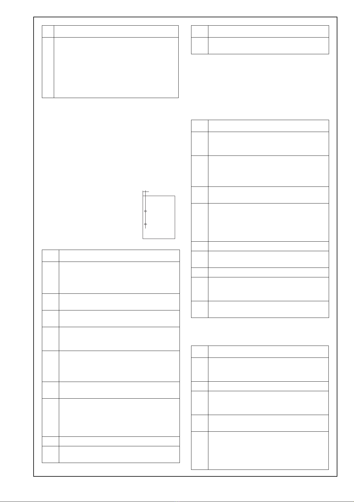
1. Standard values
It is possible to adjust up to ± 5 mm from the stan-
dard value (the distance between the edge of the
paper and the center of the hole).
Standard hole positions A = 10.5
2. Adjustment procedures
Adjusting the punch registration
Note:
This adjustment is performed when the punch hole
positions are skewed.
1. Adjustment for machine punch registration amount
• Main Body/reverse
• Main Body/ADU
2. Adjustment for PI-502 punch registration amount
• PI1 Tray
• PI2 Tray
9. Place A4 or 8.5x11 paper by short edge feed-
ing in the cover sheet tray, and adjust the
cover sheet tray size in [Service Mode].
Note:
If the side guide board/back slides too much,
first adjust the cover sheet tray size in [Ser-
vice Mode] as described in step 9, and then
start from step 2 again.
Step
1. Enter Service mode.
Note:
Refer to procedures in the Service Manual
to enter into the Service Mode.
2. [Service Mode Menu screen]
Touch “Finisher Adjustment”.
3. [Finisher Adjustment Menu screen]
Touch “Punch Adjustment”.
4. [Punch Adjustment Menu screen]
Touch “Horizontal Position Adj.”.
Select “PI tray” or “Main tray”.
5. Touch “COPY” to display the Copy Screen.
Load the paper on a PI or machine tray, and
make a sample copy. Check the punch hori-
zontal position of the sample copy.
6. Touch “SERVICE” to return to [Punch Adjust-
ment <Horizontal position adjustment> screen].
7. If the punch horizontal position is not appro-
priate, use the numerical keys on the screen
to enter adjusting values (appropriate val-
ues), and touch “<<SET”.
(Setting range: -50 to +50 1 step = 0.1mm)
8. Make another sample copy.
9. Repeat steps 5 to 8 until the punch horizon-
tal position is appropriate.
Step
A
15KNIXC006S
A
10. Touch “Return” to return to the [Punch Adjust-
ment Menu] screen.
Step
1. [Punch Adjustment Menu screen]
Touch “Registration Adjustment”. Check that
“Main Body/reverse” is highlighted.
2. Touch “COPY” to display the Copy Screen.
Load the paper on the tray, and make a sam-
ple copy. Check the punch registration of the
sample copy.
3. Touch “SERVICE” to return to [Punch Adjust-
ment <Registration adjustment> screen].
4. If the punch registration is not appropriate,
use the numerical keys on the screen to
enter adjusting values (appropriate values),
and touch “<<SET”.
(Setting range: -20 to +20 1 step = 0.8mm)
5. Make another sample copy.
6. Repeat steps 2 to 5 until the punch registra-
tion size of Main Body/reverse is appropriate.
7. Touch “Main Body/ADU”.
8. Touch ‘COPY”, make a punch registration
sample copy on the copy screen, and check
the punch registration size.
9. Repeat steps 2 to 5 until the punch registra-
tion size of Main Body/ADU is appropriate.
Step
1. [Punch Adjustment <Registration Adjustment>
screen]
Touch “PI1 Tray”.
2. Place paper in the PI1 tray.
3. Touch ‘COPY”, make a punch registration
sample copy on the copy screen, and check
the punch registration size.
4. Touch “SERVICE” to return to [Punch Adjust-
ment <Registration adjustment> screen].
5. If the punch registration is not appropriate,
use the numerical keys on the screen to
enter adjusting values (appropriate values),
and touch “<<SET”.
(Setting range: -20 to +20 1 step = 0.8mm)
Step
E-8
Adjusting the vertical punch position
1. Standard value
• It is possible to adjust the B dimension of half of
the top and bottom by ±5mm from the standard
value.
• It is not possible to adjust the B value of the dis-
tance between holes.
Standard hole position
2. Adjustment procedure
6. Make another sample copy.
7. Repeat steps 3 to 6 until the punch registra-
tion size of PI1 tray is appropriate.
8. Place paper in the PI2 tray.
9. Repeat steps 3 to 6 until the punch registra-
tion size of PI2 tray is appropriate.
10. Touch “Return” to return to the [Punch Adjust-
ment Menu] screen.
B Top and bottom center gap
80 ± 0.5 Top and bottom B dimension 1/2 ± 1
Step
1. [Punch Adjustment Menu screen]
Touch “Vertical Position Adj.”.
2. Select the paper size to be adjusted.
3. Touch “COPY” to display the Copy Screen.
Load the paper of size to be adjusted on the
tray, make a sample copy. Check the punch
vertical position of the sample copy.
4. Touch “SERVICE” to return to [Punch Adjust-
ment <Vertical position adjustment> screen].
5. If the punch vertical position is not appropri-
ate, use the numerical keys on the screen to
enter adjusting values (appropriate values),
and touch “<<SET”.
(Setting range: -50 to +50 1 step = 0.1mm)
6. Make another sample copy.
7. Repeat steps 3 to 6 until the punch vertical
position is appropriate.
8. Repeat the same operation about other sizes.
Step
B
15KNIXC008S
A

Other Konica Minolta Printer Accessories manuals

Konica Minolta magicolor 2430 DL User manual

Konica Minolta

Konica Minolta magicolor 2430 DL User manual

Konica Minolta WT-513 User manual

Konica Minolta

Konica Minolta WT-513 User manual

Konica Minolta HT-502 User manual

Konica Minolta

Konica Minolta HT-502 User manual

Konica Minolta DF-704 User manual

Konica Minolta

Konica Minolta DF-704 User manual

Konica Minolta AFR-12 Configuration guide

Konica Minolta

Konica Minolta AFR-12 Configuration guide

Konica Minolta HD-524 User manual

Konica Minolta

Konica Minolta HD-524 User manual

Konica Minolta bizhub 223 User manual

Konica Minolta

Konica Minolta bizhub 223 User manual

Konica Minolta DB-209 How to use

Konica Minolta

Konica Minolta DB-209 How to use

Konica Minolta PC-101 User manual

Konica Minolta

Konica Minolta PC-101 User manual

Konica Minolta DK-510 User manual

Konica Minolta

Konica Minolta DK-510 User manual

Konica Minolta PI-506 User manual

Konica Minolta

Konica Minolta PI-506 User manual

Konica Minolta bizhub 361 User manual

Konica Minolta

Konica Minolta bizhub 361 User manual

Konica Minolta AD-509 User manual

Konica Minolta

Konica Minolta AD-509 User manual

Konica Minolta JS-506 User manual

Konica Minolta

Konica Minolta JS-506 User manual

Konica Minolta Image Controller IC-402 User manual

Konica Minolta

Konica Minolta Image Controller IC-402 User manual

Konica Minolta bizhub 223 User manual

Konica Minolta

Konica Minolta bizhub 223 User manual

Konica Minolta Magicolor 5550 Operating and maintenance instructions

Konica Minolta

Konica Minolta Magicolor 5550 Operating and maintenance instructions

Konica Minolta Image Controller IC-205 User manual

Konica Minolta

Konica Minolta Image Controller IC-205 User manual

Konica Minolta Di1611 User manual

Konica Minolta

Konica Minolta Di1611 User manual

Konica Minolta PI-505 User manual

Konica Minolta

Konica Minolta PI-505 User manual

Konica Minolta LU-204 User manual

Konica Minolta

Konica Minolta LU-204 User manual

Konica Minolta PC-410 User manual

Konica Minolta

Konica Minolta PC-410 User manual

Konica Minolta FS-110 User manual

Konica Minolta

Konica Minolta FS-110 User manual

Konica Minolta bizhub C650 Series User manual

Konica Minolta

Konica Minolta bizhub C650 Series User manual

Popular Printer Accessories manuals by other brands

Intermec EasyCoder 601XP installation instructions

Intermec

Intermec EasyCoder 601XP installation instructions

Canon AG1 Service manual

Canon

Canon AG1 Service manual

HP Laserjet,Color Laserjet 2550L install guide

HP

HP Laserjet,Color Laserjet 2550L install guide

MIMAKI OPT-J0501 Operation manual

MIMAKI

MIMAKI OPT-J0501 Operation manual

Muratec MFX-2500 user guide

Muratec

Muratec MFX-2500 user guide

Kyocera DF-420 Service manual

Kyocera

Kyocera DF-420 Service manual

Kodak E2635 Technical data

Kodak

Kodak E2635 Technical data

Canon DADF-M1 Service manual

Canon

Canon DADF-M1 Service manual

Century CSR Series quick start guide

Century

Century CSR Series quick start guide

Seiko Epson B12B819611 quick start guide

Seiko Epson

Seiko Epson B12B819611 quick start guide

Kyocera TASKalfa 650c installation instructions

Kyocera

Kyocera TASKalfa 650c installation instructions

Xerox 497K17750 manual

Xerox

Xerox 497K17750 manual

Symbol 6110 Installation procedures

Symbol

Symbol 6110 Installation procedures

HP LaserJet LJ 5M instructions

HP

HP LaserJet LJ 5M instructions

Kyocera PF-740 Service manual

Kyocera

Kyocera PF-740 Service manual

Roland VS-420 manual

Roland

Roland VS-420 manual

Epson C12C936001 Setup guide

Epson

Epson C12C936001 Setup guide

Epson C83202 user guide

Epson

Epson C83202 user guide

manuals.online logo
manuals.online logoBrands
  • About & Mission
  • Contact us
  • Privacy Policy
  • Terms and Conditions

Copyright 2025 Manuals.Online. All Rights Reserved.