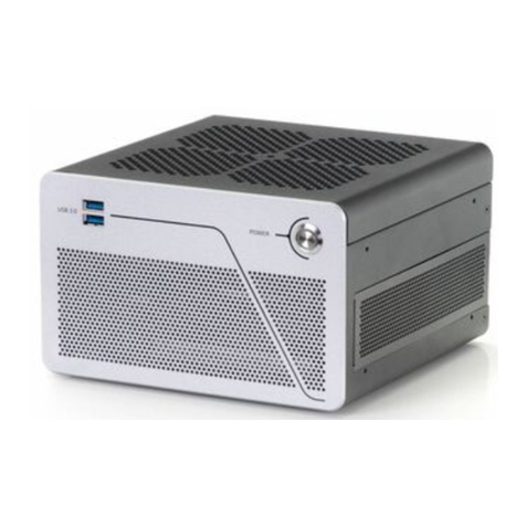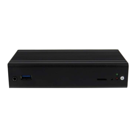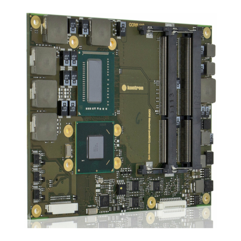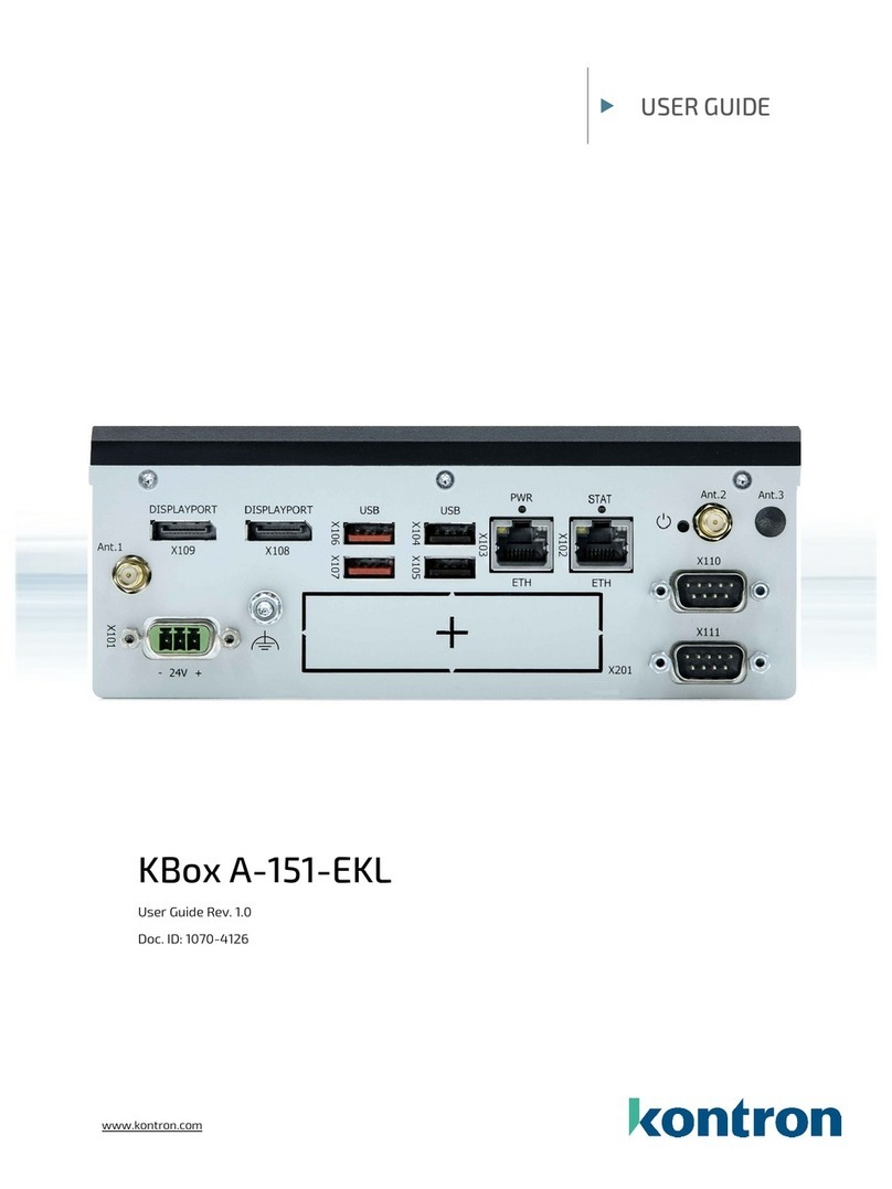
KBox B-201-CFL - User Guide, Rev. 1.0
www.kontron.com // 9
Table of Contents
Symbols.................................................................................................................................................................................................................6
For Your Safety ...................................................................................................................................................................................................7
High Voltage Safety Instructions ..................................................................................................................................................................7
Special Handling and Unpacking Instruction ............................................................................................................................................7
Lithium Battery Precautions.......................................................................................................................................................................... 8
General Instructions on Usage..................................................................................................................................................................... 8
Quality and Environmental Management................................................................................................................................................ 8
Disposal and Recycling.................................................................................................................................................................................... 8
WEEE Compliance.............................................................................................................................................................................................. 8
Table of Contents...............................................................................................................................................................................................9
List of Tables ......................................................................................................................................................................................................11
List of Figures.....................................................................................................................................................................................................11
1/ General Safety Instructions for IT Equipment.........................................................................................................................13
2/ Introduction .........................................................................................................................................................................................16
3/ Scope of Delivery ...............................................................................................................................................................................17
3.1. Packaging.....................................................................................................................................................................................................17
3.2. Type Label and Product Identification...............................................................................................................................................17
4/ Product Overview ..............................................................................................................................................................................18
4.1. Front Side.....................................................................................................................................................................................................19
4.1.1. Front Connectors and Buttons ..........................................................................................................................................................19
4.2. Rear Side ....................................................................................................................................................................................................20
4.2.1. Rear Panel Connectors ........................................................................................................................................................................21
4.3. Left and Right Sides................................................................................................................................................................................24
4.4. Top Cover and Bottom Sides ............................................................................................................................................................... 25
5/ System Extension .............................................................................................................................................................................26
5.1. External Storage.......................................................................................................................................................................................26
5.1.1. 2.5” SSD Drive Bay .................................................................................................................................................................................26
5.2. Internal Expansion ..................................................................................................................................................................................26
5.2.1. mPCIE Socket..........................................................................................................................................................................................26
5.2.2. M.2 Socket .............................................................................................................................................................................................. 27
6/ Accessing Internal Components..................................................................................................................................................28
6.1. Opening and Closing the Chassis........................................................................................................................................................28
6.2. Opening and Closing SSD Drive Bay Cover......................................................................................................................................30
6.2.1. Installing and Removing Externally Accessible 2.5” SSD .........................................................................................................31
6.3. Installing and Removing Internal M.2 SSD......................................................................................................................................32
6.4. Installing and Removing Internal mPCIe Expansion Card.......................................................................................................... 32
7/ Thermal Considerations .................................................................................................................................................................34
7.1. Active Cooling ............................................................................................................................................................................................34
7.2. Minimum System Clearance (Keep out Area) ................................................................................................................................ 35
7.3. Third Party Components ....................................................................................................................................................................... 35
8/ Installation Instructions.................................................................................................................................................................36
8.1. Chassis Feet............................................................................................................................................................................................... 37
8.1.1. Chassis Feet Mount Option ................................................................................................................................................................ 37
8.2. Vertical Stand (Option)..........................................................................................................................................................................38
8.2.1. Vertical Stand Mount Options ..........................................................................................................................................................38
8.3. Mounting Brackets (Option) ................................................................................................................................................................39
