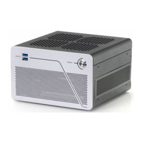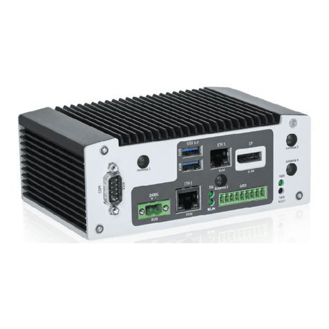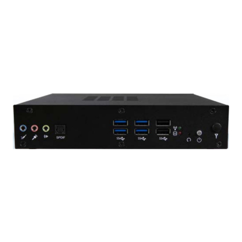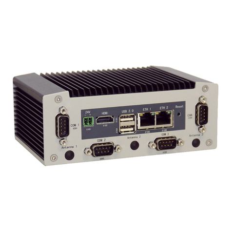
KBox F-220 Series - User Guide, Rev. 1.0
www.kontron.com // 10
4.3.4. GbE............................................................................................................................................................................................................ 25
4.3.5. RS232/422/485 ...................................................................................................................................................................................26
4.3.6. WLAN Antenna Port ............................................................................................................................................................................26
4.4. Internal View............................................................................................................................................................................................. 27
4.4.1. DDR4 SO-DIMM Memory Socket .....................................................................................................................................................28
4.4.2. SATA Power / Data Connector ........................................................................................................................................................28
4.4.3. Full-sized mPCIe (mPCIe / mSATA) Socket.................................................................................................................................28
4.4.4. Half-sized mPCIe (mPCIe / mSATA) Socket................................................................................................................................28
4.4.5. Mini SIM Card Socket ..........................................................................................................................................................................29
4.4.6. mPCIe / mSATA Selection Switch...................................................................................................................................................29
5/ Accessing Internal Components..................................................................................................................................................30
5.1. Opening and Closing the KBox F-220 Series....................................................................................................................................31
5.1.1. Installing an HDD / SSD .......................................................................................................................................................................34
5.1.2. Installing an mSATA SSD or an mPCIe expansion card ............................................................................................................34
5.1.3. Installing the Mini SIM card............................................................................................................................................................... 35
6/ Thermal Considerations .................................................................................................................................................................36
6.1. Available Processors...............................................................................................................................................................................36
6.2. Convection Cooling ................................................................................................................................................................................. 36
6.3. System Clearance....................................................................................................................................................................................36
6.4. Maximum Temperatures......................................................................................................................................................................36
6.5. Third Party Components .......................................................................................................................................................................36
7/ Installation Instructions................................................................................................................................................................. 37
7.1. System Mounting .....................................................................................................................................................................................38
7.1.1. System Mounting by Use of the VESA / Keyhole Mounting Bracket ....................................................................................38
7.1.2. System Mounting by Use of the Stand Bracket Pair ..................................................................................................................41
7.2. DC Power Connection .............................................................................................................................................................................43
8/ Starting Up...........................................................................................................................................................................................44
8.1. Connecting to DC Power Supply..........................................................................................................................................................44
8.2. Operating System and Hardware Component Drivers ...............................................................................................................45
9/ Maintenance and Cleaning ............................................................................................................................................................46
10/ Technical Specifications.................................................................................................................................................................47
10.1. Mechanical Specifications...................................................................................................................................................................48
10.1.1. Mechanical Drawing...........................................................................................................................................................................48
10.2. Environmental Conditions ..................................................................................................................................................................49
10.3. Standards and Certifications .............................................................................................................................................................49
11/ Standard Interfaces – Pin Assignments ...................................................................................................................................50
11.1.1. 19 V DC Power Input.............................................................................................................................................................................50
11.1.2. Ethernet Connectors...........................................................................................................................................................................50
11.1.3. USB 3.0 Port...........................................................................................................................................................................................50
11.1.4. USB 2.0 Port............................................................................................................................................................................................51
11.1.5. DP Connector..........................................................................................................................................................................................51
11.1.6. HDMI Connector ................................................................................................................................................................................... 52
11.1.7. RS232/422/485 Serial Port.............................................................................................................................................................. 52
11.1.8. Line-In Connector ................................................................................................................................................................................ 53
11.1.9. Line-Out Connector............................................................................................................................................................................. 53
11.1.10. Mic-In Connector................................................................................................................................................................................ 53
12/ uEFI BIOS ..............................................................................................................................................................................................54
12.1. Starting the uEFI BIOS ...........................................................................................................................................................................54
12.2. Setup Menus............................................................................................................................................................................................ 55
