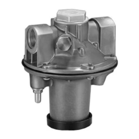
GB-3
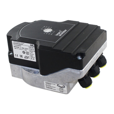
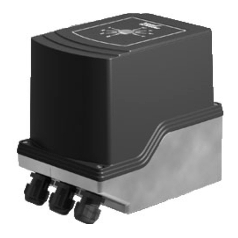
1Solenoid actuator
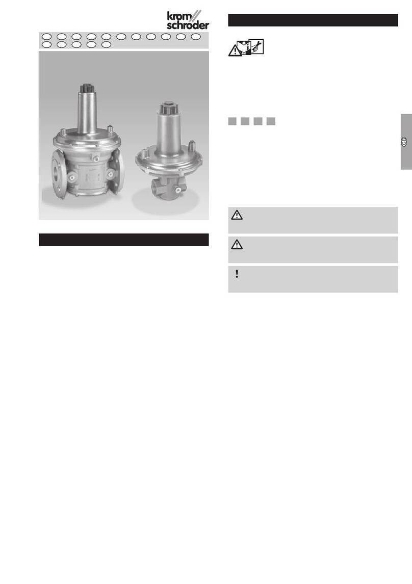
Flow body
3Connection box
4Connection flange
5Closed position indicator CPI
6Connection parts
7Sealing plug
8Regulator
Mains voltage, electrical power consumption, ambi-
ent temperature, enclosure, inlet pressure and instal-
lation position: see type label.
www.kromschroeder.com
Osnabrück, Germany
VAx ...
.XXXX
Installation
CAUTION
Please observe the following to ensure that the unit
is not damaged during installation and operation:
– Dropping the device can cause permanent dam-
age. In this event, replace the entire device and
associated modules before use.
– Important! The gas must be dry in all conditions
and must not contain condensate.
– Sealing material and dirt, e.g. thread cuttings,
must not be allowed to get into the valve hous-
ing. Install a filter upstream of every system.
– Always install an activated carbon filter upstream
of the regulator when air is the medium. Other-
wise, the ageing of elastomer materials will be
accelerated.
– It is not permitted to install gas solenoid
valveVAS downstream of flow rate regula-
torVAH/VRH and upstream of fine-adjusting
valveVMV. The VAS would no longer be able
to perform its function as a second safety valve
if installed in the above-mentioned position.
– Do not store or install the unit in the open air.
– If more than three valVario controls are installed
in line, the controls must be supported.
– Do not clamp the unit in a vice. Only secure the
flange by holding the octagon with a suitable
spanner. Risk of external leakage.
– Devices with POC/CPI VAx..SR/SL: actuator
cannot be rotated.
– In the case of double solenoid valves, the posi-
tion of the connection box can only be changed
by removing the actuator and reinstalling it ro-
tated by 90° or180°.
–
Cleaning work on the solenoid actuator may not be
performed using high pressure and/or chemical clean-
ing agents. This can cause moisture to get into the
solenoid actuator and may lead to a dangerous failure.
– Note the inlet and outlet pressures, see
page16 (Technical data).
▷
When using a non-return gas valveGRS, we
recommend installing the non-return gas valve
upstream of the regulator and downstream of
the gas solenoid valves due to the permanent
pressure loss on theGRS.
▷
When joining two valves, determine the posi-
tion of the connection boxes, push through the
knock-outs in the connection boxes and install a
cable gland set before installation in the pipework.
Order No. for cable gland set:
Size 1: 74921985, size 2: 74921986, size 3:
74921987.
▷
Install the unit in the pipe free of mechanical
stress.
▷
For retrofitting a second gas solenoid valve, use
the double block seal instead of O-rings. The
double block seal is supplied with the seal set.
Order No. for seal set:
Size 1: 74921988, size 2: 74921989, size 3:
74921990.
▷Installation position:
VAD, VAG, VAH: black solenoid actuator in the
vertical upright position or tilted up to the hori-
zontal, not upside down.
VAG/VAH/VRH in the horizontal position with
modulating control: min. inlet pressure pumin. =
80 mbar (32 "WC).
VAV: black solenoid actuator in the vertical posi-
tion, not upside down.
AD, VAG,
AH, VRH
VAV, VAH,
VRH
▷
The housing must not be in contact with masonry.
Minimum clearance 20mm (0.78").
▷
To prevent vibrations, keep the volume between
the regulator and burner small by using short
pipes (≤0.5m, ≤19.7").
▷
The inlet pressurepucan be measured using
pressure test points on the flow body on both
sides.
pu
▷
The outlet pressure p
d
(p
d
and p
d-
) and the air
control pressure psa (psa and psa-) must only
be measured at the designated places on the
regulator using pressure test points.

