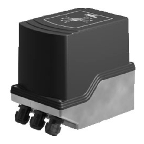
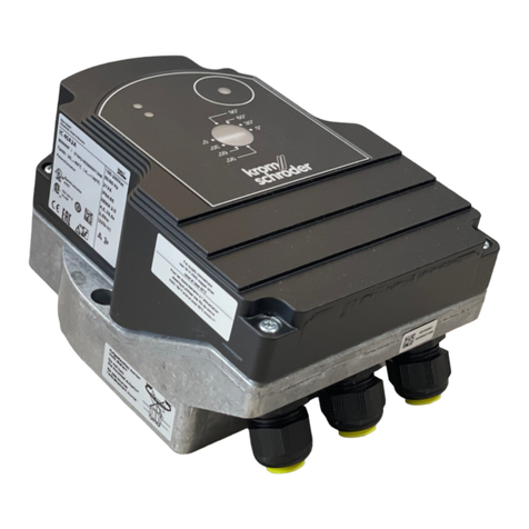
Krom Schroder IC 20 User manual

ADD FURNACE CO.,LTD.
44 ซอยบรมราชชนนี
โทร: 02-888-3472 โทร: ออกแบบ:08-08-170-170 แฟกซ์: 02-888-3258
https://www.add-furnace.com E-mail: sales@add-furnace.com
Actuators IC 20, IC 40
Technical Information ·GB
3Edition 04.14
•IC 20 for applications with continuous or three-point
step control and Automatic/Manual mode-
changeover for easy commissioning, IC 20..E with electronic
positioning function and adjustable behaviour in the event of cable
discontinuity
•IC 40 for complex applications with programmable functions for flexible
adjustment to the process, with statistics and fault history to support
service personnel
•A position indicator that can be read externally
•Spacious connection chamber for ease of installation
•Actuators can be delivered ready installed on butterfly valves BVG, BVGF,
BVA, BVAF, BVH, BVHS or linear flow control VFC

ADD FURNACE CO.,LTD.
44 ซอยบรมราชชนนี
โทร: 02-888-3472 โทร: ออกแบบ:08-08-170-170 แฟกซ์: 02-888-3258
https://www.add-furnace.com E-mail: sales@add-furnace.com
Contents
Actuators IC 20, IC 40 . . . . . . . . . . . . . . . . . . . . . . . . . . . . . . . . . . . . . 1
Contents . . . . . . . . . . . . . . . . . . . . . . . . . . . . . . . . . . . . . . . . . . . . . .. .2
1 Application . . . . . . . . . . . . . . . . . . . . . . . . . . . . . . . . . . . . . . . . . . . .4
1.1 Examples of application. . . . . . . . . . . . . . . . . . . . . . . . . . . . . . . . . . . ..7
1.1.1 IC 20, continuous control. . . . . . . . . . . . . . . . . . . . . . . . . . . . . . . . . .7
1.1.2 IC 20..E, continuous control . . . . . . . . . . . . . . . . . . . . . . . . . . . . . . . 7
1.1.3 IC 20, modulating control with burner control unit BCU 370 . . . .8
1.1.4 IC 40, staged control. . . . . . . . . . . . . . . . . . . . . . . . . . . . . . . . . . . 9
1.1.5 IC 40, staged control with three burner capacity levels. . . . . . . 9
1.1.6 IC 40, continuous control by three-point step signal . . . . . . . . . 10
1.1.7 IC 40, staged control with pre-purge. . . . . . . . . . . . . . . . . . . . . . 11
1.1.8 IC 40, continuous control with defined ignition position. . . . . . 12
1.1.9 IC 40, hot-air compensation. . . . . . . . . . . . . . . . . . . . . . . . . . . . 13
1.1.10 IC 40, staged control with online adjustment of the
burner capacity. . . . . . . . . . . . . . . . . . . . . . . . . . . . . . . . . . . . . . . . 14
2 Certification . . . . . . . . . . . . . . . . . . . . . . . . . . . . . . . . . . . . . .. . . 15
3 IC 20 function . . . . . . . . . . . . . . . . . . . . . . . . . . . . . . . . . . . .. . . . 16
3.1 IC 20..T Connection diagram . . . . . . . . . . . . . . . . . . . . . . . . . . . . . 17
3.2 IC 20..E connection diagram . . . . . . . . . . . . . . . . . . . . . . . . . . . . . 18
3.2.1 Continuous control. . . . . . . . . . . . . . . . . . . . . . . . . . . . . . . . . . . . 18
3.2.2 2-point step control. . . . . . . . . . . . . . . . . . . . . . . . . . . . . . . . . . . . . 18
3.3 IC 20..E Display . . . . . . . . . . . . . . . . . . . . . . . . . . . . . . . . . . . . . . . . . 19
3.3.1 In Manual mode. . . . . . . . . . . . . . . . . . . . . . . . . . . . . . . . . . . . . . . 19
3.3.2 Low-fire/High-fire rate adjustment (in Manual mode
only) . . . . . . . . . . . . . . . . . . . . . . . . . . . . . . . . . . . . . . . . . . . . . . . . . . . . . . 19
3.3.3 Warnings and faults . . . . . . . . . . . . . . . . . . . . . . . . . . . . . .. . . .. . . 19
3.4 IC 20..E DIP switch. . . . . . . . . . . . . . . . . . . . . . . . . . . . . . . . . ... . . ... 20
4 IC 40 function . . . . . . . . . . . . . . . . . . . . . . . . . . . . . . . . . . . . . . . . 21
4.1 Operating modes. . . . . . . . . . . . . . . . . . . . . . . . . . . . . . . . . .. . . . . .22
4.2 Standard and analogue operating modes. . . . . . . . . . .. . . . . . . . 22
4.3 Closed, low-fire rate, intermediate and open position . . . . . . .. 22
4.4 Running times. . . . . . . . . . . . . . . . . . . . . . . . . . . . . . . . . . . . . . . . . . . 23
4.5 Standard operating modes 1 –12. . . . . . . . . . . . . . . . . . . . . . . .. . 24
4.5.1 2-point operation. . . . . . . . . . . . . . . . . . . . . . . . . . . . . . . . . . . . .... 24
4.5.2 2-point operation with flame proving period . . . . . . . . . . . . . ..... 25
4.5.3 2-step operation with one or two digital inputs . . . . . . . . . .
...
. 26
4.5.4 2-step operation with two digital inputs . . . . . . . . . . . . . . . . . . . . 28
4.5.5 3-point step operation. . . . . . . . . . . . . . . . . . . . . . . . . . . . . . . . . . 29
4.5.6 3-step operation with one or two digital inputs . . . . . . . . . . . . . . 30
4.5.7 2-point operation with switchover of the adjustment
angle for the “open” position. . . . . . . . . . . . . . . . . . . . . . . . . . . . . . . . . 32
4.5.8 2-point operation with input-dependent adjustment
angle for the “open” position. . . . . . . . . . . . . . . . . . . . . . . . . . . . . . . . . . . 34
4.5.9 2-point operation with switchover of the running times. . . . . . . . . .35
4.5.10 3-point step operation with running time fractions. . . . . . . . . . . . 36
4.5.11 3-step operation with two digital inputs . . . . . . . . . . . . . . . . . . . . . 38
4.5.12 3-point step operation with low position . . . . . . . . . . . . . . . . . . . . .39
4.6 Analogue operating modes 21 –27. . . . . . . . . . . . . . . . . . . . . . . . . . .40
4.6.1 2-point operation . . . . . . . . . . . . . . . . . . . . . . . . . . . . . . . . . . . . . . . . .40
4.6.2 2-point operation with switchover of the adjustment
angle for the “open” position. . . . . . . . . . . . . . . . . . . . . . . . . . . . . . . . . . .42
4.6.3 2-point operation with input-dependent adjustment
angle for the “open” position. . . . . . . . . . . . . . . . . . . . . . . . . . . . . . . . . . . 44
4.6.4 2-point operation with switchover of the running times. . . . . . . . . .45
4.6.5 2-point operation with characteristic curve switchover I . . . . . . . .47
4.6.6 2-point operation with characteristic curve switchover II . . . . . . . 49
4.6.7 2-step operation with two digital inputs and variable
adjustment angl . . . . . . . . . . . . . . . . . . . . . . . . . . . . . . . . . . . . . . . . . . . . . .51
4.6.8 Safety closing function. . . . . . . . . . . . . . . . . . . . . . . . . . . . . . . . . . . . .52
4.7 Parameters . . . . . . . . . . . . . . . . . . . . . . . . . . . . . . . . . . . . . . . . . . . . . . . 53
4.7.1 Parameter sets . . . . . . . . . . . . . . . . . . . . . . . . . . . . . . . . . . . . . . . . . . .54
4.7.2 Factory default parameters. . . . . . . . . . . . . . . . . . . . . . . . . . . . . . . . 56
4.8 Inputs. . . . . . . . . . . . . . . . . . . . . . . . . . . . . . . . . . . . . . . . . . . . . . . . . . . . .57
4.8.1 Digital . . . . . . . . . . . . . . . . . . . . . . . . . . . . . . . . . . . . . . . . . . . . . . . . . . 57
4.8.2 Analogue . . . . . . . . . . . . . . . . . . . . . . . . . . . . . . . . . . . . . . . . . . . . . . . 57
4.9 Outputs . . . . . . . . . . . . . . . . . . . . . . . . . . . . . . . . . . . . . . . . . . . . . . . . . . 59
4.10 Manual mode . . . . . . . . . . . . . . . . . . . . . . . . . . . . . . . . . . . . . . . . . . . .60
4.10.1 Direct position preset . . . . . . . . . . . . . . . . . . . . . . . . . . . . . . . . . . . . 60
4.10.2 Simulate inputs. . . . . . . . . . . . . . . . . . . . . . . . . . . . . . . . . . . . . . . . . . 60
4.11 Statistics. . . . . . . . . . . . . . . . . . . . . . . . . . . . . . . . . . . . . . . . . . . . . . . . . .61
4.11.1 Counters. . . . . . . . . . . . . . . . . . . . . . . . . . . . . . . . . . . . . . . . . . . . . . . 61
4.11.2 Measured values . . . . . . . . . . . . . . . . . . . . . . . . . . . . . . . . . . . . . . . .61
4.11.3 Resetting statistics. . . . . . . . . . . . . . . . . . . . . . . . . . . . . . . . . . . . . . . 61
4.11.4 Resetting a signal . . . . . . . . . . . . . . . . . . . . . . . . . . . . . . . . . . . . . . . 61
4.12 IC 40 connection diagram . . . . . . . . . . . . . . . . . . . . . . . . . . . . . . . . . 62
4.13 Display . . . . . . . . . . . . . . . . . . . . . . . . . . . . . . . . . . . . . . . . . . . . . . . . . . 63
4.13.1 During operation. . . . . . . . . . . . . . . . . . . . . . . . . . . . . . . . . . . . . . . . 63
4.13.2 Warnings and faults. . . . . . . . . . . . . . . . . . . . . . . . . . . . . . . . . . . . . . 63
4.14 Relay outputs RO 1 and RO 2 function .. . . . . . . . . . . . . . . . . . . . . . .65
5 Replacement possibilities for actuators . . . . . . . . . . . . . . . . . . . . . . . . .66
ADD FURNACE CO.,LTD.
44 ซอยบรมราชชนนี
โทร: 02-888-3472 โทร: ออกแบบ:08-08-170-170 แฟกซ์: 02-888-3258
https://www.add-furnace.com E-mail: sales@add-furnace.com
5.1 GT 31 is to be replaced with IC 20 . . . . . . . . . . . . . . . . . . . . . . . . . 66
5.2 GT 31 is to be replaced with IC 40 . . . . . . . . . . . . . . . . . . . . . . . . . 67
5.3 M5/M6 is to be replaced with IC 40 . . . . . . . . . . . . . . . . . . . . . . .. 68
6 Selection . . . . . . . . . . . . . . . . . . . . . . . . . . . . . . . .. . . . . . . . . . . . . 69
6.1 IC 20, IC 40. . . . . . . . . . . . . . . . . . . . . . . . . . . . . . . . . . . . . . . . . . . . . .69
6.1.1 Type code . . . . . . . . . . . . . . . . . . . . . . . . . . . . . . . . . . . . . . . . . . . . 69
7 Project planning information . . . . . . . . . . . . . . . . . . . . . . . . . . . . 70
7.1 Electrical connection. . . . . . . . . . . . . . . . . . . . . . . . . . . . . . . . . . . . .70
7.1.1 Cable selection . . . . . . . . . . . . . . . . . . . . . . . . . . . . . . . . . . . . . . . 70
7.1.2 IC 20. . . . . . . . . . . . . . . . . . . . . . . . . . . . . . . . . . . . . . . . . . . . . . . . . 70
7.1.3 IC 20.E. . . . . . . . . . . . . . . . . . . . . . . . . . . . . . . . . . . . . . . . . . . . . . . . 70
7.1.4 IC 40 . . . . . . . . . . . . . . . . . . . . . . . . . . . . . . . . . . . . . . . . . . . . . . . . . 70
7.2 Feedback potentiometer. . . . . . . . . . . . . . . . . . . . . . . . . . . . . . . . . 72
7.3 Installation . . . . . . . . . . . . . . . . . . . . . . . . . . . . . . . . . . . . . . . . . . . . . .73
7.4 IC 40 commissioning. . . . . . . . . . . . . . . . . . . . . . . . . . . . . . . . . . . . . .73
8 Accessories . . . . . . . . . . . . . . . . . . . . . . . . . . . . . . . . . . . . . . . . . . 74
8.1 IC 20, IC 40 Heat deflectors . . . . . . . . . . . . . . . . . . . . . . . . . . . . . . . 74
8.2 Adapter set for mounting an actuator IC 20, IC 40
onto a butterfly valve DKL, DKG . . . . . . . . . . . . . . . . . . . . . . . . . . . . . . 74
8.3 IC 20, IC 40 “single application” attachment set. . . . . . . . . . . . . .74
8.4 IC 20 potentiometer installation set. . . . . . . . . . . . . . . . . . . . . . . . .75
8.5 BCSoft® . . . . . . . . . . . . . . . . . . . . . . . . . . . . . . . . . . . . . . . . . . . . . . ...75
8.5.1 Opto-adapter PCO 200 . . . . . . . . . . . . . . . . . . . . . . . . . . . . . . . . .75
8.5.2 Bluetooth adapter PCO 300 . . . . . . . . . . . . . . . . . . . . . . . . . . . . . 75
9 Technical data . . . . . . . . . . . . . . . . . . . . . . . . . . . . . . . . . . . . . . . .76
9.1 IC 20, IC 20.E. . . . . . . . . . . . . . . . . . . . . . . . . . . . . . . . . . . . . . . . . . . . 76
9.1.1 IC 20. . . . . . . . . . . . . . . . . . . . . . . . . . . . . . . . . . . . . . . . . . . . . . . . . 76
9.1.2 IC 20.E. . . . . . . . . . . . . . . . . . . . . . . . . . . . . . . . . . . . . . . . . . . . . . . . 76
9.2 IC 40. . . . . . . . . . . . . . . . . . . . . . . . . . . . . . . . . . . . . . . . . . . . . . . . . . . 77
9.3 Running times and torques . . . . . . . . . . . . . . . . . . . . . . . . . . . . . . . .78
9.4 Dimensions of IBG/IBA (BVG/BVA + IC 20/IC 40. . . . . . . . . . . . . . . 79
9.4.1 With full bore = nominal diameter . . . . . . . . . . . . . . . . . . . . . . . . 79
9.4.2 With 1 × reduced bore. . . . . . . . . . . . . . . . . . . . . . . . . . . . . . . . . . 79
9.4.3 With 2 × reduced bore . . . . . . . . . . . . . . . . . . . . . . . . . . . . . . . . . .79
9.5 Dimensions of IBGF/IBAF (BVGF/BVAF + IC 20/IC 40) . . . . . . . . . . 80
9.5.1 With full bore = nominal diameter . . . . . . . . . . . . . . . . . . . . . . . . 80
9.5.2 With 1 × reduced bore. . . . . . . . . . . . . . . . . . . . . . . . . . . . . . . . . . 80
9.5.3 With 2 × reduced bore . . . . . . . . . . . . . . . . . . . . . . . . . . . . . . . . . .80
9.6 Dimensions of IBH/IBHS (BVH/BVHS + IC 20/IC 40) . . . . . . . . . . . . . 81
9.7 Dimensions IFC, IFC.T (VFC + IC 20/IC 40) . . . . . . . . . . . . . . . . . . . 82
10 Maintenance cycles . . . . . . . . . . . . . . . . . . . . . . . . . . . . . . . . . .83
11 Glossary . . . . . . . . . . . . . . . . . . . . . . . . . . . . . . . . . . . . . . . . . . . . 84
11.1 Start fuel flow rate. . . . . . . . . . . . . . . . . . . . . . . . . . . . . . . . . . . . . . 84
11.2 Positions . . . . . . . . . . . . . . . . . . . . . . . . . . . . . . . . . . . . .84
11.3 Adjustment angle for the “open” position. . . . . . . . .84
12 Legend . . . . . . . . . . . . . . . . . . . . . . . . . . . . . . . . . . . . 85
Feedback . . . . . . . . . . . . . . . . . . . . . . . . . . . . . . . . . . . . 86
Contact . . . . . . . . . . . . . . . . . . . . . . . . . . . . . . . . . . . . . . .86
Contents

ADD FURNACE CO.,LTD.
44 ซอยบรมราชชนนี
โทร: 02-888-3472 โทร: ออกแบบ:08-08-170-170 แฟกซ์: 02-888-3258
https://www.add-furnace.com E-mail: sales@add-furnace.com
1 Application
The actuators IC 20 and IC 40 are designed for all
applications that require precise, controlled rotary
movement between 0° and 90°. They can be mounted
directly onto the butterfly valves BVG, BVGF, BVA, BVAF,
BVH, BVHS or linear flow control VFC in order to control the
gas and air flow rates on gas burners.
Actuators and butterfly valves BVG, BVGF, BVA, BVAF, BVH,
BVHS or linear flow control VFC can also be delivered ready
assembled as butterfly valves with actuator IBG, IBGF, IBA,
IBAF, IBH, IBHS or linear flow control IFC.
IBG 80 (IC 20 + BVG 80) IFC (IC 20 + VFC)
An optional integrated feedback potentiometer offers the
op-tion of monitoring the current position of the actuator.
This checking function can be used in automation
processes.
IC 20
IC 20 is ontrolled by a continuous signal or three-point step
signal. The Automatic/Manual mode changeover and the
posi-tion indicator that can be read externally assist in the
setting of the infinitely adjustable switching cams upon
commissioning. This enables precise settings even in the low-
fire rate range.
4

ADD FURNACE CO.,LTD.
44 ซอยบรมราชชนนี
โทร: 02-888-3472 โทร: ออกแบบ:08-08-170-170 แฟกซ์: 02-888-3258
https://www.add-furnace.com E-mail: sales@add-furnace.com
Application
IC 40
The IC 40 offers additional functions. It can be used in con-
tinuously-controlled burners and in stage-controlled burners.
Settings on the actuator IC 40 can be made using a PC with the
parameterization software BCSoft®. All the relevant settings for the
process are made using the software via an optical interface.
Various operating modes, which may be modified, are stored in
the unit. In addition, the control type (two-point signal, three-
point step signal or continuous control), running times, adjustment
angles and intermediate positions can be programmed.
The actuator can also be controlled “by hand” using the soft-
ware.
Once set, all the parameters can be saved on the PC and
copied from there into other actuators, thus saving time dur-ing
the commissioning process.
Service technicians can call up statistical data using
BCSoft®, such as hours of operation, actuating cycles and
a faul history. Some values can also be set to zero, for
example to record data over a specific period of time.

ADD FURNACE CO.,LTD.
44 ซอยบรมราชชนนี
โทร: 02-888-3472 โทร: ออกแบบ:08-08-170-170 แฟกซ์: 02-888-3258
https://www.add-furnace.com E-mail: sales@add-furnace.com
Application
IC 20 with BVG 80
Roller hearth kiln in the ceramics industry Forging furnace

ADD FURNACE CO.,LTD.
44 ซอยบรมราชชนนี
โทร: 02-888-3472 โทร: ออกแบบ:08-08-170-170 แฟกซ์: 02-888-3258
https://www.add-furnace.com E-mail: sales@add-furnace.com
Application
1.1 Examples of application
1.1.1 IC 20, continuous control
For processes that require high
temperature accuracy and low
circulation in the furnace.
The actuator IC 20 is controlled
by a three-point step controller.
1.1.2 IC 20.E, continuous control
For processes that require high
temperature accuracy and low
circulation in the furnace. The
actuator IC 20..E is controlled by a
4 – 20 mA, 0 – 20 mA or
0 – 10 V signal.

ADD FURNACE CO.,LTD.
44 ซอยบรมราชชนนี
โทร: 02-888-3472 โทร: ออกแบบ:08-08-170-170 แฟกซ์: 02-888-3258
https://www.add-furnace.com E-mail: sales@add-furnace.com
Application > Examples of application
1.1.3 IC 20, modulating control with
burner control unit BCU 370
This connection option can be used
on modulating forced draught
burners. The BCU 370 controls the fan
and moves the butterfly valve to pre-
purge and ignition position. After pre-
purge and burner start, the controller
enable signal is is-sued to an external
three- point step controller which
positions the butterfly valve in
accordance with the capacity
demand.
The “Close contact” (90° 0°) of the
external three -point step controller
(3PS) can be connected to terminal
26 or 27 of the BCU 370.
Terminal 26: the controller operates
be-tween the open and ignition
positions.
Terminal 27: the controller operates
be-tween the open and closed
positions.

ADD FURNACE CO.,LTD.
44 ซอยบรมราชชนนี
โทร: 02-888-3472 โทร: ออกแบบ:08-08-170-170 แฟกซ์: 02-888-3258
https://www.add-furnace.com E-mail: sales@add-furnace.com
Application > Examples of application
1.1.4 IC 40, staged control
For processes that require a
homogeneous temperature
distribution in the
furnace. The actuator IC 40 is
controlled by a two-point controller
and operates in On/Off or High/Low
intermittent mode.
The actuator closes when the voltage
supply is interrupted. The running time
can be adjusted between 5 and 25
seconds.
1.1.5
IC40,stagedcontrolwiththreeburner
capacity levels
For processes that require a
homogeneous temperature
distribution in the furnace and three
burner capacity levels. The actuator
IC 40 is controlled by a
programmable controller and works
in High/Medium/Low or High/Medium/
Low/Off intermittent mode. This allows
the ignition stage to be started. The
optional pressure switch provides fail-
safe monitoring of the maximum pilot
air volume. The actuator running time
can be adjusted between 5 and 50
(75) seconds.

ADD FURNACE CO.,LTD.
44 ซอยบรมราชชนนี
โทร: 02-888-3472 โทร: ออกแบบ:08-08-170-170 แฟกซ์: 02-888-3258
https://www.add-furnace.com E-mail: sales@add-furnace.com
Application > Examples of application
1.1.6 IC 40, continuous control by three-point step signal
The actuator IC 40 is controlled by the three -point step
controller 3PS and moves the butterfly valve BVA to the
ignition position. The burner starts.
Once the burner is operating, the operation signalling
contact of the burner control unit BCU 460 closes. The BCU
issues the controller enable signal to the temperature
controller. The butterfly valve opens or closes between the
low-fire and high-fire rate positions depending on the
capacity demand of the burner. When the three -point
step signal is disconnected, the butterfly valve stops at its
current position.
If both inputs on the IC 40 (DI 1 and DI 2) are actuated
after the burner has been shut down, the butterfly valve
closes further than the low-fire rate position (see
Operating mode 12, 3-point step operation with low
position)
DI 1
DI 2
IC 40 position
Valve position
Off
Off
Idle/Stop
Idle
On
Off
Open to high position
Open to high-fire rate
Off
On
Close to middle position
Close to low-fire rate
On
On
low
Valve closes further

ADD FURNACE CO.,LTD.
44 ซอยบรมราชชนนี
โทร: 02-888-3472 โทร: ออกแบบ:08-08-170-170 แฟกซ์: 02-888-3258
https://www.add-furnace.com E-mail: sales@add-furnace.com
Application > Examples of application
1.1.7 IC 40, staged control with pre-purge
The central control system starts the pre-purge. Input DI 2
is actuated via the air valve output of the BCU and
moves the butterfly valve BVA to the pre-purge position.
In the event of a temperature demand, the burner control
unit BCU actuates input DI 1 via the valve output V1 and
moves the butterfly valve to the ignition position.
(Precondition: the IC 40 must have reached the ignition
position on the instant of ignition.) The burner starts.
To activate the high -fire rate, DI 2 is actuated via the air
valve output on terminal 26 of the BCU.
The butterfly valve moves cyclically between the high-fire
rate position and the low-fire rate position (see Operating
mode 11, 2-step operation with two digital inputs).
DI 1/
DI 2/
IC 40
Valve position
V1
air Valve
position
Off
Off
closed
Closed
On
Off
low
Ignition position/low-fire rate
On
On
middle
High-fire rate
Off
On
high
Pre-purge

ADD FURNACE CO.,LTD.
44 ซอยบรมราชชนนี
โทร: 02-888-3472 โทร: ออกแบบ:08-08-170-170 แฟกซ์: 02-888-3258
https://www.add-furnace.com E-mail: sales@add-furnace.com
Application > Examples of application
1.1.8 IC 40, continuous control with defined ignition
position
The central control system starts the pre-purge. Input DI 2
is actuated via the air valve output of the BCU and moves
the butterfly valve BVA to the pre-purge position.
In the event of a temperature demand, the burner control
unit BCU actuates input DI 1 via the valve output V1 and
moves the butterfly valve to the ignition position.
(Precondition: the IC 40 must have reached the ignition
position on the instant of ignition.) The burner starts.
The BCU actuates DI 2 via the air valve output. This enables
the analogue input AI on the actuator IC 40. Depending
on the capacity demand of the temperature controller,
the butterfly valve BVA moves steplessly to the position
between the low-fire rate and the high-fire rate as
specified by the analogue input AI (see Operating mode
27, 2-step operation with two digital inputs and variable
adjustment angle).
DI 1/
DI 2/
IC 40
Valve position
V1
air valve
position
Off
Off
closed
Closed
On
Off
low
Ignition position/low-fire rate
On
On
AI
Any position between ignition
position and pre-purge
Off
On
high
Pre-purge/high-fire rate

ADD FURNACE CO.,LTD.
44 ซอยบรมราชชนนี
โทร: 02-888-3472 โทร: ออกแบบ:08-08-170-170 แฟกซ์: 02-888-3258
https://www.add-furnace.com E-mail: sales@add-furnace.com
Application > Examples of application
1.1.9 IC 40, hot-air compensation
For processes in which preheated
combustion air at a temperature of
up to 450°C must be controlled. In this
example, the actuator IC 40 is
regulated by a two-point controller to
adjust the burner capacity. It runs in
High/Low intermittent mode. The
running time can be adjusted
between 5 and 25 seconds.

ADD FURNACE CO.,LTD.
44 ซอยบรมราชชนนี
โทร: 02-888-3472 โทร: ออกแบบ:08-08-170-170 แฟกซ์: 02-888-3258
https://www.add-furnace.com E-mail: sales@add-furnace.com
Application > Examples of application
1.1.10 IC 40, staged control with
online adjustment of the burner
capacity
For processes that require a
homogeneous temperature distribution
and high temperature accuracy in
the furnace.
If only a low heat output is required,
for example to maintain the
temperature in the furnace, the
burner can continue to run in
intermittent mode. The adjustment
angle of the valve is reduced by the
analogue input (4 – 20 mA) of the
actuator and the burner capacity is
therefore lowered. This ensures
uniform temperature distribution even
with a low burner capacity.
This function of the actuator IC 40 can
also be used in the ceramics industry
to correct the lambda value or for
temperature compensation purposes
in hot-air applications.

ADD FURNACE CO.,LTD.
44 ซอยบรมราชชนนี
โทร: 02-888-3472 โทร: ออกแบบ:08-08-170-170 แฟกซ์: 02-888-3258
https://www.add-furnace.com E-mail: sales@add-furnace.com
2 Certification
EC type-tested and certified
Meets the requirements of the
–Low Voltage Directive (2006/95/EC) on the
basis of EN 60730-1,
–Electromagnetic Compatibility Directive (2004/108/EC).
Approval for Russia
Certified by Gosstandart pursuant to GOST R.
Approved by Rostekhnadzor (RTN).
Scan of the approval for Russia (RUS), see www.docuthek.com
→Elster Kromschröder→Kromschröder,
LBE→Products→03 Valves and butterfly
valves→Actuators IC 20, IC 40→Type of document:
Certificate→IC B00069 (nationales Zertifikat
Russland) (RUS)

ADD FURNACE CO.,LTD.
44 ซอยบรมราชชนนี
โทร: 02-888-3472 โทร: ออกแบบ:08-08-170-170 แฟกซ์: 02-888-3258
https://www.add-furnace.com E-mail: sales@add-furnace.com
3 IC 20 function
The actuator IC 20 moves towards 0°or 90°if it is energized
electrically at the related terminal. If the voltage is
disconnected, the actuator stops at the current position. A
high holding torque when de-energized renders additional
braking elements su-perfluous. The low-fire and high-fire
rates are adjusted using two infinitely adjustable switching
cams (S3, S4). An optional integrated feedback
potentiometer offers the option of moni-toring the current
position of the actuator.
The actuator IC 20 is optimally tailored to the
Kromschröder butterfly valves BVG, BVGF, BVA, BVAF,
BVH, BVHS or linear flow control VFC.
IC 20.E
In normal operation, input “OK” is supplied with voltage.
The setpoint device issues an actuating signal (0 (4) – 20
mA, 0 – 10 V). The current signal corresponds to the
adjustment angle to be approached (e.g. with a 0 – 20
mA signal, 10 mA correspond to a valve angle of 45°). The
minimum and maxi-mum adjustment angles can be set
manually using the keys. The hysteresis can be adjusted on
a potentiometer to suppress interference in the input
signal.
The IC 20..E offers the option of monitoring the current
position of the actuator via the continuous 4 – 20 mA
output signal.
Automatic/Manual mode
Switchover between Automatic and Manual mode
facilitates setting of the infinitely adjustable switching
cams during com-missioning. This enables precise settings
even in the low-fire rate range.
The switching point is set directly on the cams with a
screw-driver.
External devices can be activated or intermediate
positions can be checked via two additional, floating,
infinitely adjust-able switches.

ADD FURNACE CO.,LTD.
44 ซอยบรมราชชนนี
โทร: 02-888-3472 โทร: ออกแบบ:08-08-170-170 แฟกซ์: 02-888-3258
https://www.add-furnace.com E-mail: sales@add-furnace.com
IC 20 function
3.1 IC 20..T Connection diagram
See page 70 (Project planning infor-
mation).
See page 76 (Technical data).

ADD FURNACE CO.,LTD.
44 ซอยบรมราชชนนี
โทร: 02-888-3472 โทร: ออกแบบ:08-08-170-170 แฟกซ์: 02-888-3258
https://www.add-furnace.com E-mail: sales@add-furnace.com
IC 20 function
3.2 IC 20..E connection diagram
See page 70 (Project planning infor-
mation).
See page 76 (Technical data).
3 .2 .1 Continuous control
Following successful modulation
enable via terminal 5(OK), the
actuator reacts to the setpoint
specification (0 (4) –20 mA,
0 –10 V) via terminals 17 and 18.
The pre-purge and ignition positions
are controlled via terminals 1 and 2.
3.2.2 2-point step control
Connect voltage to terminals 1 and 3.
Set the DIP switch to 2-point step
control, see page 20 (IC 20..E DIP
switch).
If an input signal is applied to terminal
5(OK), the actuator opens. If no input
signal is applied to terminal 5, the ac-
tuator closes.
Terminals 17 and 18 for continuous
control are not required in the case of
2-point control

ADD FURNACE CO.,LTD.
44 ซอยบรมราชชนนี
โทร: 02-888-3472 โทร: ออกแบบ:08-08-170-170 แฟกซ์: 02-888-3258
https://www.add-furnace.com E-mail: sales@add-furnace.com
IC 20 function
3 .3 IC 20..E Display
3.3.1 In Manual mode
Blue LED Red LED Operating state
On Off Manual mode
Flashing Flashing Calibration (in Manual mode only)
3 .3 .2 Low-fire/High-fire rate adjustment (in Manual mode only)
Blue LED Red LED Operating state
On On for 0.5 s Min. value ≥ max. value*
Off for ≤ 0.5 s Off Min. or max. setting accepted
* Value will only be accepted, if the Min. or Max. button is pressed for another three seconds
3 .3 .3 Warnings and faults
Blue LED Red LED Warning/fault Description Cause
Off Flashing light (1×) Warning The device is in 4 –20 mA mode, - Cable discontinuity on the
the input signal is < 3 mA 4 –20 mA set point input
Off Flashing light (2×) Warning Many changes of direction, input - Hysteresis set too small
signal oscillates
Off Flashing light (3×) Warning Control range < 1° - Device programming error
(min. and max. setting)
- Control range < 1°(cams
Flashing light (1×) Permanent light Fault Calibration not successful overlapping), motor
defective, gear defective,
potenti-ometer defective
Flashing light (2×) Permanent light Fault Internal fault - Unit defective

ADD FURNACE CO.,LTD.
44 ซอยบรมราชชนนี
โทร: 02-888-3472 โทร: ออกแบบ:08-08-170-170 แฟกซ์: 02-888-3258
https://www.add-furnace.com E-mail: sales@add-furnace.com
IC 20 function
3 .4 IC 20..E DIP switch
The setpoint device input, the load
impedance of the current input,
the behaviour in the event of
cable discontinuity
(4 –20 mA) or 2-point step
control are set by means of a DIP
switch on the actuator.
Other manuals for IC 20
1
This manual suits for next models
1
Table of contents
Other Krom Schroder Controllers manuals

Krom Schroder
Krom Schroder IC 20 User manual

Krom Schroder
Krom Schroder GDJ 15 User manual

Krom Schroder
Krom Schroder TC 410 User manual

Krom Schroder
Krom Schroder IC 50 Series User manual

Krom Schroder
Krom Schroder Lago Basic 0201 R V1 User manual

Krom Schroder
Krom Schroder VGBF 15R User manual

Krom Schroder
Krom Schroder IC 20 User manual

Krom Schroder
Krom Schroder IC 40 User manual

Krom Schroder
Krom Schroder VGBF Series User manual

Krom Schroder
Krom Schroder IC 50 User manual