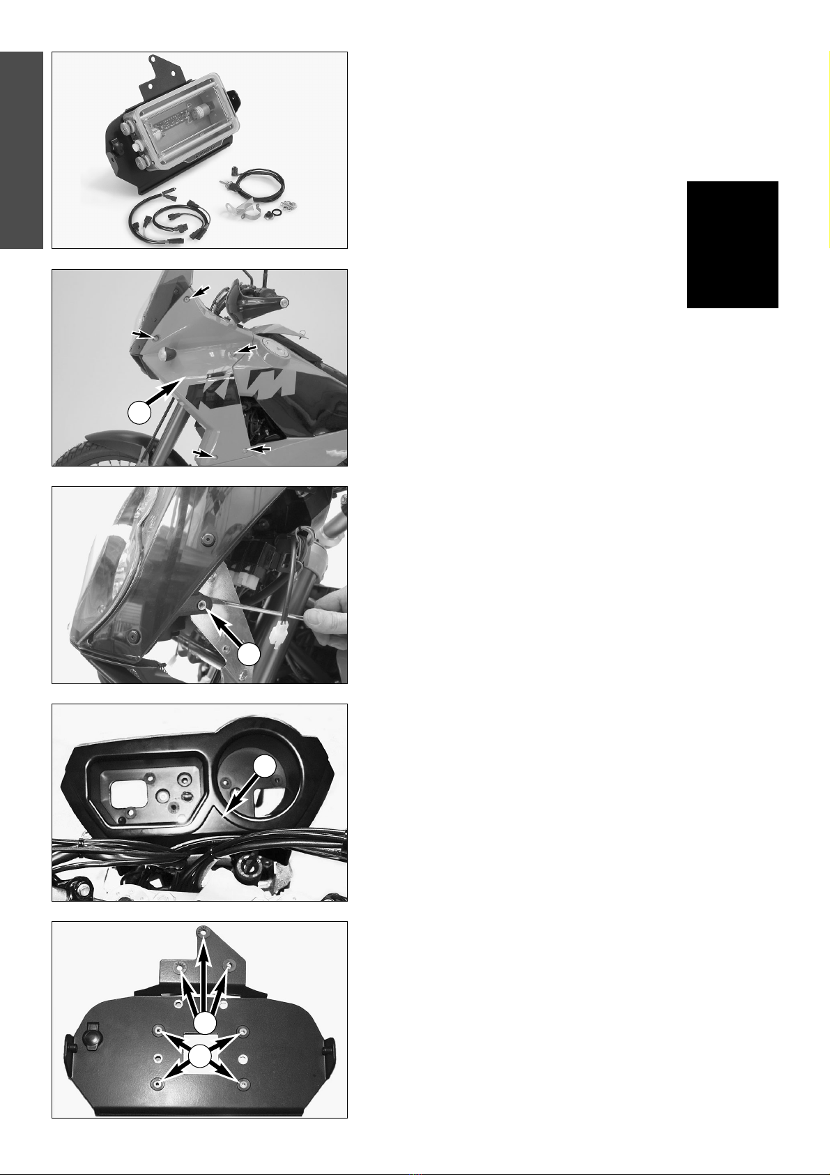
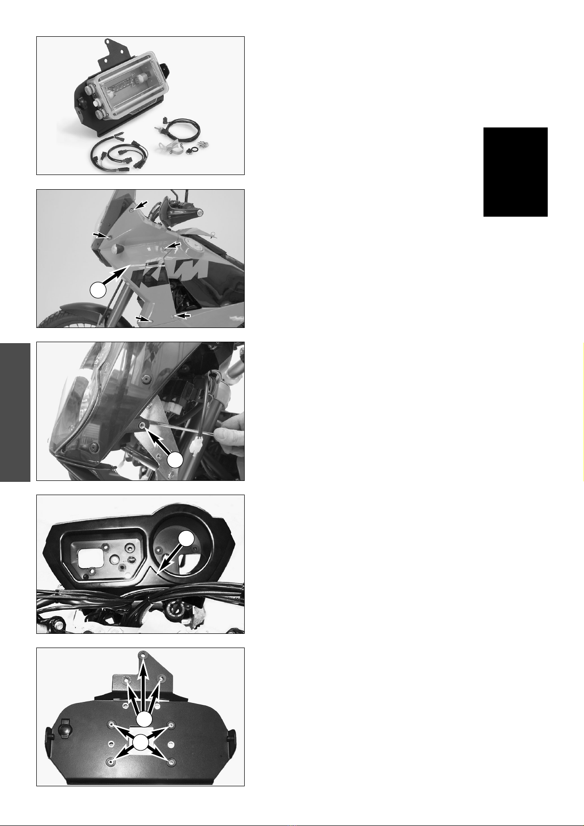
KTM 600.12.073.044 User manual

Information
Hard Equipment
Einbauanleitung Roadbookhalter
Modelle 950 Adventure, 950 Adventure S
Mounting Instructions for the Road Book Holder
950 Adventure, 950 Adventure S models
Istruzioni di Montaggio Porta Road Book
Modelli 950 Adventure, 950 Adventure S
Notice de montage dévideur de roadbook
Modèles 950 Adventure, 950 Adventure S
KTM Teilenummer / KTM Partnumber
600.12.073.044
Art.Nr. 3.210.97
2. 2003

Lieferumfang
1 x Roadbookhalter RB-TT 600.12.073.000
1 x Montageplatte 600.12.073.050
1 x Lenkerfernbedienung mit Kabelsatz und
Montagematerial 600.12.073.080
1 x DIN- Bordnetzsteckdose 12V abgedeckt 600.11.042.000
1 x Kabelsatz für Anschluss von Steckdose 600.11.042.050
1 x Kabelsatz für Anschluss von Roadbookhalter RB-TT 600.12.073.060
4 x Linsenkopfschraube M5 600.12.073.070
2 x Senkkopfschraube M6x25
2 x Senkkopfschraube M6x30
4 x Kunststoffdistanzen
4 x Gummielemente
4 x Kunststoffhülsen
1 x Mutternplatte 4xM5
2 x Mutter M6
2 x Beilagscheibe M6
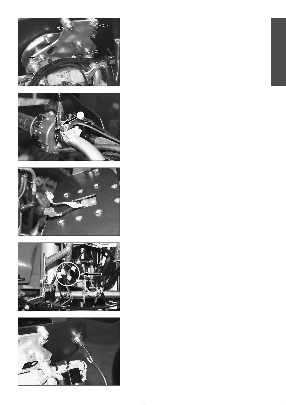
Montage
Lösen Sie zunächst links und rechts die 5 Befestigungsschrauben und entfer-
nen Sie beide Seitenverkleidungen 1.
DEUTSCH
2
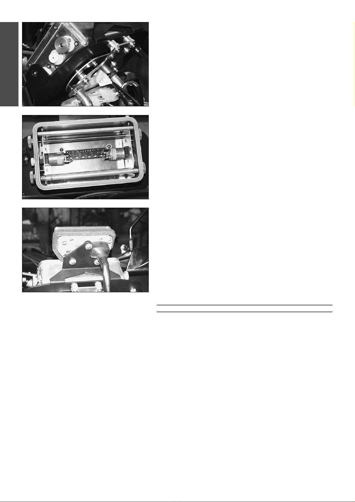
Hängen Sie nun mit einen Schraubenzieher die Haltelasche 2aus, schwen-
ken Sie dann Windschild samt Scheinwerfer nach vorne und ziehen Sie den
Stecker vom Steckerboard ab.
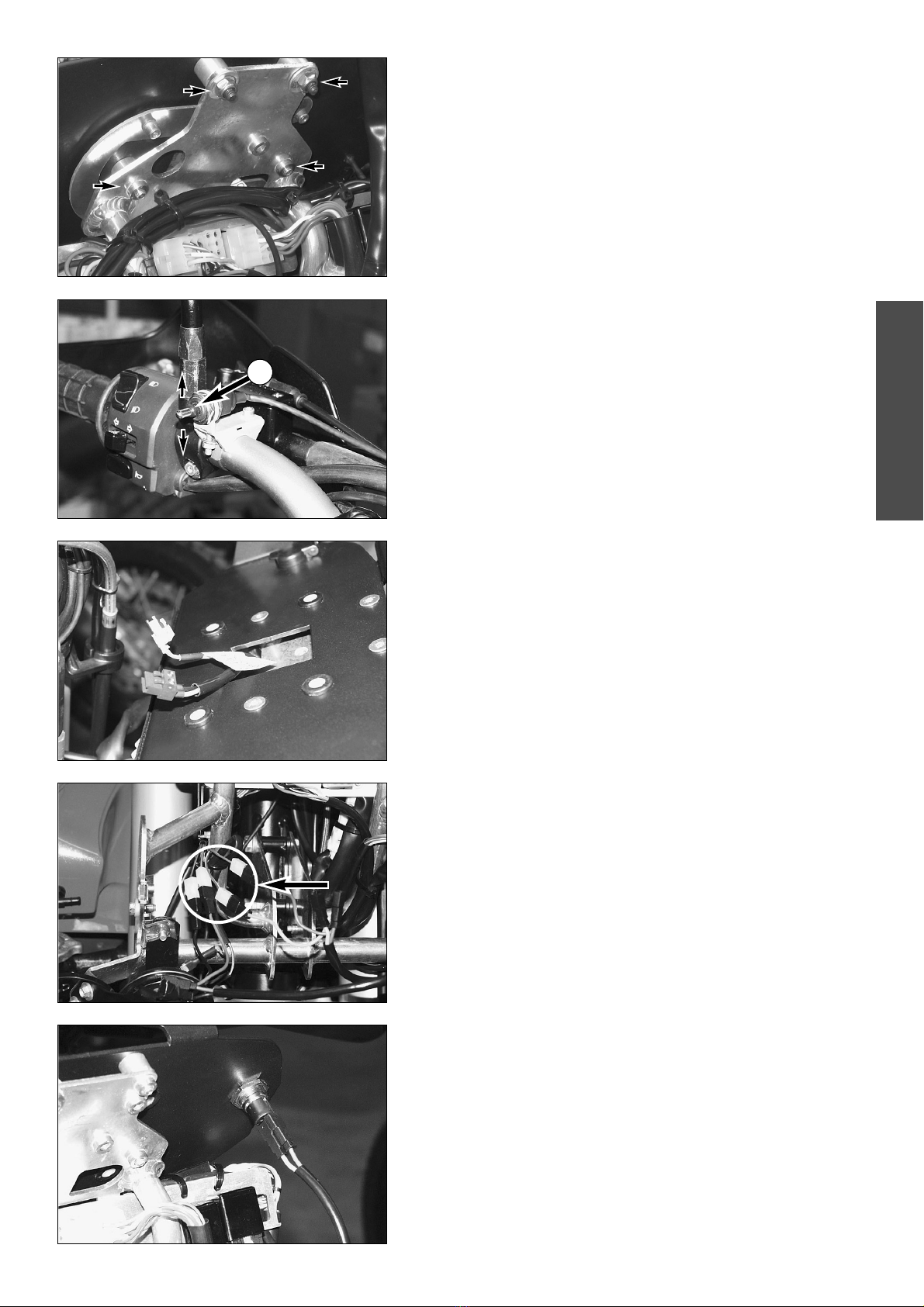
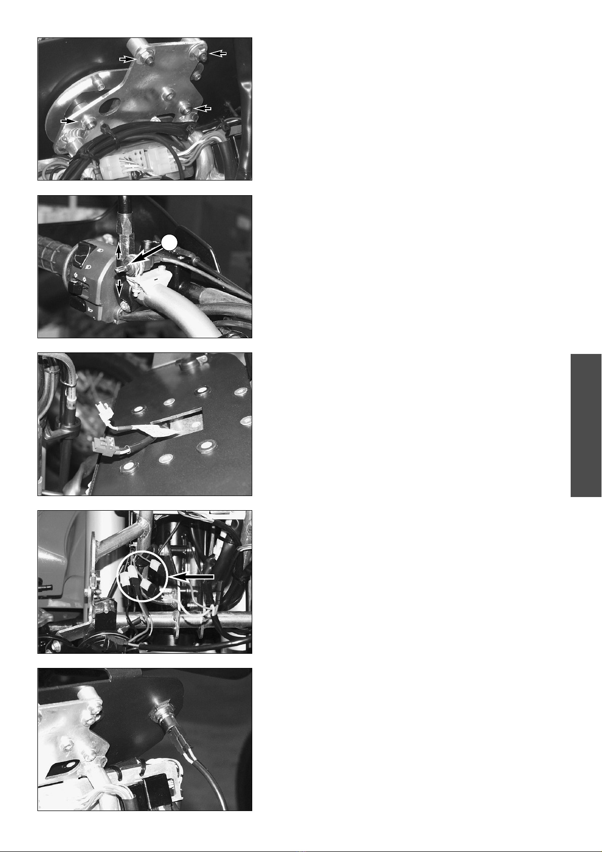
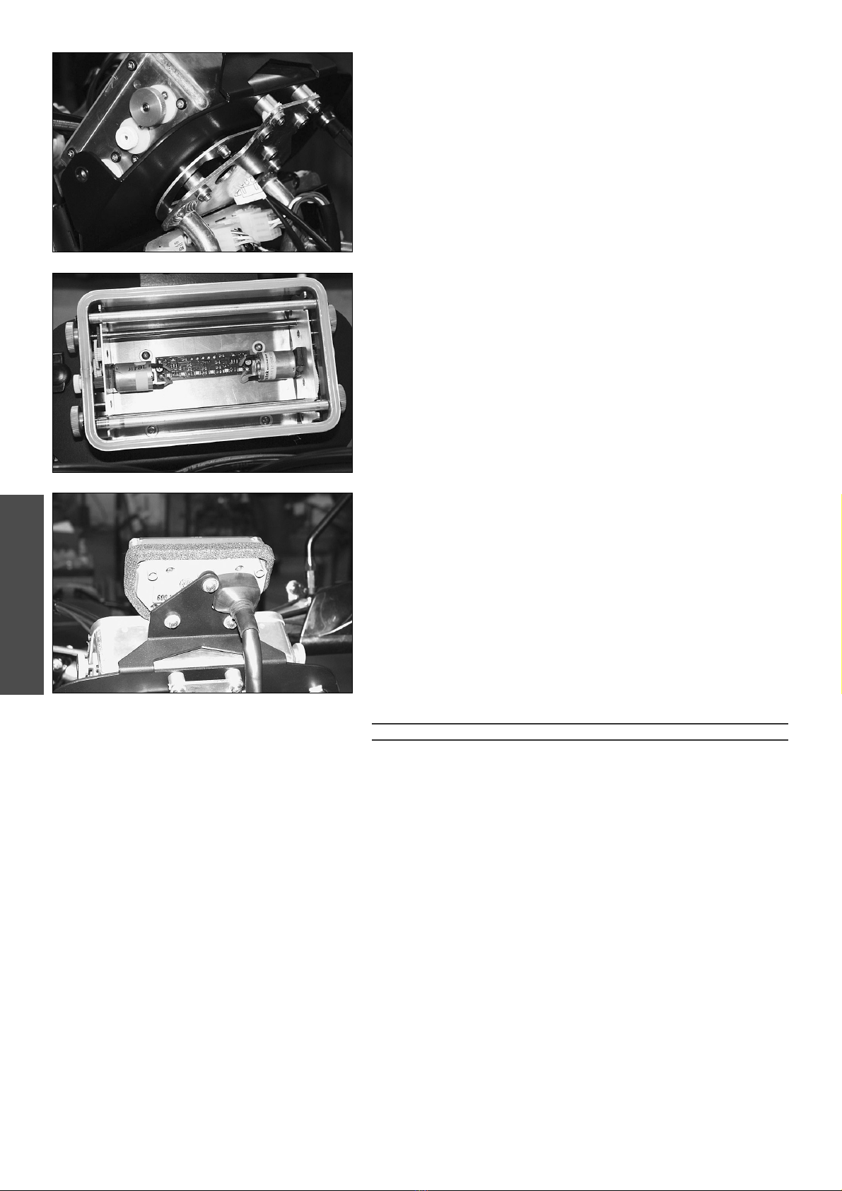
Lösen Sie nun die Verschraubungen und Anschlussstecker von Tripmaster
und Drehzahlmesser und entfernen Sie diese. Entfernen Sie nun den origi-
nalen Tripmaster- und Drehzahlmesserhalter 3.
HINWEIS:
Der Drehzahlmesser kann bei der Montage des Roadbookkits nicht mehr
montiert werden.
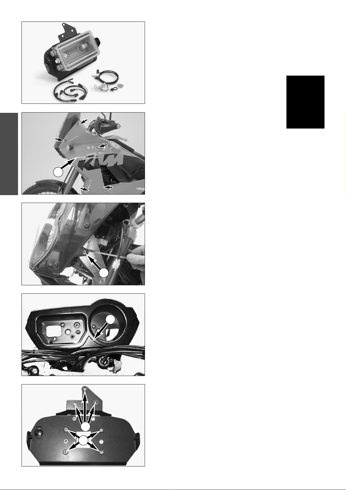
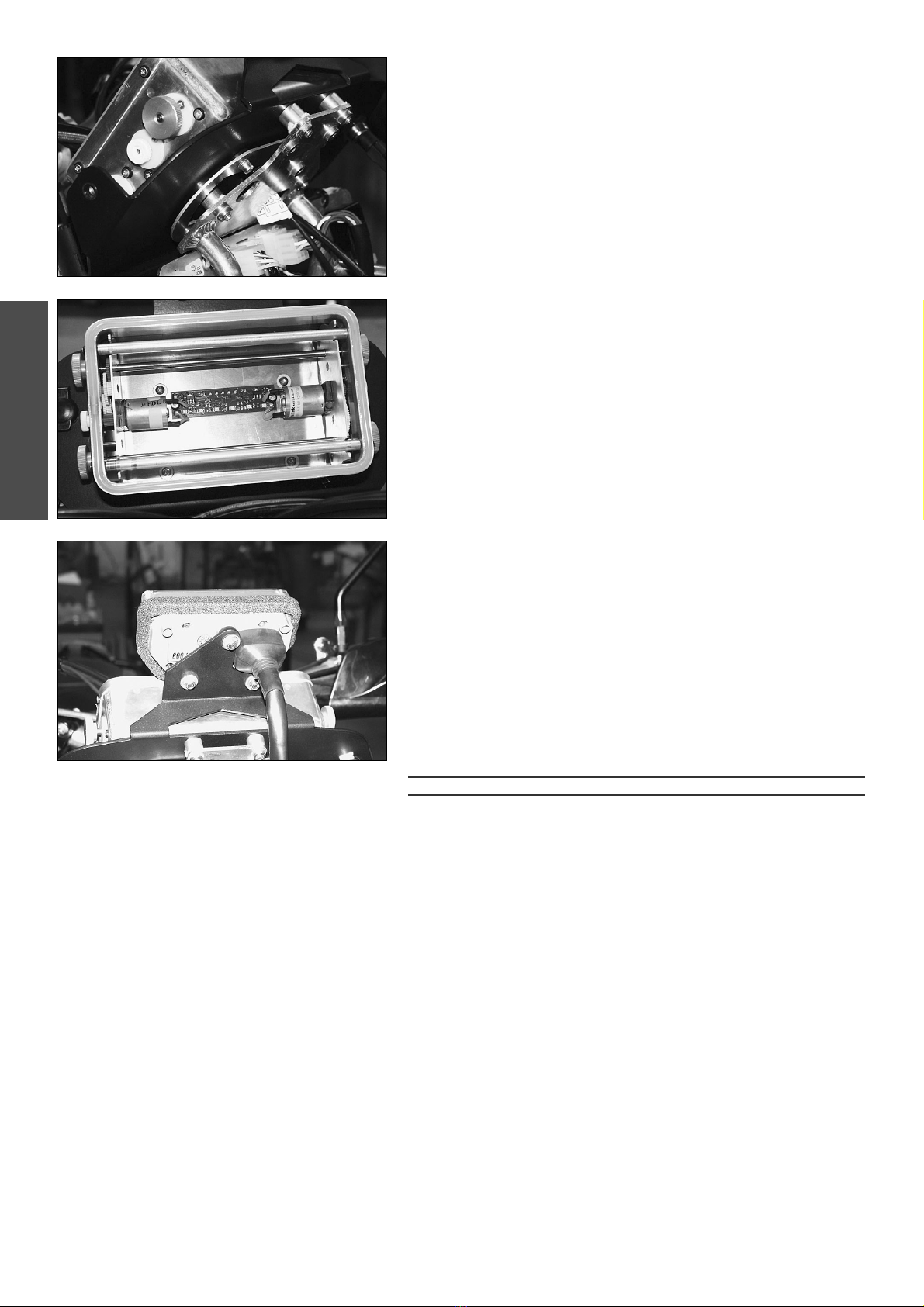
Vorbereitung der Roadbookmontageplatte
Entfernen Sie aus dem original Halter die Gummielemente des Tripmasters
und montieren Sie diese in die oberen drei Löcher der Roadbookmontage-
platte 4. Die Bordnetzsteckdose links in die Montageplatte einsetzen und
von hinten mit der beiliegenden Mutter verschrauben.
Die vier mitgelieferten Gummielemente in die nicht angesenkten Bohrungen
der Montageplatte montieren und jeweils eine Kunststoffbuchse einschieben 5.
In die angesenkten Bohrungen jeweils eine M6 Senkkopfschraube ein-
stecken und von hinten jeweilseine Kunststoffdistanz auf die Schrauben
schieben. Die Bohrungen der Distanzen sind leicht konisch, dies erleichtert
später die Montage.
4
5
1
2
3

DEUTSCH
3
Verschrauben Sie nun die Montageplatte mit den M6 Senkkopfschrauben
und Distanzen auf dem original Instrumentenhalter.
Die Lenkerfernbedienung 6des Roadbooks neben der Befestigungsschelle
des Kupplungshebels mit der beiliegenden Schelle und Montagematerial so
anschrauben, dass der Schalter sich vertikal bedienen läst.
Die Kabelverlegung sollte parallel zum Kupplungs- und Choke-Zug, dem
Vorbau entlang zum Steckerbord und dann weiter durch die Öffnung in der
Montageplatte geführt werden.
Vor dem Anschluss der elektrischen Komponenten an die Bordelektrik die
Sicherungen am Sicherungsträger mit der Bezeichnung ACC1 und ACC2
entfernen! Der Sicherungshalter befindet sich im vorderen Staufach vor der
Sitzbank.
Anschluss an die Bordelektrik
Im rechten Bereich des Instrumententrägers finden Sie zwei braune, ein
schwarz/rotes und ein rot/gelbes Kabel. Schließen Sie die Kabel wie folgt
an:
Kabelsatz für Anschluss von Roadbookhalter RB-TT:
Schwarz - schwarz-rot
Braun - braun
Kabelsatz für Anschluss von Steckdose:
Gelb - rot-gelb
Braun - braun
HINWEIS:
Je ein Stecker braun und gelb und je ein Stecker schwarz und braun bleibt
für zusätzliche Anwendungen frei.
Legen Sie den Kabelstrang mit dem gelben und dem braunen Kabel (Kabel-
satz für Anschluss von Steckdose) zur Bordnetzsteckdose. Schließen Sie die
Kabel an die Steckdose an. Achten Sie darauf, dass das braune Kabel
(Masse) am seitlichen Stecker anzuschließen ist, und das gelbe (+12V) am
mittig gelegenen.
Den Kabelstrang mit dem schwarzen und dem braunen Kabel entlang dem
Instrumententräger durch die Montageplatte führen.
6

DEUTSCH
Die Stecker für die Fernbedienung und für den 12-Volt-Anschluss am Road-
book anschließen und das Roadbook mit vier M5 Linsenkopfschrauben und
Unterlegscheiben durch die vier Gummielemente hindurch mit der mitgelie-
ferten Mutternplatte verschrauben.
4
Anschließend den original Tripmaster in den original Gummielementen
montieren und wieder anschließen.
Alle Kabel mit Kabelbindern fixieren, Sicherungen wieder einsetzten und
Roadbookhalter, Fernbedienung und Steckdose auf Funktion prüfen. Road-
bookhalter darf nur bei eingeschalteter Zündung funktionieren, Steckdose
auch wenn die Zündung aus ist.
Scheinwerfer, Seitenverkleidung und Windschild wieder montieren. Die
Stecker für die Blinker ebenfalls wieder anschließen. Die Freigängigkeit der
Lenkung prüfen.
ACHTUNG
DIE BEDIENUNG DER ROADBOOKFERNBEDIENUNG UND DAS ABLESEN VON INFORMATIO-
NEN AUF DEM ROADBOOK SELBST, SOLLTEN IMMER BEI ANGEHALTENEM MOTORRAD
ERFOLGEN. WENN SIE DIESE TÄTIGKEITEN WÄHREND DER FAHRT VORNEHMEN, WERDEN
SIE VON DER STRASSE UND VOM VERKEHR ABGELENKT. DABEI KANN ES LEICHT ZU
UNFÄLLEN KOMMEN.

Scope of supply
1 x RB-TT road book holder 600.12.073.000
1 x mounting plate 600.12.073.050
1 x handlebar remote control with wiring harness and
mounting material 600.12.073.080
1 x DIN on-board 12V power outlet, covered 600.11.042.000
1 x wiring harness to connect the socket 600.11.042.050
1 x wiring harness to connect the RB-TT road book holder 600.12.073.060
4 x M5 oval head screw 600.12.073.070
2 x M6x25 flat-head screw
2 x M6x30 flat head screws
4 x plastic spacer
4 x rubber element
4 x plastic sleeve
1 x 4xM5 motherboard
2 x M6 nuts
2 x M6 shims
Mounting
Loosen the 5 fixing screws on the left and right and remove both side cover 1.
ENGLISH
5
Detach the retaining tab 2with a screwdriver, tilt the windshield and
headlight forwards and pull the connector from the connector support.
Loosen the screw connections and connectors on the trip master and tacho-
meter and remove. Now remove the original trip master and tachometer
holder 3.
NOTE:
The tachometer cannot be mounted if the road book kit is mounted.
Preparing the road book mounting plate
Remove the rubber elements from the original trip master holder and
mount them in the upper three holes in the road book mounting plate 4.
Insert the on-board power outlet in the left part of the mounting plate and
fasten from behind with the nut included in the scope of supply.
Mount the four rubber elements included in the scope of supply in holes in
the mounting plate that are not countersunk and insert a plastic sleeve in
each element 5.
Insert one M6 flat-head screw in each countersunk hole and slip a plastic
spacer on each screw from behind. The holes in the spacers are slightly
conical to facilitate the mounting.
4
5
1
2
3

ENGLISH
6
Screw the mounting plate with the M6 flat-head screws and spacers to the
original instrument mount.
Screw the handlebar remote control 6for the road book next to the fixing
clamp on the clutch lever with the clamp and mounting material included in
the scope of supply to allow the switch to be actuated in a vertical position.
Run the cables parallel to the clutch and choke cable, along the front end to
the connector support and then through the opening in the mounting plate.
Before connecting the electric components to the electric system, remove
the fuses from the fuse holders marked ACC1 and ACC2. The fuse holder is
located in the front storage box in front of the seat.
Connection to the electric system
Two brown, one black/red and one red/yellow cable are located in the right
part of the instrument mount. Connect the cables as follows:
Cable harness to connect the road book holder RB-TT:
Black - black-red
Brown - brown
Cable harness to connect the socket:
Yellow - red-yellow
Brown - brown
NOTE:
1 brown and yellow connector and 1 black and brown connector will be
available for other applications.
Run the wiring harness with the yellow and brown cables (wiring harness to
connect the socket) to the on-board power outlet. Connect the cable to the
socket. Make sure the brown cable (ground) is connected to the side
connector and the yellow cable (+12V) to the center connector.
Run the wiring harness with the black and brown cables along the instru-
ment mount and through the mounting plate.
6

ENGLISH
7
Connect the connectors for the remote control and for the 12-volt connec-
tion to the road book and use the four M5 oval head screws and washers to
screw the road book through the four rubber elements to the motherboard
included in the scope of supply.
Now mount the original trip master in the original rubber elements and
reconnect.
Fix all cables with cable clips, reinsert the fuses and check the road book
holder, the remote control and the socket for proper functioning. The road
book holder should only operate when the ignition is switched on, the
socket should also function when the ignition is switched off.
Mount the headlight, side covers and windshield again. Connect the
connectors for the turn signal. Check the steering for free movement.
WARNING
ALWAYS STOP THE MOTORCYCLE TO OPERATE THE ROAD BOOK REMOTE CONTROL OR
TO READ THE INFORMATION IN THE ROAD BOOK ITSELF. IFYOU DO THIS WHILE DRIVING,
YOUR ATTENTION WILL BE DISTRACTED FROM THE TRAFFIC AND IT MAY CAUSE YOU TO
HAVE AN ACCIDENT.

Volume della fornitura
1 x porta road book RB-TT 600.12.073.000
1 x piastra di montaggio 600.12.073.050
1 x telecomando da manubrio con cavi e kit
di fissaggio 600.12.073.080
1 x presa di bordo DIN 12V coperta 600.11.042.000
1 x cablaggio per connessione presa di bordo 600.11.042.050
1 x cablaggio per connessione porta road book RB-TT 600.12.073.060
4 x vite a testa bombata M5 600.12.073.070
2 x vite a testa svasata M6x25
2 x vite a testa svasata M6x30
4 x distanziali in plastica
4 x elementi in gomma
4 x boccola in plastica
1 x piastra forata per dadi 4xM5
2 x dado M6
2 x rondella M6
Montaggio
Svitare a destra ed a sinistra le cinque viti di fissaggio e togliere i due rivesti-
menti laterali 1.
ITALIANO
8
Con un cacciavite sganciare la linguetta di fissaggio 2ribaltare in avanti lo
schermo completo di doppiofaro e staccare il connettore dal pannello di
connessione.
Svitare le viti e staccare i connettori del tripmaster e del contagiri e toglierli.
Togliere il supporto originale del tripmaster e del contagiri 3.
AVVERTENZA:
In caso di montaggio del porta road book il contagiri non può più essere
montato.
Preparazione piastra di montaggio road book
Togliere dal supporto originale gli elementi in gomma del tripmaster e mon-
tarli nei tre fori superiori della piastra di montaggio road book 4. Inserire la
presa di bordo a sinistra nella piastra di montaggio ed avvitarla da dietro
con il dado incluso.
Montare i quattro elementi in gomma inclusi nel kit nei fori non svasati della
piastra di montaggio ed inserirvi rispettivamente una boccola in plastica 5.
Nei fori svasati inserire rispettivamente una vite a testa svasata M6 e da die-
tro infilare sulle viti rispettivamente un distanziale in plastica. I fori dei
distanziali sono leggermente conici per facilitare il montaggio.
4
5
1
2
3

ITALIANO
9
Ora avvitare la piastra di montaggio con le viti a testa svasata M6 ed i
distanziali sul portastrumenti originale.
Con la fascetta ed il materiale di montaggio inclusi nel kit avvitare il teleco-
mando da manubrio 6del road book a fianco della fascetta di fissaggio
della leva frizione in modo tale che l'azionamento dell'interruttore avvenga
in senso verticale.
I relativi cavi dovrebbero essere sistemati parallelamente al cavo frizione ed
al cavo dell'aria fino al pannello di connessione e poi guidati attraverso l'a-
pertura nella piastra di montaggio.
Prima di connettere i componenti elettrici all'impianto elettrico di bordo,
rimuovere i fusibili con la scritta ACC1 ed ACC2 dalla scatola fusibili! La sca-
tola fusibili si trova nel vano portaoggetti anteriore davanti la sella.
Connessione all'impianto elettrico di bordo
Nella zona destra del portastrumenti si trovano due cavi marrone, un cavo
nero/rosso ed un cavo rosso/giallo. Collegare i cavi come segue:
cablaggio per connessione porta road book RB-TT:
nero - nero-rosso
marrone - marrone
cablaggio per connessione presa di bordo:
giallo - rosso-giallo
marrone - marrone
AVVERTENZA:
Rispettivamente un connettore marrone ed uno giallo e rispettivamente un
connettore nero ed uno marrone rimangono liberi per altre applicazioni.
Sistemare il cablaggio con i cavi color giallo e marrone (cablaggio per conn-
essione presa di bordo) fino alla presa di bordo. Collegare i cavi alla presa.
Far attenzione a collegare il cavo marrone (massa) al connettore laterale, e
quello giallo (+12V) al connettore in posizione centrale.
Guidare il cablaggio con i cavi color nero e marrone lungo il portastrumenti
ed attraverso la piastra di montaggio.
6

ITALIANO
Collegare i connettori per il telecomando e per la connessione a 12 volt al
road book ed avvitare quest'ultimo con le quattro viti a testa bombata M5 e
le rondelle attraverso i quattro elementi in gomma con la piastra forata
inclusa nel kit.
10
Dopodiché montare il tripmaster originale negli elementi originali in gomma
e collegarlo.
Fissare tutti i cavi con fascette serracavi, reinserire i fusibili e controllare il
funzionamento del porta road book, del telecomando e della presa di
bordo. Il porta road book deve funzionare solo ad accensione inserita e la
presa di bordo anche ad accensione disinserita.
Rimontare il doppiofaro, i rivestimenti laterali e lo schermo. Ricollegare
anche i connettori degli indicatori di direzione. Infine controllare la scorrevo-
lezza dello sterzo.
ATTENZIONE
L'AZIONAMENTO DEL TELECOMANDO DEL ROAD BOOK E LA LETTURA DI INFORMAZIONI
SUL ROAD BOOK STESSO DOVREBBERO AVVENIRE SEMPRE A MOTOCICLETTA FERMA. SE
ESEGUITE QUESTE OPERAZIONI DURANTE LA GUIDA, SARETE DISTOLTI DALLA STRADA E DAL
TRAFFICO. DICONSEGUENZA È ANCHE FACILE CHE SI VERIFICHINO DEGLI INCIDENTI.

Kit de montage
1 x dévideur de roadbook RB-TT 600.12.073.000
1 x plaque de montage 600.12.073.050
1 x commande au guidon avec faisceau et petites fournitures
600 12 073.080
1 x prise 12 V DIN avec couvercle 600.11.042.000
1 x faisceau de raccordement de la prise 600.11.042.050
1 x faisceau de raccordement du dévideur RB-TT 600.12.073.060
4 x vis à tête bombée M5 600.12.073.070
2 x vis à tête noyée M6x25
2 x vis à tête noyée M6x30
4 x entretoises en plastique
4 x caoutchoucs
4 x douilles en plastique
1 x plaque avec écrous 4xM5
2 x écrous M6
2 x rondelles M6
Montage
Enlever d’abord à droite et à gauche les 5 vis de fixation et déposer les
flancs de carénage 1.
FRANCAIS
11
Avec un tournevis décrocher la patte de fixation 2et basculer vers l’avant
le saute-vent avec le phare. Débrancher la prise sur la platine.
Enlever les fixations et les prises de raccordement du tripmaster et du
compte-tours et retirer ces derniers. Retirer les fixations d’origine des sup-
ports de tripmaster et de compte-tours 3.
NOTA BENE:
Quand on monte le kit roadbook il n’est plus possible de mettre le compte-
tours.
Préparation de la plaque de montage du roadbook
Retirer du support d’origine les caoutchoucs du tripmaster et les mettre
dans les trois trous du haut de la plaque de montage du roadbook 4.
Mettre en place la prise à gauche sur la plaque et la fixer par derrière avec
l’écrou qui est livré avec elle.
Mettre en place dans les trous non fraisés de la plaque les quatre caout-
choucs livrés et enfiler dedans les douilles en plastique 5.
Enfiler dans chaque trou fraisé une vis M6 à tête noyée et enfiler par l’autre
côté, sur la vis, une entretoise en plastique. Les perçages dans les entretoi-
ses sont légèrement coniques, ce qui facilite la suite du montage.
4
5
1
2
3

FRANCAIS
12
Fixer la plaque de montage avec les vis M6 à tête noyée et les entretoises
sur le support d’origine.
Fixer sur le guidon, à côté de la cocotte d’embrayage, la commande à
distance 6pour le roadbook. On utilise pour cela le collier qui est livré ainsi
que les petites fournitures. Le bouton doit pouvoir être actionné verticale-
ment.
La disposition du faisceau se fait parallèlement aux câbles d’embrayage et
de starter, puis vers la platine avec les prises et enfin à travers le trou de la
plaque de montage.
Avant de raccorder au circuit électrique il faut enlever les fusibles repérés
ACC1 et ACC2 dans la boîte à fusibles. Celle-ci se trouve dans le vide-
poche devant la selle.
Raccordement au circuit électrique
A droite du support se trouvent deux fils marrons, un fil rouge/noir et un fil
rouge/jaune. Raccorder les fils comme suit :
Faisceau de raccordement du dévideur de roadbook RB-TT :
noir rouge/noir
marron marron
Faisceau de raccordement de la prise :
jaune rouge/jaune
marron marron
NOTA BENE:
Quatre cosses restent libres pour une autre utilisation : marron et jaune ainsi
que noir et marron.
Mettre en place le faisceau avec le fil jaune et le fil marron (faisceau de rac-
cordement de la prise). Raccorder à la prise. Faire attention à raccorder le fil
marron (masse) à la cosse sur le côté et le fil jaune ( + 12 V) à la cosse du
milieu.
Mettre en place le faisceau avec le fil noir et le fil marron le long du support
et faire passer à travers la plaque de montage.
6

FRANCAIS
13
Brancher les cosses pour la commande à distance et le raccordement 12 V
sur le roadbook. Fixer le roadbook en utilisant les quatre vis M5 à tête bom-
bée, les rondelles, les quatre caoutchoucs et la plaque à écrous.
Monter ensuite le tripmaster d’origine sur les caoutchoucs d’origine et le
raccorder.
Fixer tous les fils avec des colliers, remettre les fusibles et vérifier si le dévi-
deur de roadbook, la prise et la commande à distance fonctionnent. Le
dévideur de roadbook doit fonctionner seulement quand l’allumage est mis.
La prise fonctionne aussi quand l’allumage est coupé. Reposer le phare, les
flancs de carénage et le saute-vent. Rebrancher les prises de raccordement
des clignotants. Vérifier si le guidon n’est pas bridé.
ATTENTION
ILFAUDRAIT TOUJOURS S’ARRÊTER POUR ACTIONNER LA COMMANDE À DISTANCE DU
ROADBOOK OU POUR LIRE LES INFORMATIONS DE CELUI-CI. SIONLEFAIT EN ROULANT,
ON PORTE MOINS D’ATTENTION À LA ROUTE ET À LA CIRCULATION, CE QUI PEUT FACILE-
MENT ENTRAÎNER UN ACCIDENT.
Table of contents
Languages:
Other KTM Motorcycle Accessories manuals

KTM
KTM 79602979044 Owner's manual

KTM
KTM 61712978000 User manual

KTM
KTM 78111994000 Owner's manual

KTM
KTM 90.06.019.000 User manual

KTM
KTM 90112927044 Owner's manual

KTM
KTM 45412955044S User manual

KTM
KTM 60112092010 Owner's manual

KTM
KTM 69130985044 Owner's manual

KTM
KTM 79610917000EB User manual

KTM
KTM PowerParts 55011599000 User manual

KTM
KTM 125 SX 2008 Guide

KTM
KTM 90111942044 Owner's manual

KTM
KTM 64108915044 Owner's manual

KTM
KTM 60112927044 Quick setup guide

KTM
KTM 60112929050 Owner's manual

KTM
KTM FAHRGESTELL 400/620 Guide

KTM
KTM 60712933050 Owner's manual

KTM
KTM 60435940044 User manual

KTM
KTM 76112912044C1 User manual

KTM
KTM 61307908000 Owner's manual