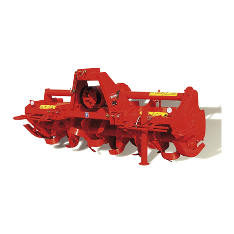
KUHN EL 62 User manual

ASSEMBLY/OPERATOR'SMANUAL
POWER TILLER EL 62 - EL 62 D
N° 95463 C.GB - 11.2003

DEAR OWNER,
In buying a KUHN machine you have chosen wisely. Into it have gone years of thought,
researchandimprovements.Youwillfind,ashavethousandsofownersallovertheworld,that
you have the best that engineering skill and actual field testing can produce. You have
purchased a dependable machine, but only by proper care and operation can you expect to
receive the performance and long service built into it.
This manual contains all the necessary information for you to receive full efficiency from your
machine.Theperformanceyougetfromthismachineislargelydependantuponhowwellyou
readandunderstandthismanualandapplythisknowledge.PleaseDONOTASSUMETHAT
YOU KNOW HOW TO OPERATE AND MAINTAIN YOUR MACHINE before reading this
manual carefully. KEEP THIS MANUAL AVAILABLE FOR REFERENCE.
YourKUHN dealerwillinstruct youonthegeneral operationofyourmachine. Heisinterested
that you get the best performance possible and will be glad to answer any special questions
that may arise regarding the operation of the KUHN machine.
Your KUHN dealer can offer a complete line of genuine KUHN service parts.
These parts are manufactured and carefully inspected in the same factory that builds the
machine to assure high quality and accurate fitting of any necessary replacements.
When ordering service parts it is important that you indicate the type of machine concerned
and its serial number.
Forthisreasonpleasecompletethemodelidentificationplatediagrambelowwiththerequired
information. This will provide you with an easy reference for future service parts orders.
ABOUT IMPROVEMENTS
KUHN iscontinuallystriving to improveitsproducts and,therefore,reserves the righttomake
improvements or changes when it becomes practical to do so, without incurring any
obligations to make changes or additions to the equipment sold previously.

- 1 -
CONTENTS
Page
Safety 2
Safety decals - Model identification plate 8
Technical specifications 10
Off-setting 11
Fitting to the tractor 12
P.T.O. shaft 14
Slip clutch 16
Rotorspeed 17
Hood 18
Use 18
Completionequipment 19
Optionalequipment 21
Maintenance 22
1. Lubrication 22
2. Fitting blades 23
Troubleshooting 24
Conditions of limited warranty 26
Copyright2003 KUHN S.A.

- 2 -
SAFETY
The above symbol is used throughout this manual every time recommendations are made concerning your
safety, the safety of others, or the good operation of the machine.
These recommendations must be made known to all machine operators.
DESIGNATED USE OF THE MACHINE
The EL 62 and EL 62 D must only be used for the work for which they have been designed :
- Gardening - market gardening
- For nurseries, landscaping and horticulture.
- Maintenance of private or public green spaces
- Lawn seedbed preparation
- Light operation in vineyards.
The manufacturer is not held liable for any damage resulting from machine applications other than those
specified by the manufacturer.
Any use other than the designated operation is at the risk and responsibility of the operator.
Designated use of the machine also means :
- following operation, maintenance and repair recommendations given by the manufacturer ;
- using only genuine spare parts, equipment and accessories as designated by the manufacturer.
TheEL 62 and EL 62 Dmustonly be operated,maintained and repairedby competent personswho are familiar
with machine specifications and operations and are aware of any danger involved.
The operator must imperatively respect current legislation concerning :
- accident prevention,
- work safety,
- public traffic circulation.
All safety advice indicated on the machine must be strictly observed.
The manufacturer is not held liable for any damage resulting from machine modifications carried out by the
operator himself or by a third party without previous written agreement from the manufacturer.

- 3 -
GENERAL SAFETY RECOMMENDATIONS
Before operating the machine, always ensure that tractor and machine are in accordance with work safety and
road traffic regulations.
BASICPRINCIPLES
1. Inadditiontotherecommendationsgiveninthismanual,legislationonworksafetyandaccidentprevention
must also be respected.
2. Advice is indicated on the machine, specifying safety recommendations in order to prevent accidents.
3. Before travelling on public roads, the operator must ensure that the machine conforms to road traffic
regulations.
4. Before starting work, the operator must be familiar with all machine controls, handling devices and their
functions. Once at work, it is too late to do so !
5. Useatractorequippedwithasafetycab.Keepwindowsandroofhatchclosedforreducedsoundlevelwhile
operating the PTO driven implement.
6. Beforestartingupthemachineandbeginningwork,checkthesurroundingarea(bewareofchildren!).Make
sure there is sufficient visibility.
Keep all people and animals away from the danger zone of the machine (risk of projection !)
7. Carrying people or animals on the machine when working or in transport is strictly forbidden.
8. Machine must only be attached to tractor using means provided and in accordance with current safety
standards.
9. Special care should be taken when attaching or removing the machine from the tractor.
10. Before attaching the machine, ensure that the front tractor axle is sufficiently ballasted.
Ballastis to be placedonthesupportsprovidedinaccordancewith instructions of thetractormanufacturer.
11. Do not surpass the maximum axle load or the overall transport weight as prescribed by the tractor
manufacturer.
12. Do not surpass the maximum transport width authorized by road traffic regulations.
13. Before transporting the machine on public roads, ensure that all legally required guards and indicators
(lights, reflectors ...) are in place and in good operation.
14. All operating controls (cords, cables, rods...) must be positioned so that they cannot be set off accidently,
risking accident or damage.
15. Before transporting on public roads, locate the machine into its transport position as instructed in this
operator’s manual.
16. Never leave the tractor seat while the machine is operating.

- 4 -
17. Drive speed must be adapted to ground conditions as well as roads and paths.
Always avoid abrupt changes of direction.
18. Precision steering, tractor adherence, road holding and efficient braking are influenced by the type of
implement, weight, ballast of front axle, ground or road conditions. It is therefore of utmost importance to
be cautious in every given situation.
19. Be particularly cautious when turning corners, paying attention to machine overhang, length, height and
weight.
20. Keep clear of the machine operating area.
21. WARNING ! Danger of crushing and shearing can exist when components are operated by hydraulic or
pneumatic controls.
22. Before leaving the tractor or before adjusting, maintaining or repairing the machine, turn off the engine,
remove ignition key and wait until all moving parts have come to a complete stop.
23. Do not stand between the tractor and the machine unless the hand brake is tight and/or stops have been
placed under the wheels.
24. Beforeanyadjustments,maintenanceorrepairsarecarriedout,ensurethatthemachinecannotbestarted
up accidentally.
PRECAUTIONS TO BE TAKEN BEFORE OPERATING THE MACHINE
1. Do not wear loose clothing which could become caught up in moving elements.
2. Wear the individual protection equipment corresponding to the work which is planned (gloves, shoes, eye
protection, helmet, ear protectors...).
3. All operating controls (cords, cables, rods ...) must be positioned so that they cannot be set off accidentally,
causing accident or damage.
4. Before operating the machine, check the tightness of all nuts and bolts, particularly on rotating parts (blades,
tines, knives, spades ...)
5. Before operating the machine, ensure that all safety guards are firmly in place and in good condition. If worn
or damaged, replace immediately.
ATTACHMENT
1. When attaching or removing the machine from the tractor, position hydraulic lift control lever in such a way
that it cannot be set off accidentally.
2. When attaching the machine to tractor hydraulic linkage, ensure that diameter of link pins corresponds to
diameter of ball joints.
3. WARNING ! Danger of crushing and shearing can exist in the lifting zone of the tractor hydraulic linkage !
4. Donotstandbetweenthetractorandthemachinewhenoperatingtheoutercontrolleveroftheliftmechanism.
5. In transport, the machine lift mechanism should be stabilized by tractor tie rods to avoid floatation and side
shifting.
6. When transporting machine ensure that it can not be lowered accidentally.
- 5 -
POWER TAKE-OFF
1. Use only the PTO shaft supplied with the machine or recommended by the manufacturer.
2. PTO guards must always be in place and in good condition.
3. Check for correct PTO overlap when at work and in transport.
4. Before attachingor removing thePTO shaft,disengagePTO shaft,turn off engineand remove ignitionkey.
5. If a primary PTO shaft is equipped with a slip clutch or a free wheel, these must be fitted on the machine
PTO.
6. Ensure that PTO shaft is always correctly fitted and locked into place.
7. Make sure guards are correctly in place and secured with the safety chains provided.
8. Before engaging PTO, ensure that PTO speed (rotational frequency) and direction are in accordance with
manufacturer's recommendations.
9. Before engaging PTO, keep all people and animals clear from the machine.
10. Never engage PTO shaft when tractor engine is turned off.
11. Never surpass the PTO angle recommended by the manufacturer.
12. WARNING!Rotating elements cancontinueturning momentarily after PTOisdisengaged. Keep clear until
all rotating elements are at a standstill.
13. When removing the machine, place PTO shaft on the supports provided.
14. Fit the safety cap on tractor PTO.
15. Replace any worn or damaged PTO guards immediately.
Rotation speed ... rpm (American Measure) is also expressed in metric measure : Rotational frequency ... min-1.
Both units are equivalent, for example : Rotation speed 540 rpm equals Rotational frequency 540 min-1.

- 6 -
MAINTENANCE
1. Before checking for any machine malfunction and before adjusting, maintaining or repairing the machine,
disengage PTO, turn off engine and remove ignition key.
2. Check nut and bolt tightness regularly. Retighten if necessary.
3. If the machine is raised, prop it up in a stable position before carrying out any maintenance work.
4. When replacing a working part, wear protection gloves and use only standardized tools.
5. It is forbidden to discard any oil, grease or filters. These must be given to waste disposal organisations to
protect the environment.
6. Disconnect power source before any work is done to the electric system.
7. Check safetyguards regularly, particularlythose that aresubject to wear.Replaceimmediately if damaged.
8. Spare parts used must be in accordance with specifications and standards as defined by the manufacturer.
Use only genuine KUHN parts !
9. Before any electric welding is carried out on tractor or attached machine, disconnect generator and battery
terminals.
10. Repairs on elements under pressure or tension (springs, accumulators etc...) must only be carried out by
competent persons with standardized equipment.

- 7 -
- N o t e s -

- 8 -
The following safety pictorials have been placed on your machine in the areas indicated.
They are intented for your personal safety and for the safety of the people working with
you. The text shown on them gives their precise meaning. Keep the pictorials clean. Re-
place them when they are faded.
SAFETY DECALS
MODEL IDENTIFICATION PLATE

- 9 -
1
2
3
4
7
6
5

- 10 -
TECHNICAL SPECIFICATIONS
SINGLESPEEDGEARBOX DUPLEXGEARBOX
EL 62 EL 62 EL 62 EL 62 EL 62 EL 62 D EL 62 D EL 62 D EL 62 D
130 155 165 180 210 130 165 180 210
Workingwidth cm (") 128(4'2") 153(5') 165(5'5") 178 (5'10") 210(6'11") 128 (4'2") 165(5'5") 178 (5'10") 210(6'11")
Maximum allowable engine (DIN) power kW (hp) DIN48(65) DIN48(65)
Minimumpowerrequirement kW (hp) 19(25) 22(30) 24(33) 26(35) 31(42) 19(25) 24(33) 26(35) 31(42)
P.T.O.speed rpm(min-1)540 540
Rotorspeed rpm(min-1)224 206or245
Rotordiameter mm (") 450(1'6") 450(1'6")
Numberofblades(3pairformation) 30 36 42 42 54 30 42 42 54
Working depth mini / maxi mm (") 50 / 180 50 / 180
Workingdepthcontrol Gaugewheels or skids Gaugewheels or skids
P.T.O.shaft with friction slip clutch with friction slip clutch
Off-settingto theright mm (")
(for single speed models) 200 (8") 200 (8") 200 (8") 200 (8") - - - - -
Attachment Cat. 1 N (narrow) - 1 and 2 Cat. 1 N (narrow) - 1 and 2
Totalwidth
- with skids cm (") 145(4'9") 170(5'7") 181(5'11") 194(6'4") 227(7'5") 145 (4'9") 181(5'11") 194(6'4") 227(7'5")
-withgauge wheels cm (") 139 (4'7") 164 (5'6") 176 (5'9") 188 (6'2") 220 (7'3") 139 (4'7") 176 (5'9") 188 (6'2") 220 (7'3")
Weight with skids + parking stand
(withPTOshaft) kg (lbs) 295 (649) 330 (726) 360 (792) 365 (803) 420 (924) 316 (695) 382 (840) 390 (858) 445 (979)
Weightwithgaugewheels (with PTO shaft) kg (lbs) 295 (649) 330 (726) 360 (792) 365 (803) 420 (924) 316 (695) 382 (840) 390 (858) 445 (979)
TECHNICAL SPECIFICATIONS

- 11 -
OFF-SETTING
(only for single speed models 130 / 155 / 165 / 180)
TheEL 62power tillerswithsingle speedgearboxand aworkingwidth of130- 155-165 -180 canbeoffset
to the right of the tractor centre line.
When the working conditions require the offsetting of the machine, it must be carried out before attaching the
machine to the tractor. Make sure the machine is resting on the ground and stabilised with its parking stand or
wheels.
The offset is made by sliding the lower hitch pins (A) on the front tube (T) and the upper hitch pin (B) on hitch
frame tube (S) (photos 2, 3 and 4). Then tighten nuts (E) on hitch pin (A and B) to 21 daNm/ 155 ft.lbs.
The machine may be offset by a maximum of 20 cm (8") with regards to the axial position.
4
2
3

- 12 -
FITTING TO THE TRACTOR
The EL 62 has two adjustment settings giving the following attachment possibilities :
CATEGORY "1 N" (NARROW) LINKAGE
CATEGORY "1" LINKAGE
5
6

- 13 -
CATEGORY "2" LINKAGE
7

- 14 -
8
P.T.O. DRIVE SHAFT
MakesuretheEL62andEL62Darerestingonthegroundandaremaintainedinastablepositionwiththeparking
standorwiththefrontwheels.CleanandlubricatethegearboxinputshaftandslidethematingPTOshaftyokein
place.
Aftermounting thePower Tiller, stabilize the tractor3-point linkagewith whatever means are recommended(tie
bars, chains etc.).
Be sure the tractor P.T.O. shaft drive is disengaged and stop engine.
Couple the PTO shaft to the tractor P.T.O. stub.
Attachment is correct when machine is horizontal in work position.
With the machine resting on the ground, adjust the top link (P) length to a position where the tractor PTO stub
and the tiller input shaft are parallel.
In working position :
- The 2 angles (K) formed by the centre lines of the yoke and the sliding tubes must be equal and not exceed
a combined angle of 30° when working.
- The sliding tube overlap (L) must be at least 22 cm (8.5") (fig. 8).

- 15 -
With the machine fully raised on the tractor hydraulic linkage :
- The 2 sliding tubes must not completely overlap each other ; a gap (M) of 1 cm (3/8") should exist between
end of sliding tube and yoke.
- Both U joints (K) should operate approximately at the same bent angles which must never exceed 40° (fig. 8).
Should the above mentioned conditions not exist :
- Shorten both tubes by an equal length, chamfer edges and grease liberally before refitting.
- To avoid noisy running of the PTO shaft when lifting the machine out of work, attach top link (P) so that it is
almost parallel to the lower links (fig. 8).
Important : Always disconnect the tractor PTO drive before lifting the machine into the transport position,
otherwise permanent damage can be caused to the transmission shaft.
Repeat these adjustments each time the machine is mounted to a different tractor.
Always make sure the PTO shaft guards are in good condition and secured with the
safety chains provided to prevent them from turning. On themachine side, attach safety
chain (S) to the front tube (F) (photo 9). All worn or damaged guards must be replaced
immediately.
A safety chain (C) is delivered with the machine to
support the PTO shaft (T) when the machine is
parked. This prevents the PTO shaft from becoming
soiledordeterioratedwhenincontactwiththeground.
Fit chain (C) on hitch frame tube (U) as shown
photo 9.
9

- 16 -
FRICTION SLIP CLUTCH
IMPORTANT: * Always check the clutch to see if it is set correctly. A clutch that is set properly will feel warm
to the touch, but not hot, during normal work. A slip clutch that is not warm to the touch after
normal work may have either the springs over tightened or seized discs. (See seasonal
maintenance below for instructions regarding seized discs).
* Never continue to operate the tiller if the clutch slips excessively. Increased disc wear and
damage to the clutch can occur. The following is a list of common causes and corrections for
a clutch slipping excessively :
Too light a spring pressure - readjust spring to proper length
Too much horsepower - use a tractor within allowable horsepower range
Excessive ground speed - decrease ground speed
Excessively hard soil - decrease tilling depth or ground speed
Obstacles - remove obstacles before tilling
* If the clutch has slipped excessively follow the corrections listed above then wait until the
temperature of the clutch drops to a normal work temperature of approximately 104°F (40°C)
before continuing work. An overheated clutch will slip more easily.
Seasonal maintenance : If the machine has not worked in a long time the slip clutch discs may seize together.
This prevents the slip clutch from functioning properly. To remedy this, proceed with the following :
1) With the tractor shut off and the tiller lowered to the ground, slacken off the 6 springs (R), figure 10, by
loosening their securing nuts.
2) Restart the tractor and with the engine at idle slowly engage the PTO. Let the clutch slip for a few seconds
then stop the PTO. Shut off the tractor. Retighten the springs to 1"1/12 (27,5 mm) as described above.
IMPORTANT : If the slip clutch does not slip, immediately disengage the PTO. If the slip clutch will not slip with
the springs slackened the slip clutch must be repaired by your authorised Kuhn dealer.
At no time should the tiller be operated on a tractor
rated at more than 48 kW (65 hp) engine DIN
power.Theslipclutchisproperlysetwhenusingthe
spring length (L), figure 10, for all 8 springs is set at
1"1/12(27,5mm).Allspringsmustbeadjustedequally.
Neveradjusttheslipclutchsothatthe
springlength(L)islessthanat1"1/12
(27.5 mm) or damage to the tiller will
result.
TheEL62andEL62Dareequippedwithaslipclutch(fig.10)toprotectthetillerfromtheexcessiveforcescaused
by rocks, hard soils, or incorrect operation. Proper adjustment and maintenance of the slip clutch is essential to
protectthetiller.
10

- 17 -
ROTOR SPEED (ROTATIONAL FREQUENCY)
1) "EL 62" single speed :
Therotorspeed(rotationalfrequency)ofthe"EL62"singlespeedis224rpm(min-1)withaP.T.O.speed(rotational
frequency)of540rpm (min-1).
NootherPTOspeed(rotationalfrequency)isallowed.
2) "EL 62 D" Duplex :
The "EL 62 D" Duplex is fitted with a gearbox which adapt the rotor speed (rotational frequency) to the working
conditions. It must be used with a PTO speed of 540 rpm (min-1)only.
TochangethePTOspeed(rotationalfrequency)invertthematchinggearwheelslocatedbehindthereargearbox
cover.
Toinvertthepinionsproceedasfollows.Tiltthemachineforwardtoavoidoilleakingoutofthegearboxwhenremoving
the cover. To do this :
- uncouplethePTOshaft
- shortenthe turn buckle
- raise the machine in order to obtain a satisfactory angle
- remove bolts (U) from cover plate (V) and pull the cover out of the gearbox (photo A),
- invert the matching gears (E and F), according to the desired rotor speed (rotational frequency) (photo B),
- reinstall the cover plate making sure to position the seal (G) (photo B) correctly on the cover (photo B)
(torque to 5 daNm / 37 ft.lbs).
AB
Rotor speed (rotational frequency) chart "EL 62 D" Duplex in rpm (min-1) :
*
540 rpm (min-1) 206 245
Positionof
gears
P.T.O.speed
(rotationalfrequency)
24 22 22 24
*Ex-Works setting

- 18 -
USE
Before carrying out any operation on the machine, stop the tractor engine,
remove ignition key and wait for all rotating parts to stop before leaving the
tractor.
The tilth varies with the work required. The degree of tilth is governed by combining the following factors :
- forward speed,
- working depth,
- hood position : adjusted by means of a selector lever and a multi-hole plate,
- mounting of 2 or 3 pairs of blades,
- number of passes.
Coarse tilth : - Rear shield up
- Fast forward speed (approx. 2.5 mph - 4 km/h)
- 2 pairs of blades
- Low rotor speed (206 rpm / min-1) for the EL 62 D Duplex.
Fine tilth : -Rearshielddown
- Slow forward speed (approx. 1.25 mph - 2 km/h)
- 3 pairs of blades
- High rotor speed (245 rpm / min-1) for the EL 62 D Duplex.
11
Thepositionofhood(G)canbeadjustedbymeansof
two selector levers (H) and two multi-hole plates (I)
(photo11).
Securehood(G)inthechosenpositionusinglockpins
(J) (photo 11).
For road transport, hood (G) must
be fully closed so that the reflec-
tors (K) are visible for other road
users (photo 11).
Hints on use :
- Allowtherotortorotateatistworkingspeedbeforeengagingitintothesoil.Graduallylowerthemachinewhile
pulling forward with the tractor.
- Always work in a straight line. When turning, lift machine out of work.
- Never work in reverse, otherwise damage could occur to some component parts.
- Do not disengage the PTO drive unless the machine has been lifted out of work.
Important remarks :
Like many farm machines, the use of the EL 62 entails limits which must be respected in all situations. These
limits are often tied in with :
- meteorological conditions : avoid working during and immediately after rainfall, wait until ground to be
worked is completely drained,
- soil types : smooth clods indicate too malleable or too humid soil to be worked in. Wait until ground is
completely drained. Soil consistency is ideal when clods crumble without sticking,
- tractor power : adapt share depth, working depth and forward speed to power available and type of work to
be done.
Never exceed the maximum allowable power : engine (DIN) 48 kW (65 hp).
HOOD
This manual suits for next models
1
Table of contents
Other KUHN Farm Equipment manuals
Popular Farm Equipment manuals by other brands

matev
matev MOW MM-152 Mounting

Gaspardo
Gaspardo COMBINATA 250 Use and maintenance / spare parts

Croplands
Croplands PEGASUS 4000 PARTS & OPERATORS MANUAL

Kverneland
Kverneland Optima TFprofi ll manual

Textron
Textron SODCUTTER 544847B Technical manual

Finn
Finn BARK BLOWER BB-1208 Parts and Operator's Manual

BSL
BSL Strautmann Verti-Mix 1101 SF fast-cut operating instructions

Ventrac
Ventrac Terra Rake KR502 Operator's manual & parts drawings

Kellfri
Kellfri 27-V18ATV manual

TATU
TATU 2240 GCRO instruction manual

red roo
red roo SHP400 Operation, Safety & Maintenance Instructions

AGRO-MASZ
AGRO-MASZ POV Series instruction manual