KUHN GMD 700 G II User manual

ASSEMBLY / OPERATOR'S MANUAL
GMD 600 G II / 700 G II / 800 G II
GMD 600 G II-HD / 700 G II-HD / 800 G II-HD
MULTIDISC MOWER
N° 95009 D.GB - 06.2006

DEAR OWNER,
In buying a KUHN machine you have chosen wisely. Into it have gone years of thought,
researchandimprovements.Youwillfind,ashavethousandsofownersallovertheworld,that
you have the best that engineering skill and actual field testing can produce. You have
purchased a dependable machine, but only by proper care and operation can you expect to
receive the performance and long service built into it.
This manual contains all the necessary information for you to receive full efficiency from your
machine.Theperformanceyougetfromthismachineislargelydependantuponhowwellyou
readandunderstandthismanualandapplythisknowledge.PleaseDONOTASSUMETHAT
YOU KNOW HOW TO OPERATE AND MAINTAIN YOUR MACHINE before reading this
manual carefully. KEEP THIS MANUAL AVAILABLE FOR REFERENCE.
YourKUHN dealerwillinstruct youonthegeneral operationofyourmachine. He isinterested
that you get the best performance possible and will be glad to answer any special questions
that may arise regarding the operation of the KUHN machine.
Your KUHN dealer can offer a complete line of genuine KUHN service parts.
These parts are manufactured and carefully inspected in the same factory that builds the
machine to assure high quality and accurate fitting of any necessary replacements.
When ordering service parts it is important that you indicate the type of machine concerned
and its serial number.
Forthisreasonpleasecompletethemodelidentificationplatediagrambelowwiththerequired
information. This will provide you with an easy reference for future service parts orders.
ABOUT IMPROVEMENTS
KUHN iscontinuallystriving to improveitsproducts and,therefore,reserves the righttomake
improvements or changes when it becomes practical to do so, without incurring any
obligations to make changes or additions to the equipment sold previously.

- 1 -
CONTENTS
Page
Safety 2
Safetydecals 8
Technicalspecifications 11
Assembly 11
Generalinformation 17
Adapting to the tractor 18
P.T.O.shaft 21
Transport 22
Workingposition 23
Operatingthemower 24
Adjustments 25
Parkingthemachine 27
Adjustmentsandmaintenance 28
Lubrication 34
Optionalequipment 36
Troubleshootingguide 40
Storingthemower 41
Limitedwarranty 42
Copyright2006 KUHN S.A.

- 2 -
SAFETY
Thesymbolaboveisusedthroughoutthismanualeverytimerecommendationsaremadeconcerningyoursafety,
the safety of others, or the good operation of the machine.
Theserecommendationsmustbe made known to all machine operators.
DESIGNATED USE OF THE MACHINE
GMD600GII /700GII /800GII / 600GII-HD/700GII-HD/800GII-HDDisc Mowers must only be used for the
work which they have beendesigned:mowingonthegroundofhayfields,grasssilagefieldsandimprovedpastures
forthepurposeofharvestingfodderforfeedinglivestock.
Themanufacturerisnotheldliableforanydamageresultingfrommachineapplicationsotherthanthosespecified
bythemanufacturer.
Any use other than the designated operation is at the risk and responsibility of the operator.
Designated use of the machine also means :
-followingoperation,maintenanceandrepairrecommendationsgivenbythemanufacturer;
-using only genuinespare parts, equipmentand accessories asdesignated by themanufacturer.
GMD 600 GII / 700 GII / 800 GII / 600 GII-HD/ 700 GII-HD / 800 GII-HD Disc Mowers must only be operated,
maintainedandrepairedbycompetentpersonswhoarefamiliarwithmachinespecificationsandoperationandare
awareofanydangerinvolved.
Theoperatormustimperativelyrespectcurrentlegislationconcerning:
-accidentprevention,
- work safety,
-public traffic circulation.
All safety advice indicated on the machine must be strictly observed.
Themanufacturerisnotheldliableforanydamageresultingfrommachinemodificationscarriedoutbytheoperator
himselforbyathirdpartywithoutpreviouswrittenagreementfromthemanufacturer.

- 3 -
GENERAL SAFETY RECOMMENDATIONS
Beforeoperatingthemachine,alwaysensurethattractorandmachineareinaccordancewithworksafetyandroad
trafficregulations.
BASICPRINCIPLES
1. Inadditiontotherecommendationsgiveninthismanual,legislationonworksafetyandaccidentprevention
must also be respected.
2. Adviceis indicatedonthe machine, specifyingsafetyrecommendations in ordertoprevent accidents.
3. Beforetravellingonpublicroads,theoperatormustensurethatthemachineconformstoroadtrafficregulations.
4. Before starting work, the operator must be familiar with all machine controls, handling devices and their
functions. Once at work, it is too late to do so !
5. Donot wear loose clothingwhich could becomecaught up inmoving elements.
6. Useatractorequippedwithasafetycab.Keepwindowsandroofhatchclosedforreducedsoundlevelwhile
operatingthePTOdrivenimplement.
7. Beforestartingupthemachineandbeginningwork,checkthesurroundingarea(bewareofchildren!).Make
surethereissufficientvisibility.Keepallpeopleandanimalsawayfromthedangerzoneofthemachine(risk
ofprojection!).
8. Carryingpeople oranimals on themachine when workingorin transport isstrictly forbidden.
9. Machine must only be attached to tractor using means provided and in accordance with current safety
standards.
10. Whenattaching or removing the machine,placetheparkingstandinto the corresponding position.
11. Specialcare should be takenwhenattaching or removing themachinefromthe tractor.
12. Before attaching the machine, ensure that the front tractor axle is sufficiently ballasted.
Ballastisto be placed onthesupportsprovidedinaccordancewithinstructionsof the tractor manufacturer.
13. Donotsurpassthemaximumaxleloadortheoveralltransportweightasprescribedbythetractormanufacturer.
14. Do not surpass the maximum transport width authorized by road traffic regulations.
15. Beforetransportingthemachineonpublicroads,ensurethatalllegallyrequiredguardsandindicators(lights,
reflectors...) are in place andin good operation.
16. All operating controls (cords, cables, rods ...) must be positioned so that they cannot be set off accidently,
riskingaccidentor damage.
17. Beforetransportonpublicroads,locatethemachineintoitstransportpositionasinstructedinthisoperator’s
manual.

- 4 -
18. Neverleavethe tractorseatwhilethe machineisoperating.
19. Drive speed must be adapted to ground conditions as well as roads and paths.
Alwaysavoidabruptchangesofdirection.
20. Precision steering, tractor adherence, road holding and efficient braking are influenced by the type of
implement,weight,ballastoffrontaxle,groundorroad conditions.Itisthereforeofutmostimportance tobe
cautiousineverygivensituation.
21. Beparticularlycautiouswhenturningcorners,payingattentiontomachineoverhang,length,heightandweight.
22. Beforeoperatingthemachine,ensurethatallsafetyguardsarefirmlyinplaceandingoodcondition.Ifworn
ordamaged,replaceimmediately.
23. Beforeoperatingthemachine,checktightnessofnutsandbolts,particularlyontoolfixingelements(blades,
tines, knives, spades ...). Retighten if necessary.
24. Keepclearofthemachine operatingarea.
25. WARNING!Dangerofcrushing and shearingcanexistwhencomponentsareoperatedby hydraulic or
pneumaticcontrols.
26. Beforeleavingthetractororbeforeadjusting,maintainingorrepairingthemachine,turnofftheengine,remove
ignition key and wait until all moving parts have come to a complete stop.
27. Donotstandbetweenthetractorandthemachineunlessthehandbrakeistightand/orstopshavebeenplaced
underthewheels.
28. Beforeanyadjustments,maintenanceorrepairsarecarriedout,ensurethatthemachinecannotbestarted
up accidentally.
ATTACHMENT
1. Whenattachingorremovingthemachinefromthetractor,positionhydraulicliftcontrolleverinsuchawaythat
it cannot be set off accidentally.
2. Whenattachingthemachinetotractor3-pointlinkage,ensurethatdiameteroflinkpinscorrespondstodiameter
of ball joints.
3. WARNING ! Danger of crushing and shearing can exist in the lifting zone of the 3-point linkage !
4. Donotstandbetweenthetractorandthemachinewhenoperatingtheoutercontrol leveroftheliftmechanism.
5. In transport, the machine lift mechanism should be stabilized by tractor tie rods to avoid floatation and side
shifting.
6. When transporting the machine in the raised position, lock the lift control lever in place.
7. Donotoperatethemachinewithnarrowwheeltracktractorswhenworkingortransportingonunevenorsloping
terrain.

- 5 -
POWERTAKE-OFF
1. OnlyusePTO shaft supplied withthemachineor recommended by the manufacturer.
2. PTO guards must always be in place and in good condition.
3. Checkfor correct PTOoverlapwhenatwork andintransport.
4. BeforeattachingorremovingthePTOshaft,disengagePTOshaft,turnoffengineandremoveignitionkey.
5. IfaprimaryPTOshaftisequippedwithaslipclutchorafreewheel,thesemustbefitted onthemachinePTO.
6. Ensure that PTO shaft is always correctly fitted and locked into place.
7. Make sure guards are correctly in place and secured with the safety chains provided.
8. Before engaging PTO, ensure that PTO speed (rotational frequency) and direction are in accordance with
manufacturer'srecommendations.
9. Beforeengaging PTO, keepallpeopleandanimalsclear fromthemachine.
10. NeverengagePTOshaftwhentractormotoristurnedoff.
11. NeversurpassPTOanglerecommendedbythemanufacturer.
12. WARNING!RotatingelementscancontinueturningmomentarilyafterPTOisdisengaged.Keepclearuntilall
rotating elements are at a standstill.
13. Whenremovingthemachine, locate PTO shaftonthesupportsprovided.
14. Fit safety cap on tractor PTO.
15. Replaceanyworn ordamagedPTOguards immediately.
HYDRAULICSYSTEM
1. WARNING! Hydraulicsystem is underpressure(maximum working pressure: 200 bars/2900psi).
2. When fitting hydraulic motors or cylinders, ensure that connections have been made correctly, as per
manufacturer’sinstructions.
3. Before connecting hoses to the tractor hydraulics, ensure that tractor and machine circuits are not under
pressure.
Rotationspeed...rpm(AmericanMeasure)isalsoexpressedinmetricmeasure:Rotationalfrequency...min-1.Both
unitsareequivalent, for example :Rotationspeed540rpmequalsRotationalfrequency 540 min-1.

- 6 -
4. Itisstronglyrecommendedthattheoperatormarksthehydraulicconnectionsbetweentractorandmachineto
avoidmakingawrongconnection.WARNING!Functionscouldbereversed(forexample:lift/lower).
5. Regularlycheckthehydraulichoses!Replacethehydraulichosesevery5years.Damagedorwornhoses must
immediatelybe replaced .
Whenreplacingthehydraulichoses,makesuretousehoseswiththespecificationsandqualityrecommended
bythemanufacturer of the machine.
6. Should a leak be found, take all necessary precautions to avoid accidents.
7. Any liquid under pressure (particularly oil from hydraulics) can penetrate the skin and cause severe injury. If
injured,see a doctor immediately,therecould be dangerofinfection.
8. Beforeany adjustments, maintenanceorrepairs are carried out,lowerthe machine, depressurize thecircuit,
turnofftheengineandremoveignitionkey.
MAINTENANCE
1. Beforecheckinganymachinemalfunctionandbeforeadjusting,maintainingorrepairingthemachine,disengage
PTO,turnoffengineandremoveignitionkey.
2. Check tightness of nuts and bolts regularly. Retighten if necessary.
3. If the machine is raised, prop it up in a stable position before carrying out any maintenance work.
4. Whenreplacingaworkingpart,wearprotectiongloves and only use standardized tools.
5. Itisforbiddentodiscardanyoil,greaseorfilters.Thesemustbegiventowastedisposalorganisationstoprotect
theenvironment.
6. Disconnect power source before any work is done on the electric system.
7. Check safety guardsregularly, particularly those that aresubject towear. Replace immediately if damaged.
8. Sparepartsusedmustbeinaccordancewithspecificationsandstandardsasdefinedbythemanufacturer.Use
onlygenuineKUHNparts!
9. Before any electric welding is carried out on tractor or attached machine, disconnect generator and battery
terminals.
10.Repairs on elements under pressure or tension (springs, accumulators etc.) must only be carried out by
competentpersonswithstandardizedequipment.

- 7 -
SPECIAL SAFETY RECOMMENDATIONS
1. Use a tractor equipped with an enclosed cab with windows made of safety glass and kept closed. It is
recommendedtofitpolycarbonatescreensinsidethetractorsafetycab'ssideandrearwindowsortoinstallmesh
guardson the exteriorof them.
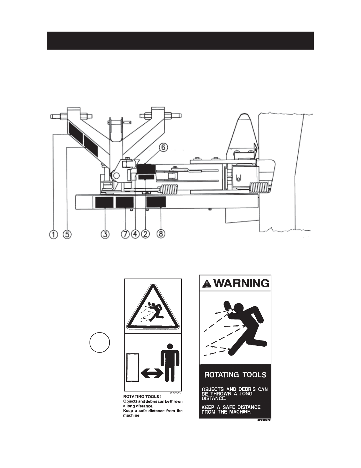
2. Stay a safe distance away from the mower when discs are rotating.
3. For safe machine operation, it is imperative that cutting tools be fitted in accordance with the manufacturer’s
recommendations. Use only the tool outfit supplied with the machine.
4. Eachtimebeforeusingthemower,inspectconditionofcuttingelements(knives,discs).Replaceanymissing,
wornordamagedcutting elements immediately. Use onlygenuineKUHNspareparts.
5. Toavoidcreatingdangerousoutofbalanceforces,alwaysreplacemissing,damagedorwornknivesinpairs.
6. When replacing knives or discs, systematically inspect their securing elements as per the manufacturer’s
recommendations.
7. Regularly inspect the disc mower’s protection cover. Worn or damaged protection covers must be replaced
immediately.
8. Protectiondevices(suchasguards,shieldsetc.)areintendedtopreventstones,rocksorotherforeignobjects
frombeingprojected.Theyalsopreventaccesstothemachine’sdangerzones.Therefore,itisimperativethat
protectiondevicesare put in placeandproperly secured each timebeforeusing the machine.
9. Crushingandshearingzoneswhichcouldcauseseriousbodilyinjurywhenchangingthemachinefromtransport
towork positionandviceversamayexist. Topreventpossibleinjury,beextra carefulwhenmaneuveringand
ensure that everyone is at a safe distance away from the machine.
10.PTOdrivetothemowermustneverbeengagedunlessthecutterbarskidshoesareincontactwiththeground
andtheprotectivecoverisfoldeddown.
11.Groundof thepastures to bemown must befree of foreignobjects.
12.Even when the machine is used in accordance with its purpose, objects may be projected. It is therefore
imperativethateveryonebekeptawayfromthedangerzone,thatextracarebetakenandthatextra precaution
(suchassafetyindicators)betakenwhenmowingpasturesalongsideroadsornearpublicareas(parks,schools
etc.).
13.Nevermowinreverse.
14.WhendisengagingthePTOdrive,movingpartscontinuetorotateforsometime.Waitforallmovingpartstocome
toacompletestopbefore approaching the machine.
15.Ifanobstructionishit,stopthetractorimmediately,disengagePTOdrive,turnoffengine,removeignitionkey
and wait for all moving parts to come to a complete stop.
Checktheentiremachineforanydamagebeforeresumingwork.
16.Itisstronglyrecommendedtohaveyourmachinecheckedbyyourdealeraftereachseason,especiallyblades
and discs and their fixing devices (nuts, bolts etc.).

- 8 -
SAFETY DECALS
THEFOLLOWINGSAFETYPICTORIALSHAVE BEEN PLACED ON YOUR MACHINE IN THE AREAS
INDICATED.THEYAREINTENDEDFORYOURPERSONALSAFETYANDFORTHESAFETYOFTHE
PEOPLE WORKING WITH YOU. THE TEXT SHOWN ON THEM GIVES THEIR PRECISE MEANING.
KEEP THE PICTORIALS LEGIBLE. IF THEY ARE NOT, REPLACE THEM.
1

- 9 -
2
3
4
56

- 10 -
8
7

- 11 -
Numberof discs 6 7 8
Width of cut 2.40 m / 7' 10" 2.80 m / 9' 2" 3.10 m / 10' 2"
PTOpowerrequirement 31 kW (42 hp) 37 kW (50 hp) 41 kW (56 hp)
P.TO.speed(rotationalfrequency) 540rpm(min-1)540rpm(min-1)540rpm(min-1)
Discspeed(rotationalfrequency) 2986rpm(min-1)2986rpm(min-1)2986rpm(min-1)
Width in transport position *0.17 m(7") widerthan tractorwidth
Lift system **hydraulic **hydraulic **hydraulic
Weight(approx.):
- GMD 600 GII / 700 GII / 800 GII 535 kg / 1177 lbs 567 kg / 1247 lbs 646 kg / 1421 lbs
- GMD 600 GII-HD/700 GII-HD/800 GII-HD 548 kg / 1206 lbs 582 kg / 1280 lbs 663 kg / 1459 lbs
Bevelgearboxoilcapacity 0.45 l / 1 US pint
Oil quality : SAE 80 W EP (GL4) 0.75Imppint
Cutterbaroilcapacity 2.00 l / 4.25 US pint 2.25 l / 4.75 US pint
Oil quality : SAE 80 W EP (GL4) 3.5 Imp pint 4 Imp pint
* Applicable if machine is attached in such a way that a 5 cm / 2" distance "A" is respected (see page 18).
** On tractor sideasingle acting outlet(preferablywith free floating position)isrequired.
ASSEMBLY
Tofacilitateshippingofthediscmowers,certainpartsorassembliesarepartiallydisassembledtoreducebulk.To
assemble these parts proceed as follows :
TYPE GMD 600 GII GMD 700 GII GMD 800 GII
GMD 600 GII-HD GMD 700 GII-HD GMD 800 GII-HD
TECHNICAL SPECIFICATIONS
1. Fitting the break-away latch
Fit break-away latch (P) on headstock yoke (Q) and
mainframeyoke(R)with2pins(S)and 4rollpins(T)
(dia. 6 x 36) as shown in photo 1.
*0.21m(8") wider
thantractor width
1

- 12 -
2. Mounting chassis to cutterbar
Makesurethattheboreofnylonbushingsiscleanandwellgreased.Removeprotectivepaintfromthefrontcover
ofbevelgearboxwherebushingsmakecontact.
Attach the frame to the cutterbar using 2 self locking screws (B) (M 16 x 50) and 2 washers (A) (diameter 16,5 x
60) as shown in photo 2 and fig.2. Torque : 30 daNm / 220 ft.lbs.
Install the compensating spring rod (N) to the pin (C) using roll pin (E) (diameter 8 x 50) (photo 2).
3. Assembly of belt shield and belts
- Installtheinnerbeltshield(D)(photo3)inplaceand
securewiththe3spacerbolts(E)tapedonthestop
chain. Torque to 5 daNm / 40 ft.lbs.
- Installclosingplate(F)equippedwithelasticnut as
shown in photo 3.
On GMD 800 GII / 800 GII-HD, mount the inner
closing plate (M) using an elastic nut and a self-
locking screw (N) (M 8 x 12) (photo 3A).
- InstalltheV-belts(G)ontothepulleys(photos3and
3A).
- Place tensioning spring (K) inside spacer tube (J)
andinstallbothpartsoverguide (L) (fig. 3).
- Slidespecialwasher(R)ontobolt(H)andinstallthis
bolt into guide (L) as shown in figure 3 and photo 3
A.
2
Fig. 2
3
3A
Fig. 3

- 13 -
- Tensionthe V-belts (G)(photo 3) bytightening the
bolt(H) with the18mmboxspanner (O), delivered
with the machine (photo 3 A).
- For the correct V-belt tension, tighten the bolt (H)
until the spacer tube (J) is in contact with the main
frameplate(E)andthewasher(R),thentightenthe
bolt with 2 additional complete turns.
Note : The 2 turns of the bolt necessary to obtain a
correcttension,onlyapplytonewsetsofbelts
to compensate for the initial stretch new belts
aresubjecttoduringthefirstcoupleofhoursof
use.
- Attachouterbeltshield(X)with3washersand3cap
nuts (I) (photo 4). Torque : 5 daNm / 40 ft.lbs
- Assemble closing plate and outer belt shield with
one self-locking screw (K) (M 8 x 16) (photo 4).
OnGMD800GII / 800GII-HD,assembletheinner
closingplateandtheouterbeltshieldwithoneself-
locking screw (K) (M 8 x 12) (photo 4A).
4. Installing the frame pipe
-Aftercleaningattachframepipe(L)(photo5)tobevel
gearboxwith4screws(M)(M16x40).(Torque:21
daNm / 155 ft.lbs).
3B
4
4A
5

- 14 -
5° Installing pivoting lever, lift rod, connecting plate, cord and hydraulic hose
- Installpivotinglever(A)onpin(B)andsecurewitha
roll pin (dia 6 x 36) (photo 6)
- Installliftrod(N)(photo6)onpin(0)andsecurewith
a roll pin (dia 6 x 36).
- Connectlift rod (N)andthe cylinder rodconnecting
plate( C)tothe pivotinglever(A)withpin(Q)and2
roll pins (dia 6 x 30) as shown in photo 6.
- Thread cord (D) through the eyelet (E), then attach
themetallichook (X) to stopplate(G)andclosethe
hook'seyeletwithapairofpliers.Thiscordisfactory
installed on transport latch (F) (photo 6 A).
- Threadcord(D')througheyelet(E')andthroughthe
eyelet of transport latch (F) which already houses
cord(D).Thentieaknot(Y)tothelooseendofcord
(D')(photo6A).
- Fix hose (Z) to cylinder using a hollow screw and a
copperwasheroneachsideofthebanjojoint(photo
6 A).
6° Compensating spring, inner shoe and inner swath board assembly
- Connectcompensatingspring(P)(photo7) to axle
(R) of frame pipe and secure with 2 roll pins(dia.
8 x 40).
Thisoperationiscarriedouteasilybyattachingthe
machine to a tractor and raising the cutterbar until
the spring mounting hole lines up with pin (R).
- Fitinnershoe(I)bymeansof4cupsquarebolts(J)
(M10x25)and4selflockingnuts(M10)(photo8).
Ifitbecomesnecessarytotransportthe
machineonatrailerafterassembly,the
compensating spring should not be
connected at this stage, thus allowing
theframetorestsecurelyonitsleftskid.
66A
78

- 15 -
- Fixtheinnerdeflectorshield(S)(photo8A)using3
cup square bolts (T) (M 10 x 20), 3 plain washers
(diameter11x24x2)and3selflockingnuts(M10).
To assemble the shield (S) easily, install all of the
bolts(T) into placebeforetighteningthem.
Theangularpositionoftheswathwheelcomparedtothecutterbarcanbeadaptedtoworkingconditions
enablingaregularflow of the cut croptowardstherear.
Position the swath wheel so that maximum angle (A') (fig. 9 A) is obtained. In difficult working
conditions (long, dense, bent over crops) position it towards minimum angle (A) (fig. 9 A).
7. Installing outer disc with cone and outer swath wheel
- Attach the outer disc with cone using 4 hexagon
screws(M12x20),4springwashers(conicalcentre
parttowardsthetop)and,ifnecessary,ashimplate
(code568 071 00)(see page 29,fig. 2), so thatits
largest diameter is positioned at a right angle in
relationtotheadjacentdisc(seepictorialopposite).
Tighten to 12 daNm (90 ft.lbs).
- Attachswathwheelassembly(U)toouterskidshoe
(photo 9) with 2 cup square bolts (V) (M 12 x 35), 2
conicalwashers(dia.13mm)and2self-lockingnuts
(M12).
Torque: 8.5daNm/65ft.lbs
Beforetighteningscrews(V),makesurethatswath
wheeldoesnotcomeintocontactwithconecoveror
knives.
Keep to a distance of X = 15 to 25 mm / 5/8" - 1".
8A
9A
9

- 16 -
8. Safety guard and locking device assembly
- Attachthefrontsafetybar(B)toits3hinges(C)with
the5cupsquarebolts(P)(M10x25),5self-locking
nuts (O) (M 10) and 5 flat washers (Q) (Ø 11 x 24
x 2) (fig. 10).
- Thenattachthepre-assembledfrontsafetybar(B)
at(N)with3hexagonalscrews(M12x75)andself-
lockingnuts(M12)(photo11).Donottightenthese
3screwscompletely,sothatthefrontsafetybarcan
still pivot.
- Next attach rear safety bar (A) with 5 round head
bolts (P) (M 10 x 25) and 5self-lockingnuts (O)
(M 10) (fig. 10 and photo 11). Fit end-plug (Z) on
rear safety bar (A) (photo 11).
10
11
12 12A

- 17 -
1. Minimum tractor power used should be 31 kW
(42PTOhp)fortheGMD600GII /600GII-HD,37
kW(50PTOhp)fortheGMD700GII /700GII-HD
and42kW(57PTOhp)fortheGMD800GII /800
GII-HD.Iftractorpowerisnotsufficient,qualityof
work will not be satisfactory.
2. GMD600GII /600GII-HD,GMD700GII /700GII-
HDandGMD800GII /800GII-HDdiscmowerscan
be adapted to all tractors having a PTO speed
(rotational frequency) of 540 rpm (min-1)and
equippedwithanormalizedCat.2threepointhitch.
3. GMD600GII /600GII-HD,GMD700GII /700GII-
HDandGMD800GII /800GII-HDareequippedwith
adjustablelowerhitchpinsallowingthemachineto
beoffset50mm(2")totheleftand50mm(2")tothe
right.
4. Toadjustlowerhitchpins(A)(photo13),loosenthe
4hexagonalscrews(H)ofcollarflanges(V)oneach
side.Repositionlowerhitchpinsrespectingdimen-
sion825mm(2’8")(page18)andretightenscrews
(H). Torque : 12 daNm/88 ft.lbs.
GENERAL INFORMATION
- Installcover(D)asshowninphoto12.BucklestrapsaroundthepipeframeatE.Bucklestraps(F)aroundfront
and rear safety bar. All these straps are attached to the underneath of the safety cover.
- Punch3holesinthesafetycoverat(G)anduse3cupsquarebolts(R)(M10x35)withself-lockingnuts(0)(M
10)(fig9)andplainwashers(Q)(dia.11x24x2)toattachthefollowingcomponentsontheoutsidearmsofthe
safetybars:safetyguardlockingdevice(S);safetycover(D);stoprod(J)(seefig.10andalsorefertophotos
11, 12 and 12 A).
- Fixthe rubber stopper (W) ontothe canvas frameusing a nut (M8) (photo12).
Note : Make sure that the pivot axis of the safety guard locking device (S) is lined up with the pivot axis
(N) of the front safety bar before tightening self-locking nuts (O).
CAUTION : ALWAYS OPERATE MOWER WITH SAFETY COVER IN PLACE AND THE
FRONT END OF THE COVER LOWERED. NEVER LEAN AGAINST OR STAND ON
SAFETYCOVER.
The18mmboxspanner(T)deliveredwiththemachine
has to be stored in holder (U) (photo 14).
This box spanner is used to make the following
operations:
-Unlockingthe safety guard
-Tensioning the belts
-Tensioningthecompensatingspring
-Replacingknives
- Dismounting discs.
- Checkthetorqueofthescrews(H)afterthefirst
ten hours of work following the modification of
the hitch pins’ position.
13
14

- 18 -
ADAPTING TO TRACTOR
Attachment of lower links and
positionning of hitch pins :
Followfig.1forcategory2tractorswithnarrowwheel
track.
Follow fig. 2 for category 2 tractors with standard
wheeltrack.
Follow fig. 3 for category 2 tractors with wide wheel
track.
NOTE : -Usetheaboveapproximatedimensionsfrom
centre of tractor to outside of wheel to
determineifthetractorwheeltrackisnarrow,
standardorwide.
-Always attach machine in such a way
that distance (A) is approximately 50
mm (2").
Follow fig. 4for Cat. 2 tractors with very wide
wheeltrack.Inthiscasealengthenedlefthitch
pinforupto200mm(8")offsetisrequired(see
optionalaccessoriesonpage38).
CAT 2
FIG. 4
CAT 2
FIG. 3
CAT 2
FIG. 2
CAT 2
FIG. 1
This manual suits for next models
5
Table of contents
Other KUHN Farm Equipment manuals
Popular Farm Equipment manuals by other brands

Schaffert
Schaffert Rebounder Mounting instructions

Stocks AG
Stocks AG Fan Jet Pro Plus 65 Original Operating Manual and parts list

Cumberland
Cumberland Integra Feed-Link Installation and operation manual

BROWN
BROWN BDHP-1250 Owner's/operator's manual

Molon
Molon BCS operating instructions

Vaderstad
Vaderstad Rapid Series instructions