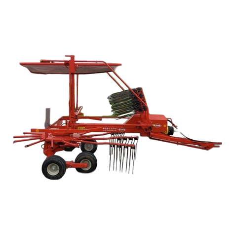
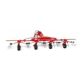
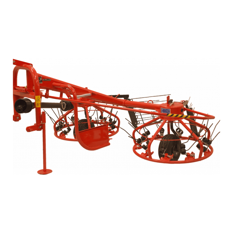
KUHN GF 5001 MH User manual

ASSEMBLY / OPERATOR'S MANUAL
GF 5001 MH - GYROTEDDER
N° 95204 C.GB - 06.2004

DEAR OWNER,
In buying a KUHN machine you have chosen wisely. Into it have gone years of thought,
researchandimprovements.Youwillfind,ashavethousandsofownersallovertheworld,that
you have the best that engineering skill and actual field testing can produce. You have
purchased a dependable machine, but only by proper care and operation can you expect to
receive the performance and long service built into it.
This manual contains all the necessary information for you to receive full efficiency from your
machine.Theperformanceyougetfromthismachineislargelydependantuponhowwellyou
readandunderstandthismanualandapplythisknowledge.PleaseDONOTASSUMETHAT
YOU KNOW HOW TO OPERATE AND MAINTAIN YOUR MACHINE before reading this
manual carefully. KEEP THIS MANUAL AVAILABLE FOR REFERENCE.
YourKUHN dealerwillinstruct youonthegeneral operationofyourmachine. He isinterested
that you get the best performance possible and will be glad to answer any special questions
that may arise regarding the operation of the KUHN machine.
Your KUHN dealer can offer a complete line of genuine KUHN service parts.
These parts are manufactured and carefully inspected in the same factory that builds the
machine to assure high quality and accurate fitting of any necessary replacements.
When ordering service parts it is important that you indicate the type of machine concerned
and its serial number.
Forthisreasonpleasecompletethemodelidentificationplatediagrambelowwiththerequired
information. This will provide you with an easy reference for future service parts orders.
ABOUT IMPROVEMENTS
KUHN iscontinuallystriving to improveitsproducts and,therefore,reserves the righttomake
improvements or changes when it becomes practical to do so, without incurring any
obligations to make changes or additions to the equipment sold previously.

- 1 -
CONTENTS
Page
Safety 2
Safetydecals 9
Technicalspecifications 11
Assembly instructions 12
Attachment : - to the tractor 17
-PTOshaft 18
Workingpositionandadjustments 19
Operatingspeed 21
Transportposition 22
Parkingthemachine 23
Lubrication 24
Optionalequipment 25
Conditionsof limited warranty 29
Copyright 2003 KUHN S.A.

- 2 -
SAFETY ADVICE
Theabovesymbolisusedthroughoutthismanualeverytimerecommendationsaremadeconcerningyoursafety,
the safety of others, or the good operation of the machine.
These recommendations must be made known to all machine operators.
DESIGNATED USE OF THE MACHINE
TheGF5001MHGyroteddermustonlybeusedfortheworkforwhichithasbeendesigned:spreadingandturning
strawandpre-mowedfodder.Whenfittedwithareductiongearbox,themachinecanalsobeusedforformingsmall
night swath in order to reduce the amount of humidity getting into the crop over night.
Themanufacturerisnotheldliableforanydamageresultingfrommachineapplicationsotherthanthosespecified
bythemanufacturer.
Any use other than the designated operation is at the risk and responsibility of the operator.
Designated use of the machine also means :
- following operation, maintenance and repair recommendations given by the manufacturer ;
- using only genuine spare parts, equipment and accessories as designated by the manufacturer.
The GF 5001 MH Gyrotedder must only be operated, maintained and repaired by competent persons who are
familiar with machine specifications and operation and are aware of any danger involved.
The operator must imperatively respect current legislation concerning :
- accident prevention,
-work safety,
-publictrafficcirculation.
All safety advice indicated on the machine must be strictly observed.
The manufacturer is not held liable for any damage resulting from machine modifications carried out by the
operatorhimself or byathird party withoutpreviouswritten agreement fromthe manufacturer.

- 3 -
GENERAL SAFETY RECOMMENDATIONS
Before operating the machine, always ensure that tractor and machine are in accordance with work safety and
road traffic regulations.
BASICPRINCIPLES
1. Inadditiontotherecomendationsgiveninthismanual,legislationonworksafetyandaccidentpreventionmust
also be respected.
2. Advice is indicated on the machine, specifying safety recommendations in order to prevent accidents.
3. When travelling on public roads, the operator must respect all road traffic regulations.
4. Before starting work, the operator must be familiar with all machine controls, handling devices and their
functions. Once at work, it is too late to do so!
5. Useatractorequippedwithasafetycab.Keepwindowsandroofhatchclosedforreducedsoundlevelwhile
operatingthePTOdriveimplement.
6. Beforestartingupthemachineandbeginningwork,checkthesurroundingarea(bewareofchildren!).Make
sure there is sufficient visibility.
Keep all people and animals away from the danger zone of the machine (risk of projection!).
7. Carrying people or animals on the machine when working or in transport is strictly forbidden.
8. Machine must only be attached to tractor using means provided and in accordance with current safety
standards.
9. When attaching or removing the machine, place the parking stand into the corresponding position.
10. Special care should be taken when attaching or removing the machine from the tractor.
11. Before attaching the machine, ensure that the front tractor axle is sufficiently ballasted.
Ballast is to be placed on the supports provided in accordance with instructions of the tractor manufacturer.
12. Do not surpass the maximum axle load or the overall transport weight as prescribed by the manufacturer.
13. Do not exceed the maximum transport width authorized by road traffic regulations.
14. Beforetransportingthemachineonpublicroads,ensurethatalllegallyrequiredguardsandindicators(lights,
reflectors ...) are in place and in good operation.
15. Alloperatingcontrols(cords,cables,rods...)mustbepositionedsothattheycannotbesetoffaccidently,risking
accident or damage.
16. Before traveling on public roads, put the machine into its transport position as instructed in this operator’s
manual.

- 4 -
17. Neverleave the tractor seatwhile the machineis operating.
18. Drive speed must be adapted to ground conditions as well as to roads and paths.
Always avoid abrupt changes of direction.
19. Precision steering, tractor adherence, road holding and efficient braking are influenced by the type of
implement,weight, ballast of frontaxle, ground or roadconditions. It is thereforeof utmost importancetobe
cautious in every given situation.
20. Beparticularlycautiouswhenturningcorners,payingattentiontomachineoverhang,length,heightandweight.
21. Keep clear of the machine operating area.
22. WARNING ! Danger of crushing and shearing can exist when components are operated by hydraulic or
pneumaticcontrols.
23. Beforeleavingthetractororbeforeadjusting,maintainingorrepairingthemachine,turnofftheengine,remove
the ignition key and wait until all moving parts have come to a complete stop.
24. Donotstandbetweenthetractorandthemachineunlessthehandbrakeistightand/orstopshavebeenplaced
underthewheels.
25. Beforeany adjustments, maintenanceorrepairs are carried out,ensurethatthe machine cannot bestarted
up accidentally.
PRECAUTIONS TO BE TAKEN BEFORE OPERATING THE MACHINE
1. Do not wear loose clothing which could be caught up in moving parts.
2. Wear the individual protection equipment corresponding to the work which is planned (gloves, shoes, eye
protection, helmet, ear protectors...).
3. All operating controls (cords, cables, rods ...) must be positioned so that they cannot be set off accidentally,
causing accident or damage.
4. Beforeoperatingthemachine, checkthetightnessofallnutsand bolts,particularlyonrotatingparts(blades,
tines, knives, spades ...)
5. Beforeoperatingthemachine, ensurethatall safety guards are firmly in placeandingoodcondition.Ifworn
or damaged, replace immediately.
ATTACHMENT
1. Whenattachingorremovingthemachinefromthetractor,positionhydraulicliftcontrolleverinsuchawaythat
it cannot be set off accidentally.
2. When attaching the machine to the tractor 3-point linkage, ensure that diameter of the link pins corresponds
to the diameter of the ball joints.
3. WARNING ! Danger of crushing and shearing can exist in the lifting zone of the 3-point linkage !
4. Donotstandbetweenthetractorandthemachinewhenoperatingtheoutercontrolleveroftheliftmechanism.
5. Intransport,themachineliftmechanismshouldbestabilizedbytractortierodstoavoidfloatationandsideshifting.
6. When transporting the machine in the raised position, lock the lift control lever in place.


- 5 -
POWER TAKE-OFF
1. Use only the PTO shaft supplied with the machine or recommended by the manufacturer.
2. PTO guards must always be in place and in good condition.
3. Check for correct PTO overlap when at work and in transport.
4. Before attaching or removing the PTO shaft, disengage PTO shaft, turn off engine and remove ignition key.
5. IfaprimaryPTOshaftisequippedwithaslipclutchorafreewheel,thesemustbefittedonthemachinePTO.
6. Ensure that PTO shaft is always correctly fitted and locked into place.
7. Make sure guards are correctly in place and secured with the safety chains provided.
8. BeforeengagingPTO,ensurethatPTOspeed(rotationalfrequency)anddirectionofrotationareinaccordance
withmanufacturer'srecommendations.
9. Before engaging PTO, keep all people and animals clear from the machine.
10. Never engage PTO shaft when tractor motor is turned off.
11. Neversurpass the PTO angle recommendedbythemanufacturer.
12. WARNING! Rotating elements cancontinue turning momentarilyafter PTO isdisengaged. Keep clear until
allrotatingelementsareatastandstill.
13. When removing the machine, place PTO shaft on the supports provided.
14. Fit the safety cap on tractor PTO.
15. Replaceany wornordamaged PTO guards immediately.
Rotationspeed...rpm(AmericanMeasure)isalsoexpressedinmetricmeasure:Rotationalfrequency...min-1.Both
unitsareequivalent,for example : Rotation speed540rpmequalsRotationalfrequency540min-1.

- 6 -
HYDRAULICSYSTEM
1.Beware ! Thehydraulic circuit isunder pressure (maximumworking pressure :200 bars/2900 psi).
2. When fitting hydraulic motors or cylinders, ensure that connections have been made correctly, as per
manufacturer’sinstructions.
3. Before connecting hoses to the tractor hydraulics, ensure that tractor and machine circuits are not under
pressure.
4. Itisstronglyrecommendedthattheoperatormarksthehydraulicconnectionsbetweentractorandmachineto
avoidmakingawrongconnection.WARNING!Functionscouldbereversed(forexample:lift/lower).
5. Regularlycheckthehydraulichoses!Replacethehydraulichosesevery5years.Damagedorwornhoses must
immediatelybe replaced .
Whenreplacingthehydraulichoses,makesuretousehoseswiththespecificationsandqualityrecommended
bythemanufacturerof the machine.
6. Should a leak be found, take all necessary precautions to avoid accidents.
7. Any liquid under pressure (particularly oil from hydraulics) can penetrate the skin and cause severe injury. If
injured,see a doctor immediately,therecould be dangerofinfection.
8. Beforeanyadjustments,maintenanceorrepairsarecarriedout,lowerthemachine,depressurizethecircuit,turn
offtheengineandremoveignitionkey.
TIRES
1. Beforeany adjustments,maintenance or repairs arecarried out, ensure thatthe machine rests onthe ground
and is perfectly stable so that it cannot move accidentally (put wedges in place).
2. Assembly,disassemblyandrepairofwheelsandtiresmustonlybecarriedoutbycompetentpersonswhoare
equippedwithstandardizedtools.
3. Checktirepressureregularly!
Respectmanufacturer’srecommendationsontirepressure.

- 7 -
MAINTENANCE
1. Before checking for any machine malfunction and before adjusting, maintaining or repairing the machine,
disengage PTO, turn off engine and remove ignition key.
2. Check tightness of nuts and bolts regularly. Retighten if necessary.
3. If the machine is raised, prop it up in a stable position before carrying out any maintenance work.
4. When replacing a working part, wear protection gloves and only use standardized tools.
5. Itisforbiddentodiscardanyoil,greaseorfilters.Thesemustbegiventowastedisposalorganizationstoprotect
theenvironment.
6. Disconnect power source before any work is done to the electric system.
7. Check safety guards regularly, particularly those that are subject to wear. Replace immediately if damaged.
8. Spare parts used must be in accordance with specifications and standards as defined by the manufacturer.
Use only genuine KUHN parts !
9. Before any electric welding is carried out on tractor or attached machine, disconnect generator and battery
terminals.
10. Repairs on elements under pressure or tension (springs, accumulators etc...) must only be carried out by
competentpersonswithstandardizedequipment.

- 8 -
SPECIALSAFETYRECOMMENDATIONS
When changing the machine over from the work to the transport position or vice versa, danger of crushing and
shearing can exist.
Be especially careful and keep all persons away from vicinity of the machine when maneuvering.

- 9 -
SAFETY DECALS
THEFOLLOWINGSAFETYPICTORIALSHAVEBEENPLACEDON YOUR MACHINE IN THE AREAS
INDICATED.THEYAREINTENDEDFORYOURPERSONALSAFETYANDFORTHESAFETYOFTHE
PEOPLE WORKING WITH YOU. THE TEXT SHOWN ON THEM GIVES THEIR PRECISE MEANING.
ENSURETHATTHESEPICTORIALS ARE ALWAYS LEGIBLE.IFTHEYARENOT, REPLACE THEM.

- 10 -
2
3
1
4

- 11 -
6
TECHNICAL SPECIFICATIONS
Number of rotors 4
Working width (Din. 11220) 5.00 m / 16' 7"
Width in working position 5.43 m / 17' 9"
Transportwidth 2.84 m / 9' 2"
Length in transport position 2.31 m / 7' 7"
Length in working position 2.31 m / 7' 7"
Power requirement 15 kW / 20 hp
Weight with PTO 522 kg / 1148 lbs
Tyres 15 x 6.00 - 6
Tyre pressure 2 bars / 29 psi

- 12 -
ASSEMBLY INSTRUCTIONS
2) Fitting the connecting frame (photos 2,
2A and 2B)
Assembleconnectingframe(P)tocrossbar(T)usingthe
followinghardware:
- 4bolts(D)(M12x100) and self-locking nut M12
- 1bolt(D’)(M12x110),plainwasher(12.5x25x1.5)and
self-lockingnutM12.
Alsoassembletheconnectingframe(P)tocentralgearbox
(J)using6 self-locking screws (K) (M12x35)(photo2A).
Tighten all this hardware to 10 daNm / 75ft.lbs
Note : Make sure to place hydraulic hose holder (L)
betweentheconnectingframeundersideandthe
self-lockingnutM12whenfittingbolt(D’)(photo2).
Connecthoses(RandS)tothehydraulicT-union(U)and
to hydraulic cylinders (V) as shown on photos 2, 2A and
2B.
2B2A
2
1
1) Fitting of the outer wings and cylinders
(photo 1)
Make sure not to invert left and right wings. Grease
Digidrivecouplingfingers.
Connectcylinderbarrels(V)toaxles(A)usingrollpins(C)
(8x40)andplainwashers(B)(21x33x4).Inserthinges(M)
in housings (N) respecting the rotor timing thanks to O-
rings(Q)placedontheDigidrivecouplingfingers.
Installpivots(E)usingrollpins(F)(8x50and5x50).Make
suretofitpivotsequippedwithanangledgreasezerkatthe
rearofthemachine.
Inserttheflexibleguardstrips(G)underneathbrackets(H).

- 13 -
5) Fitting the wheels (photo 4)
Fitthepre-assembledwheels(G)intotheirholders(F).
Placeashimwasher(I)(dia.35x45x2.5)ontopofthe
holder.Theninstallshimwasher(K)(dia.35x50x1).
Secureinplacewithretainingring(H).Tocompletethe
jobinstallprotective caps (J).
4
3A
3
3) Fitting the 3-point frame (fig. 3)
Attachthe3-point frame(C) to the connectingframe
(P) bymeansoftheverticalpivot pin (A)andsecure
in place with roll pins (E) (5 x 50 mm) and (E’)
(8 x 50 mm) as shown in figure 3.
Attach the pendulum arm(B)tothe3-pointframe(C)
by means of the horizontal pivot pin (F).Secure the
horizontal pin (F) with roll pins (G) (8 x 50 mm). The
roller(H ) mustlocate in housing(I).
Slide cover (Y) in place on triangular plate (I) of
connectingframe(P)with2hexagonalscrews(M10x25)
and2 self-locking(M10)(drawing3and photo3A).
4) Fitting the stand (photo 3A)
Slideparkingstand(M)inhousing(N)andfitrollpin (X)
(dia. 8 x 55). Lock the parking stand in the lowered
position with R-clip (O) and install PVC cord (Q) as
shown in photo 3A.

- 14 -
8) Fitting tine arms and tines
Before fitting tine arms and tines fold the intermediate and the outer rotors in working
position.
Fit the tine arms (B) as shown in figure 7.
1 = self-locking screw M 12 x 30 2 = self-locking nut M 12 (tighten to a torque of 12 daNm (88 ft.lbs).
Fitthe tines (F) on thetine arms (B)in such a way thatthe pressure fromthe tines closesthe spiral(the tines are
facing in the direction of rotation of the rotors) (fig. 8).
Position the deflectors (D). Fit the screws (A), position washers (C), then tighten the self-locking nuts (E)
(fig. 8) to a torque of 16 daNm (120 ft.lbs).
During the first few hours of work, make frequent checks of tine nut and bolt tightness. If
necessary, retighten to 16 daNm (120 ft.lbs) to avoid the possibility of loss or breakage.
6)Fittingreflectors(fig.5)
Attachreflectorsupport(1)tocentraltubing(2)oneach
sideofthemachinebymeansof1hexagonscrew (3)
(M 12 x 40), 1 self-locking screw (5) (M 12 x 40) and
1 spacer (7), as shown in fig. 5.
Nextstickredreflectors(8)andwhite reflectors (9) to
theendof supports (1).
7) Fitting rear shield (photo 6)
Attachrear shield (T) toreflector supports (1) using4
hexagon screws (V) (M 8 x 20), 4 plain washers
(diameter 9 x 18 x 1,5) and 4 self-locking nuts (M 8).
Also attach to connecting frame (P) using 1 hexagon
screw (W) (M 8 x 12) and 1 lock washer (M 8).
6
5

- 15 -
9) Fitting control cords (photo 9)
Cut one of the cords (D 1) to 1,7 m (5' 7"). Thread it through plate (P) as shown in drawing below.
Threadeachendofthecordthroughlockarm(V)andtieaknotateachend.Inserttheothercord(D2)throughthe
upper hole of support plate (C) then through plate (P) and tie a knot.
Thread the other end of cord through handle (A) and tie a knot at desired length so that locks can easily be
maneuvered from the tractor seat. Cut off surplus cord at the knot and fit plug into handle (A).
To avoid that cords are too lax above the machine, tie a knot (N) in the cord just before support plate (C).
Theninstallhydrauliccouplerholder(H)oncover(S)(photo9).

- 16 -
10) Fitting the safety guards (photos 10 and 10 A)
Thesafetyguardsareprovidedwiththemachinetogiveimprovedprotectionagainstpossibleaccidentsandtherefore
ensuremaximumsafety.
Fitboth guards (6) ontosupport(7) and secure themwith4 hexagon bolts(8)(M 10 x 50)andnuts (M 10) (photo
10). Torque to 5 daNm / 37 ft.lbs.
Sideguards(5)arefittedtooutsidehousings(11)using2hexagonalbolts (1)(M12x60)and2serratedwashers
(M 12) (photo 10 A).
Tighten hexagon bolts to 9 daNm / 65 ft.lbs.
Install plugs (3) and (4) on the safety guards (5 and 6).
10A10

- 17 -
ATTACHMENT
FITTING TO THE TRACTOR
TheGF 5001 MH canbefittedto all tractors equipped with a DIN orASEAStandard3-pointlinkage.The lower
linkpinsare22mmand 28mmdiameterfortractorswithCat.IandIIlinkage.Thelowerlinkpinsshouldbeattached
to the tractor link arms (P) inside the 3-point frame for Cat. I tractors and on the outside for Cat. II tractors. In the
latter case, use the 25 mm diameter link pins to attach tractor top link (Q) to the pendulum arm (A) (photo 11).
Attachmentshould be undertakenwiththe pendulum arm(A) unlocked (leverVin the lowerposition, photo 12).
The pendulum arm has three attachment positions to suit varying tractor top link lengths.
Connect hydraulic hose (R) to a female hydraulic connection at the rear of the tractor (photo 11).
Whenthemachineisattachedtothetractor,raisestand(D)andsecurewithspringcotter(O)(photos11and12).
Whenconnectinghydraulichose(E)totractor,ensurehoseisplacedabovecentralguard(S)
(photos11and 12).
11 12

- 18 -
PTO SHAFT
ConnectthePTOshafttothe540rpm(min-1)tractordrive(withthesafetyclutchfittedonthemachineside)(photo
11).
Make sure PTO length is correct :
1) WhenthePTOisinitsmaximumextendedposition,aminimumtubeoverlapof300mm(12")mustbemaintained.
2) WhenthePTOisinitsmaximumoverlapposition(retracted),tubesshouldnotbuttagainsttheyokes.Asasafety
measure a clearance of at least 2 cm (0.8") must be maintained. If this is not the case, shorten the two
transmissiontubesandthetwoguardtubesbythesamelength(fig.13and14).Bevelandcleanthetubes(fig.
15)and grease the inside ofthe outer tube (fig. 16).
3) NeveroperatethePTOattoogreatanangle(30°maximum).
Theserecommendationsandadjustmentsmustberespectedtoavoiddamageorprematurewearof
thePTO.
Never connect the PTO to the 1000 rpm (min-1)tractor drive.
To avoid accidents which could be serious, make sure that the guards are always correctly
inplaceandsecuredwiththesafetychains(photo11).Onmachinesidethesafetychainmust
be attached to the frame (photo 24, page 23). Worn or damaged guards must be replaced
immediately.
Table of contents
Other KUHN Farm Equipment manuals
Popular Farm Equipment manuals by other brands

Meec
Meec 721-331 User instructions

Standen
Standen T2 Operator's handbook

Grouser Products
Grouser Products 770HD Steiger T4B Wheeled Owner's manual & parts book

Omarv
Omarv Torino 160 Use and maintenance manual

360 YIELD CENTER
360 YIELD CENTER 360 SOILSCAN Setup instructions

Gaspardo
Gaspardo DP SPRINT GIGANTE Use and maintenance