EL92-180/205/230
62. - Contents
KN007CGB_F
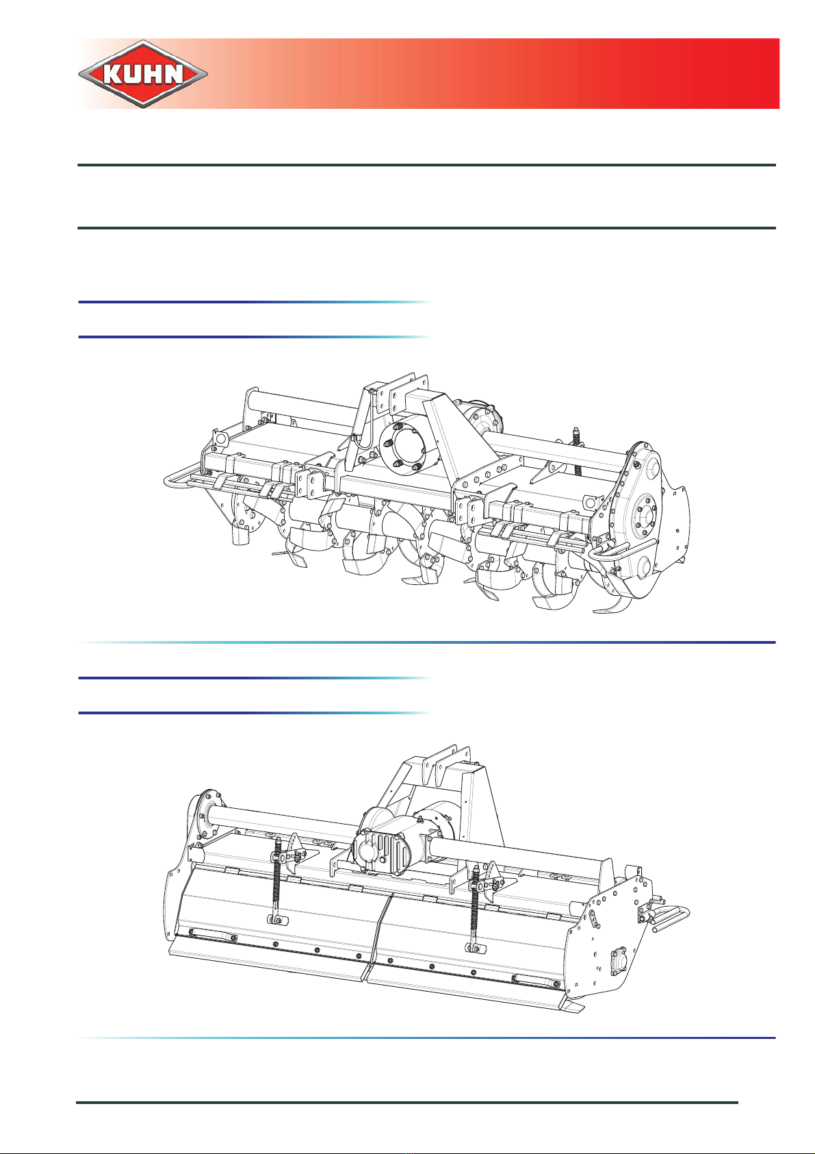
Power tiller
9. Optional equipment......................................................................................................58
9.1 32x38-8 spline yoke....................................................................................................................... 58
9.2 Side discs ......................................................................................................................................58
9.2.1 Working depth adjustment................................................................................................ 58
9.3 Track eradicators with flexible tines...............................................................................................59
9.3.1 Fitting................................................................................................................................ 59
9.3.2 Coupling and uncoupling.................................................................................................. 60
9.3.3 Adjustments in working position .......................................................................................61
9.3.4 Maintenance..................................................................................................................... 62
9.4 Set of gearwheels.......................................................................................................................... 62
9.4.1 Rotor speed adjustment ................................................................................................... 62
9.5 Lighting and signalling ...................................................................................................................64
9.5.1 Coupling and uncoupling.................................................................................................. 64
9.6 Lateral signalling equipment (for France) ......................................................................................65
9.7 USA signalling equipment.............................................................................................................. 65
9.8 Roller arm ...................................................................................................................................... 65
9.9 Clamp (Rotors) .............................................................................................................................. 66
10. Maintenance and storage ............................................................................................67
10.1 Frequency chart............................................................................................................................. 67
10.2 Cleaning the machine.................................................................................................................... 68
10.3 Lubrication ..................................................................................................................................... 68
10.3.1 Primary PTO shaft............................................................................................................69
10.3.2 Emptying........................................................................................................................... 69
10.3.3 Greasing...........................................................................................................................72
10.4 Maintenance .................................................................................................................................. 72
10.4.1 Headstock.........................................................................................................................72
10.4.2 Tool replacement..............................................................................................................72
10.5 Storage .......................................................................................................................................... 75
10.5.1 At the end of each season................................................................................................75
10.5.2 At the start of each season...............................................................................................75
10.5.3 Storage............................................................................................................................. 75
10.6 Dismantling and scrapping of the machine....................................................................................76
11. Troubleshooting guide.................................................................................................77
12. Appendix.......................................................................................................................79
12.1 Calculating the load on an axle...................................................................................................... 79
13. Limited Warranty ..........................................................................................................85