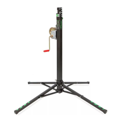
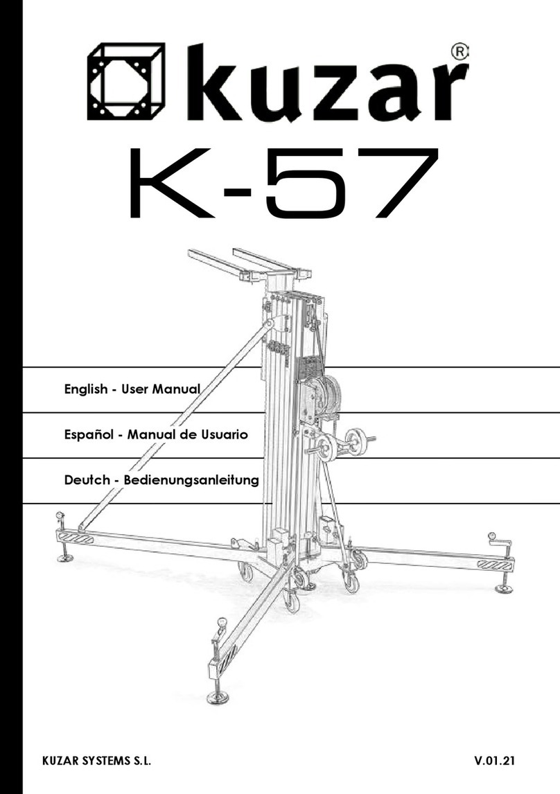
Kuzar K-52 User manual

English - User Manual
Deutch - Bedienungsanleitung
Español - Manual de Usuario
KUZAR SYSTEMS S.L. V.09.19

2
K-52
300 kg (661.4 lb)
8 m (26.24’)
Made in Spain (EU)
KUZAR SYSTEMS S.L.
C/ Ciudad de Ferrol Nº8
Pol.Ind. Fuente del Jarro
46988 Paterna - Valencia (Spain)
Manual de usuario propiedad de KUZAR SYSTEMS S.L. Deposito legal y copyright 2014.
Todos los derechos reservados.

3
Brazos de carga /
Forks
C
D
2159K
2196K
Soporte Brazos /
Forks support
1225K
Pata larga K-52 /
K-52 Long leg 1224K
Pata corta K-52 /
K-52 Short leg
B
A
A - Reenvios de poleas / Pulleys sets
B - Set piezas cabrestante / Winch set
C - Set piezas de la base / Base set
D - Set del estabilizador / Stabilizer set
1366K
1367K
1368K
1369K
Tramo 2 / Section 2
Tramo 3 / Section 3
Tramo 4 / Section 4
Tramo 1 / Section 1
Base
1371KTramo 6 / Section 6
1370K
Tramo 5 / Section 5

4
2185K
Gatillo KAT /
KAT Lock
1029K
Tornillo /
Screw
8001K
Arandela /
Washer 2138K
Taco Gatillo/
Lock rest
2156K
2157K

5
A.1
A.1 - Reenvío superior Tramo 1 Base / Upper pulley set on Section 1 Base
A.2
A.2
A.2
A
Vista en Planta superior /
Top view
A.5
A.2
A.4
2166NK
2232K
1032K 8004K 8004K
2233K
1070K
8004K
1015K
8004K
1070K
1030K
1015K
1030K
2234K
2234K
2008NK

6
A.3 - Reenvío inferior / Lower pulley set
A.2 - Reenvío superior Tramos 2 a 5/ Upper pulley set on sections 2 to 5
A.4 - Fijación nal de cable / Cable xation
1032K 8004K 8004K
2008K
2175K
2174K
1027K
1027K
1027K
1027K
8001K
8001K
8001K
8001K
8001K
8001K
1027K
1027K
A.8
A.9
1114K
1026K
1026K
9052K 8013K
8004K 7006K
1046K
1032K 8004K 8004K
2008K 2175K 2179K
1027K
1027K
8001K
8001K

7
A.6 - Freno de Inercia / Inertial break
A.7 - Tornillo jación soporte brazos /
Fixation screw for the forks support
A.8 - Taco tope barras superior / Upper stop piece
2146K/C
2144K
1026K
1004K
2145K
2143K 2142K
1030K
1030K
1043NK
8009K
8009K
7008K
1033K
2177K
8003K7002K
A.5 - Rodillo Nylon / Nylon roller
A.9 - Taco tope barras inferior / Lower stop piece
1042K
1042K
2176K

8
B
1028K
Tornillo / Screw
8003K
Arandela / Washer
7002K
Tuerca / Nut
2173NK
Placa cabrestante /
Winch support plate
1036K
Tornillo / Screw
8006K
Arandela / Washer
7001K
Tuerca / Nut
2193K
Placa tirantes /
Strut support plate 4004K
Cabrestante /
Winch
1036K Tornillo / Screw
8001K Arandela / Washer
7001K Tuerca / Nut
9052K
Cable de acero /
Steel cable

9
C
2119K
Tornillo / Screw
Nivel de Burbuja /
Spirit level
5004K Rueda /Wheel K-52
Arandela / Washer
1022K
8004K
2188K
Base K-52
2190K
Pomo transporte patas /
Transport security knob
Gatillo patas /
Security leg lock
2189LK
1028K Tornillo / Screw
8003K Arandela / Washer
7002K Tuerca / Nut
1020K Tornillo / Screw
8001K Arandela / Washer
7001K Tuerca / Nut
2137K
Tirante largo derecho /
Long right strut
2136K
Tirante largo izquierdo /
Long left strut
2136K
Tirante largo izquierdo (delantero) /
Long left strut (front position)
Tuerca / Nut
7006K

10
D
2169K
7009K
2168NK
Estabilizador completo /
Complete stabilizer kit
2170K
1015K 8009K
2171K
7010K
1041K
2172NK
8006K
1003K

11
Code/Código Description/Descripción
LISTA DE REPUESTOS / SPARE PARTS LIST
1003K Tornillo allen M8 x 16 / Allen screw M8 x 16
1004NK Tornillo cónico M5 x 12 / Conic screw M5 x 12
1015K Tornillo allen M12 x 25 / Allen screw M12 x 25
1020K Tornillo allen M8 x 25 / Allen screw M8 x 25
1022K Tornillo allen M12 x 40 / Allen screw M12 x 40
1026K Tornillo cónico M8 x 20 / Conic screw M8 x 20
1027K Tornillo especial M8 x 16 / Special screw M8 x 16
1028K Tornillo allen M10 x 30 / Allen screw M10 x 30
1029K Tornillo allen M8 x 35 / Allen screw M8 x 35
1030K Tornillo cónico M8 x 25 / Conic screw M8 x 25
1032K Tornilloespecialcabezaplana/SpecialatM12screw
1033K Tornillo rodillo nylon / Nylon runner screw
1036K Tornillo allen M8 x 30 / Allen screw M8 x 30
1041K Tornillo allen M6 x 35 / Allen screw M6 x 35
1042K Tornillo cónico M8 x 30 / Conic screw M8 x 30
1043NK Tornillo allen M14 x 200 / Allen screw M14 x 200
1046K Tornillo especial M12 x 45 / Special Screw M12 x 45
1070K Tornillo allen M12 x 50 / Allen screw M12 x 50
1114K Pletinajacióncableconargolla/Cable(withshackle)xationplate
1224K Pata corta K-52 / Short leg K-52
1225K Pata larga K-52 / Long leg K-52
1366K Tramo 1 (Base) / Section 1 (Base) (K-52)
1367K Tramo 2 / Section 2 (K-52)
1368K Tramo 3 / Section 3 (K-52)
1369K Tramo 4 / Section 4 (K-52)
1370K Tramo 5 / Section 5 (K-52)
1371K Carro aluminio Tramo 6 / Aluminium lifting carriage section 6 K-52
2008K Polea acero Ø90x12mm / Ø90x12mm Steel pulley
2008NK Polea acero Ø90x17mm / Ø90x17mm Steel pulley
2119K Niveldeburbuja/Spiritlevelindicator
2136K Tirante largo izquierdo / Long left strut
2137K Tirante largo derecho / Long right strut

12
Code/Código Description/Descripción
LISTA DE REPUESTOS / SPARE PARTS LIST
2138K TacoGatillo/Lockrest
2142K Tope tramos / Section Top
2143K Tope roscado tramos / Section screw top
2144K Rampafreno/Brakeramp
2145K Muelle / Spring
2146K/C VarillafrenoinerciadiscosØ22mm/Ø22mmInertiabrakerod
2156K Pasador / Pin
2157K Clip “R” / “R” Shape clip
2159K Brazodecarga/Liftingfork
2166NK Cubre cable polea ancha Ø90 entrada / Cable entry Ø90 wide pulley cover
2168NK Estabilizador completo K-52 / Complete stabilizer K-52
2169K Bola grande de estabilizador / Big stabilizer ball
2170K Manivela grande estabilizador / Big stabilizer handle
2171K Plato grande estabilizador / Big stabilizer plate
2172NK Esparrago estabilizador M24 x 500 / Threaded bolt M24 x 500
2173NK Placa porta-cabrestante K-52 / Winch plate K-52
2174K Macizo porta-poleas inferior / Lower pulley support piece
2175K Cubre cable polea Ø90 / Pulley cover Ø90
2176K Taco tope tramos ancho / Large stop piece
2177K Rodillo nylon grande / Large nylon roller
2179K Macizo porta-poleas superior / Upper pulley support piece
2185K GatilloKAT(v.14)/KATLock(v.14)
2188K Base Kuzar Grande (v.14) / Large Kuzar Base (v.14)
2189LK Gatillopataslargas/Longsecurityleglock
2190K Pomoaprietetransportepatas/Transportsecurityknobforlegs
2193K Placasujeccióntirantes(v.14)/Strutsupportplate(v.14)
2196K Soportebrazocarga/Forksupport
2232K Pletina hierro porta-poleas tramo 1 / Steel plate for 1st section pulley
2233K Ángulo de hierro porta-poleas tramo 1 / Steel angle for 1st section pulley
2234K Casquillo aluminio Ø25x3 Long: 29mm / Aluminium shell Ø25x3mm
4004K Cabrestante900kgManivelalarga/900kgWinchLonghandle
5004K Rueda Ø100 (blanca) / Wheel Ø100 (white)

13
Code/Código Description/Descripción
LISTA DE REPUESTOS / SPARE PARTS LIST
7001K TuercaM8autoblocante/Auto-blocknutM8
7002K TuercaM10autoblocante/Auto-blocknutM10
7006K TuercaM12autoblocante/Auto-blocknutM12
7008K TuercaautoblocanteM14/Auto-blocknutM14
7009K Tuerca M12 / Nut M12
7010K TuercaM6autoblocante/Auto-blocknutM6
8001K Arandela M8 / M8 washer
8003K Arandela M10 / M10 washer
8004K Arandela M12 / M12 washer
8006K Arandela M8 ancha / Wide M8 washer
8009K Arandela M14 / M14 washer
8013K Arandela M12 ancha / Wide M12 washer
9052K Cable K-52 6mm / Cable K-52 6mm

14
K-52
Operating Instructions - ENGLISH
1 - INTRODUCTION.
Dearuser.ThankyoupurchasingyourKuzarK-52lifter.Wehopeyouwillbeverysatis-
edwithit.
Thismanualhasbeenwrittensothatyoucanunderstandhowtoeectivelyusethelift
and most importantly, so that you can use it safely. It is important that you fully read the
manual and follow the instructions carefully before using your lift. All Kuzar lifts undergo
a very strict quality control process during their manufacture.
SothatyourliftalwaysworksproperlypleaseonlypurchaseoriginalKuzarpartsfroman
authorized distributor or dealer. The user waives all warranty rights if using parts other
than Kuzar or if the product is manipulated in any way by an unauthorized third party.
When requesting parts, please refer to the diagrams of this manual and quote the
serial number and year of manufacture located on your lifter.
2 - TECHNICAL SPECIFICATIONS.
Kuzar lifter, model K-52 has been designed for vertically lifting lighting, trussing etc in the
Professional sound and light sector. For various Kuzar supports available please refer to
our website www.kuzar.es or catalogue.
2.1-Max.load:300kg(661.4lb)
2.2-Min.load:25kg(55lb)
2.3 - Max. height: 8 m (26.24’)
2.4 - Folded height: 1.99 m (6.53’)
2.5-Worksurface:1.87x1.80m(6.13’x5.90’)
2.6 - Folded base area: 56 cm x 63 cm (1.84’ x 2.07’)
2.7-Weight:185kg(407.86lb)
2.8-Winch:900kgcertied
2.9-Cable:SteelDIN3060.Tensilestrength180kg/mm2. Anti-torsion & anti-corrosion
Ø6 mm cable diameter.
2.10-Constructionmaterial:Alluminiumproles6082T6.
2.11-Antirustprotectionprimingpaintbathedblacksteel,coveredwithcuredpolyester
dust.

15
K-52
Operating Instructions - ENGLISH
2.12 - Kuzar Automatic Trigger (KAT) on each section which automatically slots in to the
sectionsduringelevation,lockingtheminplace.
2.13 - Anchor of the legs by safety catches.
2.14-Adjustablestabilizerplatesinthelegswithnonsliprubberbasesupport.
2.15 - Spirit level for vertical alignment.
2.16-Swivelwheelsfortransportingtheliftertoitsworkingposition.
3 - SAFETY GUIDELINE.
3.1-Situatethetoweronasolidandatsurface.
3.2-Checkthatthelegsarefullyinsertedandsecuredintotheirhousingwiththesafety
locks.
3.3 - Ensure that the lifter is in a vertical position and use the spirit level located on the
baseproletocheck.Ifnecessary,adjustitsalignmentwiththeplatesbyturningthe
handle in the appropriate direction.
3.4-Checkthatthetowerislockedinitsworkingpositionwiththesafetylock.
3.5 - When used outdoors, place the tower on a hard surface and if necessary secure it
against excess wind force via cable braces.
3.6 - Do not use ladders nor lean them against the lifter.
3.7-Becarefulwithanycables,prominentobjectsetc.placedabovethetower.
3.8 - Do not stand underneath the load.
3.9 - Do not move the tower when it is elevated or loaded.
3.10-Beforeusingthetower,checktheconditionofthecable.Thismustbefreeofcuts
and frays. Never use damaged cables.
3.11 - Never dismount the winch handle or any element of the winch under any circum-
stance.
3.12-Oncethetowerisset-upinitsworkingpositionwerecommendedthewinchhan-
dleislockedtoavoidanyoneinterferingwithit.
3.13-Theminimumloadforasafeoperationofthebrakeis25kg.Thebrakewillnot
function without this minimum load.
3.14-Donotgreaseorlubricatethebrakemechanismofthewinch.
3.15 - This lift cannot lift human beings.
3.16-Fortransportationitisnecessarytoretractallprolesandlockthemwiththe
correspondingsafetylock.

16
K-52
Operating Instructions - ENGLISH
4 - OPERATION.
4.1-Placethetoweronaatandsolidsurfacewhereitisgoingtobeused.
4.2-Removethelegsfromtheirtransportsupportsandinsertthemintheirworkingpo-
sition.Checkthattheyarefullyinsertedandxedwiththeirsafetylock.
4.3 - Ensure that the lifter is in a vertical position and use the spirit level located on the
baseproletocheckthebubbleiscentred.Ifnecessary,adjustitsalignmentwiththe
stabilizer plates by turning the handle in the appropriate direction.
4.4-Changetheforkstotheirhorizontalworkingpositionandxthemwiththefastener
pins,placetheloadontheforksusingaKuzarAccessoryifnecessary,andensurethat
thetowerisonlyusedtoliftloadsvertically.Theminimumloadis25kg.
NEVER RAISE THE TOWER SECTIONS WITHOUT LOAD.
1
2 3 4 5
4.5 - Elevation:
4.5.1-EnsurethatalltheKATlocksareinthe
BLOCK position.
4.5.2 - Change the nº1 KATlocktotheLIFT position.
4.5.3-Turnthehandleclockwisetoraisethelifting
carriage of the tower.
4.5.4 - When you have reached the desired height,
xthe nº1 KATlockinbyturningthehandleanti-
clockwise.Changethenº1 KATlocktotheBLOCK
position.
4.5.5 - Change the nº2 KATlocktotheLIFT position.
4.5.6-Turnthehandleclockwisetorisethenextsectionofthetower.
4.5.7-Whenyouhavereachedthedesiredheight,xthenº2 KATlockinby
turningthehandleanti-clockwise.
Checkthatthenº2 KAT lockhasintroducedintoitscorrespondinghole.
And change the nº2 KAT locktotheBLOCK position.
4.5.8 - Repeat these steps to raise all the sections of the tower, changing all

17
K-52
Operating Instructions - ENGLISH
the KATlocksleftorderly to the LIFTpositionandturningthehandleclockwise.
WARNING: The tower can be left in any intermediate height if necessary. Just make
sure that the KAT locks are always xed and introduced. In the unlikely event of cable
breaking the KAT locks will ensure that the tower stays UP and SECURE.
Your security is our main concern.
IMPORTANT - HOW TO PLACE THE LOAD ON THE LIFTER
Always load as close to the tower as possible.
Follow the instruction of the next picture to place the load correctly, the diagram shows
the load out of the gravity center, with distances to the lifting carriage at a maximum
lifting. Notice that the maximum load diminishes according to the distance from the body
of the tower.
X1
X2
X3
X4
X5
K-52
POSITION DISTANCE LOAD PERCENTAGE
X1 30 cm 300kg 100%
X2 40 cm 285kg 95%
X3 50 cm 267kg 89%
X4 60 cm 210kg 70%
X5 70 cm 165kg 55%

18
K-52
Operating Instructions - ENGLISH
4.6 - Descent:
4.6.1-Tofoldthetowerdown,rst,turnthehandleofthewinchclockwiseto
tighten the steel cable.
4.6.2 - Once the cable is tense, pull out the nº5 KATlock,mantainitalwaysin
LIFTpositionbutkeepitout.
4.6.3-WhileyoukeeptheKATlockout,turnthehandleanti-clockwisetobring
down the corresponding section of the tower.
4.6.4 - Once the section has been brought down, release the nº5 KATlock,
and pull out the nº4 KATlock.
4.6.5-WhileyoukeepthenextKATlockout,turnthehandleanti-clockwiseto
bring down the next section.
4.6.6-Keeprepeatingthesesteps,pullingoutalltheKATlocksleftinorder
whileyouturnthehandleanti-clockwise.
4.6.7-Oncethetowerhasbeenfoldeddown,placealltheKATlocksinthe
BLOCK position.
4.7 - Transport:
Turn the handle of the stabilizers to release tension on the legs in order to pull them out.
Then, place the legs in their transport compartments located at the base of the tower.
Pullouttheforksandplacetheminverticalposition.Thetowerwillbereadyfortransport.
5 - MAINTENANCE.
5.1-Allcablesmustbecheckedregularly.Faultycablesmustbereplacedimmediately.
Do not use the lifter with faulty cables as it is potentially very dangerous. Only use DIN
3060 cables, supplied from an authorised dealer.
5.2 - The lifter is delivered ex factory completely greased. Depending on its mechanical
Use though, we recommend that the crown wheel of the winch, the pads & bushings
ofthedriveshaft,thehandlethreadandtheprolesoftheliftareperiodicallygreased.
ATTENTION:
Do not apply oil or grease to the brake mechanism. The brake discs have been pre-grea-
sed with a special heat and pressure resistant grease. To avoid malfunction to the winch

19
K-52
Operating Instructions - ENGLISH
brake, no other products must be used except the original provided by the company. It
is not necessary to grease the brake discs.
5.3 - Your lifter should be inspected at least once a year by a specialized / authorized
service centre.
5.4 - Only original Kuzar spare parts must be used to guarantee the reliability and ope-
rational safety of your lifter. The user shall lose all warranty claims if he uses anything
otherthanoriginalsparepartsormodiesthisproductinanyway.
5.5 - In case a spare part is required please indicate the reference number which can be
foundinthesparepartslistatthebackofthismanual.
6 - WARRANTY.
All Kuzar lifts come with 2 years warranty. This warranty period is from the date of pur-
chase. Kuzar will repair any defect product caused by either faulty materials or poor
workmanshipfreeofchargewithinthisperiodaslongasthepartsarettedbyanautho-
rized Kuzar dealer. Should the product have been manipulated in any way or a repair
attempted by an unauthorized dealer the warranty will be invalid. This warranty does not
cover damage occurred by improper use.
7 - CERTIFICATIONS
Kuzarreservestherighttomakeanymodication/alterationtotheliftwithoutpriornoti-
ce.Anymodication/alterationwouldbeaninnovation,intendedtoimprovetheproduct.

20
K-52
Manual de instrucciones - ESPAÑOL
1 - INTRODUCCIÓN.
Estimado usuario. Gracias por la compra de su torre elevadora Kuzar K-52. Esperamos
quede satisfecho con ella.
Estemanualhasidoescritoparaqueustedpuedaentendercómoutilizarecazmente
la torre y lo más importante, el modo para que pueda utilizarla con seguridad. Es impor-
tante que lea el manual y siga las instrucciones cuidadosamente antes de usar la torre.
Todas las torres Kuzar son sometidas a un proceso de control de calidad muy estricto
durante su fabricación. Para que su torre elevadora funcione siempre correctamente
por favor reemplazar únicamente con piezas originales Kuzar de un distribuidor o con-
cesionario autorizado. El usuario renuncia a todos los derechos de garantía si se usan
piezas que no sean Kuzar o si el producto es manipulado por un tercero no autorizado.
Al solicitar piezas, por favor consulte los dibujos de este manual así como el nú-
mero de serie y año de fabricación ubicados en el elevador.
2 - ESPECIFICACIONES TÉCNICAS.
Torre elevadora Kuzar, modelo K-52 ha sido diseñada para elevar verticalmente ilumina-
ción y las estructuras, etc. para el sector del sonido e iluminación profesional. Existen
diversos soportes disponibles Kuzar, por favor consulte nuestro catálogo o página web:
www.kuzar.es.
2.1-Max.carga:300kg(661.4lb)
2.2-Min.carga:25kg(55lb)
2.3 - Max. Altura: 8 m (26.24’)
2.4 - Altura plegada: 1.99 m (6.53’)
2.5-Superciedetrabajo:1.87x1.80m(6.13‘x5.90‘)
2.6-Superciedelabaseplegada:56cmx63cm(1.84’x2.07’)
2.7-Peso:185kg(407.86lb)
2.8-Cabrestante:900kgcerticado.
2.9-Cable:AceroDIN3060.Resistenciaalatracción180kg/mm2. Anti-torsión y anti-
corrosión de Ø6 mm.
2.10-Materialdeconstrucción:PerlesdeAluminio6082T6.
Table of contents
Other Kuzar Lifting System manuals
Popular Lifting System manuals by other brands

Reechcraft
Reechcraft PowerLift PL20 Operators safety manual

Braun
Braun NL501 Series Service manual

Maxon
Maxon 297072-01 Instruction

Ingersoll-Rand
Ingersoll-Rand BSD instructions

QUALITY LIFTS
QUALITY LIFTS Q12 Installation, operation & maintenance manual

REID LIFTING
REID LIFTING PORTAGANTRY RAPIDE US-PGRS20 Assembly & Operation guide

Tuxedo
Tuxedo TP11KC-DX Installation & operation manual

Eagle Equipment
Eagle Equipment MTP-9F manual

Vestil
Vestil A-LIFT-R instruction manual

twin busch
twin busch TW 125 M Installation, operation and maintenance manual

Ohlins
Ohlins Apex RTX Mounting instructions

Harken
Harken WingMan IN404 Specification & user manual