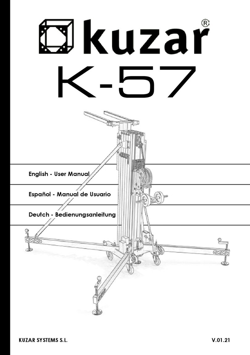
Kuzar K-30 User manual

KUZAR SYSTEMS S.L. Version.18/09
English - User Manual
Español - Manual de Usuario
Deutch - Bedienungsanleitung

2
K-30
Made in Spain (EU)
200 kg (440.93 lb)
5 m (16.40’)
KUZAR SYSTEMS S.L.
C/ Ciudad de Ferrol Nº8
Pol.Ind. Fuente del Jarro
46988 Paterna - Valencia (Spain)
Manual de usuario propiedad de KUZAR SYSTEMS S.L. Deposito legal y copyright 2014.
Todos los derechos reservados.

3
C
D
1339
1340
1341
1342
1343
Tramo 2 / Section 2
Tramo 3 / Section 3
Tramo 4 / Section 4
Tramo 5 / Section 5
Tramo 1 / Section 1
Base
2159 Brazos de carga /
Forks
2194 Soporte Brazos /
Forks support
1221
Pata larga K-30 /
K-30 Long leg
1220
Pata corta K-30 /
K-30 Short leg
B
A
A - Reenvios de poleas / Pulleys sets
B - Set piezas cabrestante / Winch set
C - Set piezas de la base / Base set
D - Set del estabilizador / Stabilizer set

4
2185
Gatillo KAT /
KAT Lock
1029
Tornillo /
Screw
8001
Arandela /
Washer 2138
Taco Gatillo/
Lock rest
Prisionero nal de cable / Cable grip
1038
2154
1038
1038
1038
1038
1038
2156
2157

5
A.1
A.1 - Reenvío superior / Upper pulley set
A.1
A.1
A.1
A
A.2 - Reenvío inferior / Lower pulley set
10263007
2007
10278001
10278001
1027
1027
1005
2140
1033
2141
1031
1030 1030
1113
1032
2007
8004
Vista en Planta superior /
Top view
A.4
2132

6
A.5 - Freno de Inercia / Inertial break
A.6 - Tornillo jación carro de hierro /
Fixation screw for iron lifting carriage
A.7 - Taco tope barras / Stop piece
2146
2144
1026
1004
2145
2143 2142
1030
1030
A.3 - Piezas sujección Tramo 1 Aluminio a Base de hierro /
Fixation piece Section 1 to Base
1034N
8009
8009
7007
1033
2141
80037002
A.4 - Rodillo Nylon / Nylon roller
1030 1030
1113
1026
2155
1026

7
B
1028
Tornillo / Screw
8003
Arandela / Washer
7002
Tuerca / Nut
2135N
Placa cabrestante /
Winch support plate
1036
Tornillo / Screw
8006
Arandela / Washer
7001
Tuerca / Nut
2191
Placa tirantes /
Strut support plate
4001
Cabrestante /
Winch
1036 Tornillo / Screw
8001 Arandela / Washer
7001 Tuerca / Nut
9030
Cable de acero /
Steel cable

8
C
2119
Tornillo / Screw
Nivel de Burbuja /
Spirit level
5003 Rueda /Wheel K-30
Arandela / Washer
1022
8004
2186
Base K-30
2190
Pomo transporte patas /
Transport security knob
Gatillo patas /
Security leg lock
2189
1028 Tornillo / Screw
8003 Arandela / Washer
7002 Tuerca / Nut
1020 Tornillo / Screw
8001 Arandela / Washer
7001 Tuerca / Nut
2137
Apoyo derecho /
Right strut
2136
Apoyo izquierdo /
Left strut
2136
Apoyo izquierdo /
Left strut
Tuerca / Nut
7006

9
D
2115
7003
2116
1006 8004
2117
8005
1012
2134
1011
7004 2133
Estabilizador completo /
Complete stabilizer kit

10
Code/Código Description/Descripción
LISTA DE REPUESTOS / SPARE PARTS LIST
1004 Tornillo cónico M5 x 12 / Conic screw M5 x 12
1005 Tornillo cónico M6 x 16 / Conic allen screw M6 x 16
1006 Tornillo allen M10 x 25 / Allen screw M10 x 25
1011 Tornillo allen M5 x 25 / Allen screw M5 x 25
1012 Tornillo allen M6 x 10 / Allen screw M6 x 10
1020 Tornillo allen M8 x 25 / Allen screw M8 x 25
1022 Tornillo allen M12 x 40 / Allen screw M12 x 40
1026 Tornillo cónico M8 x 20 / Conic screw M8 x 20
1027 Tornillo especial M8 x 16 / Special screw M8 x 16
1028 Tornillo allen M10 x 30 / Allen screw M10 x 30
1029 Tornillo allen M8 x 35 / Allen screw M8 x 35
1030 Tornillo cónico M8 x 25 / Conic screw M8 x 25
1031 Tornillo allen M5 x 20 / Allen screw M5x20
1032 Tornilloespecialcabezaplana/SpecialatM12screw
1033 Tornillo rodillo nylon / Nylon runner screw
1034N Tornillo allen M14 x 150 / Allen screw M14 x 150
1036 Tornillo allen M8 x 30 / Allen screw M8 x 30
1038 Tornillo allen sin cabeza M8 / Headless allen screw M8 x 10
1113 Pletina tope de aluminio / Alluminium stop piece
1220 Pata corta / Short leg
1221 Pata larga / Long leg
1339 Tramo 1 (Base) / Section 1 (Base)
1340 Tramo 2 / Section 2
1341 Tramo 3 / Section 3
1342 Tramo 4 / Section 4
1343 Carro aluminio Tramo 5 / Aluminium lifting carriage section 5
2007 Polea º55 / Pulley º55
2115 Bola de estabilizador M10 / Stabilizer ball M10
2116 Manivela estabilizador / Stabilizer handle
2117 Plato estabilizador º80 / Stabilizer plate º80
2119 Nivel de burbuja / Spirit level indicator
2132 Taco eje / Axel rest

11
Code/Código Description/Descripción
LISTA DE REPUESTOS / SPARE PARTS LIST
2133 Estabilizador Completo / Complete stabilizer
2134 Esparrago M18 / Threaded Bolt M18
2135N Placa portacabrestante corta (v.14) / Short winch plate K-30 (v.14)
2136 Tirante Izquierda / Left strut
2137 Tirante Derecha / Right strut
2138 Taco Gatillo / Lock rest
2140 Taco polea inferior pequeña º55 / Small lower pulley rest º55
2141 Rodillo nylon / Nylon runner
2142 Tope tramos / Section Top
2143 Tope roscado tramos / Section screw top
2144 Rampa freno / Brake ramp
2145 Muelle / Spring
2146 Freno de carro / Carriage break
2154 Prisionero cable / Cable clamp
2155 Taco tramo base pequeño / Base section rest
2156 Pasador / Pin
2157 Clip “R” / “R” Shape clip
2159 Brazo de carga / Lifting fork
2185 Gatillo KAT (v.14) / KAT Lock (v.14)
2186 Base Kuzar pequeña (v.14) / Small Kuzar base (v.14)
2189 Gatillo patas / Security leg lock
2190 Pomo apriete transporte patas / Transport security knob for legs
2191 Placa sujección tirantes (v.14) / Strut support plate (v.14)
2194 Soporte brazo carga / Fork support
3007 Eje 12 x 57 / 12 x 57 Axel
4001 Cabrestante 450kg / 450kg Winch
5003 Rueda º100 (azul) / Wheel º100 (blue)
7001 Tuerca M8 autoblocante / Auto-block nut M8
7002 Tuerca M10 autoblocante / Auto-block nut M10
7003 Tuerca M10 / Nut M10
7004 Tuerca M5 autoblocante / Auto-block nut M5
7006 Tuerca M12 autoblocante / Auto-block nut M12
7007 Tuercamariposaautoblocante/Auto-blockButterynutM12

12
Code/Código Description/Descripción
LISTA DE REPUESTOS / SPARE PARTS LIST
8001 Arandela M8 / M8 washer
8003 Arandela M10 / M10 washer
8004 Arandela M12 / M12 washer
8005 Arandela M6 ancha / Wide M6 washer
8006 Arandela M8 ancha / Wide M8 washer
8009 Arandela M14 / M14 washer
9030 Cable K-30 5mm / Cable K-30 5mm

13
K-30
Operating Instructions - ENGLISH
1 - INTRODUCTION.
Dear user. Thank you purchasing your Kuzar K-30 lifter. We hope you will be very satis-
edwithit.
This manual has been written so that you can understand how to effectively use the lift
and most importantly, so that you can use it safely. It is important that you fully read the
manual and follow the instructions carefully before using your lift. All Kuzar lifts undergo
a very strict quality control process during their manufacture.
So that your lift always works properly please only purchase original Kuzar parts from an
authorized distributor or dealer. The user waives all warranty rights if using parts other
than Kuzar or if the product is manipulated in any way by an unauthorized third party.
When requesting parts, please refer to the diagrams of this manual and quote the
serial number and year of manufacture located on your lifter.
2 - TECHNICAL SPECIFICATIONS.
Kuzar lifter, model K-30 has been designed for vertically lifting lighting, trussing etc in the
Professional sound and light sector. For various Kuzar supports available please refer to
our website www.kuzar.es or catalogue.
2.1 - Max. load: 200 kg (440.93 lb)
2.2 - Min. load: 25 kg (55 lb)
2.3 - Max. height: 5 m (16.40’)
2.4 - Folded height: 1.56 m (5.12’)
2.5 - Transport surface: 1,56x0.48x0.46m (5.12’x1.57’x1.51’).
2.6 - Shipping dimension: 1,60x0.49x0.49m (5.25’x1.61’x1.61’).
2.5 - Work surface: 1.80 x 1.69 m (5.90’ x 5.54’)
2.6 - Folded base area: 46 cm x 48 cm (1.51’ x 1.57’)
2.7 - Weight: 103 kg (227 lb)
2.8-Winch:450kgcertied
2.9 - Cable: Steel DIN 3060. Tensile strength 180 kg/mm2. Anti-torsion & anti-corrosion
Ø5 mm cable diameter.
2.10-Constructionmaterial:Alluminiumproles6082T6.
2.11 - Antirust protection priming paint bathed black steel, covered with cured polyester
dust.

14
K-30
Operating Instructions - ENGLISH
2.12 - Kuzar Automatic Trigger (KAT) on each section which automatically slots in to the
sections during elevation, locking them in place.
2.13 - Anchor of the legs by safety catches.
2.14 - Adjustable stabilizer plates in the legs with nonslip rubber base support.
2.15 - Spirit level for vertical alignment.
2.16 - Swivel wheels for transporting the lifter to its working position.
3 - SAFETY GUIDELINE.
3.1-Situatethetoweronasolidandatsurface.
3.2 - Check that the legs are fully inserted and secured in to their housing with the safety
locks.
3.3 - Ensure that the lifter is in a vertical position and use the spirit level located on the
baseproletocheck.Ifnecessary,adjustitsalignmentwiththeplatesbyturningthe
handle in the appropriate direction.
3.4 - Check that the tower is locked in its working position with the safety lock.
3.5 - When used outdoors, place the tower on a hard surface and if necessary secure it
against excess wind force via cable braces.
3.6 - Do not use ladders nor lean them against the lifter.
3.7 - Be careful with any cables, prominent objects etc. placed above the tower.
3.8 - Do not stand underneath the load.
3.9 - Do not move the tower when it is elevated or loaded.
3.10 - Before using the tower, check the condition of the cable. This must be free of cuts
and frays. Never use damaged cables.
3.11 - Never dismount the winch handle or any element of the winch under any circum-
stance.
3.12 - Once the tower is set-up in its working position we recommended the winch han-
dle is locked to avoid anyone interfering with it.
3.13 - The minimum load for a safe operation of the brake is 25 kg. The brake will not
function without this minimum load.
3.14 - Do not grease or lubricate the brake mechanism of the winch.
3.15 - This lift cannot lift human beings.
3.16-Fortransportationitisnecessarytoretractallprolesandlockthemwiththe
corresponding safety lock.

15
K-30
Operating Instructions - ENGLISH
4 - OPERATION.
4.1-Placethetoweronaatandsolidsurfacewhereitisgoingtobeused.
4.2 - Remove the legs from their transport supports and insert them in their working po-
sition.Checkthattheyarefullyinsertedandxedwiththeirsafetylock.
4.3 - Ensure that the lifter is in a vertical position and use the spirit level located on the
baseproletocheckthebubbleiscentred.Ifnecessary,adjustitsalignmentwiththe
stabilizer plates by turning the handle in the appropriate direction.
4.4-Changetheforkstotheirhorizontalworkingpositionandxthemwiththefastener
pins, place the load on the forks using a Kuzar Accessory if necessary, and ensure that
the tower is only used to lift loads vertically. The minimum load is 25 kg.
NEVER RAISE THE TOWER SECTIONS WITHOUT LOAD.
1
2 3 4 5
4.5 - Elevation:
4.5.1 - Ensure that all the KAT locks are in the
BLOCK position.
4.5.2 - Change the nº1 KAT lock to the LIFT position.
4.5.3 - Turn the handle clockwise to raise the lifting
carriage of the tower.
4.5.4 - When you have reached the desired height,
xthe nº1 KAT lock in by turning the handle anti-
clockwise. Change the nº1 KAT lock to the BLOCK
position.
4.5.5 - Change the nº2 KAT lock to the LIFT position.
4.5.6 - Turn the handle clockwise to rise the next section of the tower.
4.5.7-Whenyouhavereachedthedesiredheight,xthenº2 KAT lock in by
turning the handle anti-clockwise.
Check that the nº2 KAT lock has introduced in to its corresponding hole.
And change the nº2 KAT lock to the BLOCK position.
4.5.8 - Repeat these steps to raise all the sections of the tower, changing all
the KAT locks left orderly to the LIFT position and turning the handle clockwise.

16
K-30
Operating Instructions - ENGLISH
WARNING: The tower can be left in any intermediate height if necessary. Just make
sure that the KAT locks are always xed and introduced. In the unlikely event of cable
breaking the KAT locks will ensure that the tower stays UP and SECURE.
Your security is our main concern.
4.6 - Descent:
4.6.1-Tofoldthetowerdown,rst,turnthehandleofthewinchclockwiseto
tighten the steel cable.
4.6.2 - Once the cable is tensed, pull out the nº5 KAT lock, mantain it always
in LIFT position but keep it out.
4.6.3 - While you keep the KAT lock out, turn the handle anti-clockwise to bring
down the corresponding section of the tower.
4.6.4 - Once the section has been brought down, release the nº5 KAT lock,
and pull out the nº4 KAT lock.
4.6.5 - While you keep the next KAT lock out, turn the handle anti-clockwise to
bring down the next section.
4.6.6 - Keep repeating these steps, pulling out all the KAT locks left in order
while you turn the handle anti-clockwise.
4.6.7 - Once the tower has been folded down, place all the KAT locks in the
BLOCK position.
4.7 - Transport:
Turn the handle of the stabilizers to release tension on the legs in order to pull them out.
Then place the legs in their transport compartments located at the base of the tower. Pull
out the forks and place them in vertical position. The tower will be ready for transport.
5 - MAINTENANCE.
5.1 - All cables must be checked regularly. Faulty cables must be replaced immediately.
Do not use the lifter with faulty cables as it is potentially very dangerous. Only use DIN
3060 cables, supplied from an authorised dealer.
5.2 - The lifter is delivered ex factory completely greased. Depending on its mechanical
Use though, we recommend that the crown wheel of the winch, the pads & bushings
ofthedriveshaft,thehandlethreadandtheprolesoftheliftareperiodicallygreased.

17
K-30
Operating Instructions - ENGLISH
ATTENTION:
Do not apply oil or grease to the brake mechanism. The brake discs have been pre-grea-
sed with a special heat and pressure resistant grease. To avoid malfunction to the winch
brake, no other products must be used except the original provided by the company. It
is not necessary to grease the brake discs.
5.3 - Your lifter should be inspected at least once a year by a specialized / authorized
service centre.
5.4 - Only original Kuzar spare parts must be used to guarantee the reliability and ope-
rational safety of your lifter. The user shall lose all warranty claims if he uses anything
otherthanoriginalsparepartsormodiesthisproductinanyway.
5.5 - In case a spare part is required please indicate the reference number which can be
found in the spare parts list at the back of this manual.
6 - WARRANTY.
All Kuzar lifts come with 2 years warranty. This warranty period is from the date of pur-
chase. Kuzar will repair any defect product caused by either faulty materials or poor
workmanshipfreeofchargewithinthisperiodaslongasthepartsarettedbyanautho-
rized Kuzar dealer. Should the product have been manipulated in any way or a repair
attempted by an unauthorized dealer the warranty will be invalid. This warranty does not
cover damage occurred by improper use.
7 - CERTIFICATIONS
Kuzarreservestherighttomakeanymodication/alterationtotheliftwithoutpriornoti-
ce.Anymodication/alterationwouldbeaninnovation,intendedtoimprovetheproduct.

18
K-30
Manual de instrucciones - ESPAÑOL
1 - INTRODUCCIÓN.
Estimado usuario. Gracias por la compra de su torre elevadora Kuzar K-30. Esperamos
quede satisfecho con ella.
Estemanualhasidoescritoparaqueustedpuedaentendercómoutilizarecazmente
la torre y lo más importante, el modo para que pueda utilizarla con seguridad. Es impor-
tante que lea el manual y siga las instrucciones cuidadosamente antes de usar la torre.
Todas las torres Kuzar son sometidas a un proceso de control de calidad muy estricto
durante su fabricación. Para que su torre elevadora funcione siempre correctamente
por favor reemplazar únicamente con piezas originales Kuzar de un distribuidor o con-
cesionario autorizado. El usuario renuncia a todos los derechos de garantía si se usan
piezas que no sean Kuzar o si el producto es manipulado por un tercero no autorizado.
Al solicitar piezas, por favor consulte los dibujos de este manual así como el nú-
mero de serie y año de fabricación ubicados en el elevador.
2 - ESPECIFICACIONES TÉCNICAS.
Torre elevadora Kuzar, modelo K-30 ha sido diseñada para elevar verticalmente ilumina-
ción y las estructuras, etc. para el sector del sonido e iluminación profesional. Existen
diversos soportes disponibles Kuzar, por favor consulte nuestro catálogo o página web:
www.kuzar.es.
2.1 - Max. carga: 200 kg (440.93 lb)
2.2 - Min. carga: 25 kg (55 lb)
2.3 - Max. Altura: 5 m (16.40’)
2.4 - Altura plegada: 1.56 m (5.12’)
2.5 - Dimensiones torre plegada: 1,56x0.48x0.46m (5.12’x1.57’x1.51’).
2.6 - Dimensiones de caja transporte: 1,60x0.49x0.49m (5.25’x1.61’x1.61’).
2.7-Superciedetrabajo:1.80x1.69m(5.90‘x5.54‘)
2.8-Superciedelabaseplegada:46cmx48cm(1.51’x1.57’)
2.9 - Peso: 103 kg (227 lb)
2.10-Cabrestante:450kgcerticado.

19
K-30
Manual de instrucciones - ESPAÑOL
2.11 - Cable: Acero DIN 3060. Resistencia a la tracción 180 kg/mm2. Anti-torsión y anti-
corrosión de Ø5 mm.
2.12-Materialdeconstrucción:PerlesdeAluminio6082T6.
2.13 - Acero con pintura de imprimación negra y protección anti-óxido, cubiertos de
polvo de poliéster al horno.
2.14 - Gatillo Automático de Kuzar (KAT) colocado en cada sección bloquea el movi-
miento descendente de la torre, este se introduce en cada ranura durante la elevación.
2.15 - Anclaje de las patas por gatillos de seguridad.
2.16 - Estabilizadores ajustables en las patas con apoyo antideslizante de goma.
2.17 - Nivel de burbuja para ajustar la vertical de la torre.
2.18 - Ruedas giratorias para transporte.
3 - GUÍA PARA USO SEGURO.
3.1-Ponerlatorresobreunasuperciesólidayplana.
3.2 - Comprobar que las patas estén completamente insertadas en su compartimento y
jadasporelgatillodeseguridad.
3.3 - Asegúrese de que la torre está en una posición vertical, compruébelo haciendo
usodelniveldeburbujasituadoenelperlbase.Siesnecesario,ajustarsuverticalidad
mediante los estabilizadores, girando la manivela en la dirección apropiada.
3.4 - Comprobar que la torre se bloquea en su posición de trabajo con los gatillos de
seguridad KAT.
3.5-Cuandoseusaalairelibre,colocarlatorreenunasuperciesólidaysiesnecesa-
rio asegurarla contra la fuerza excesiva del viento por medio de tirantes de cable.
3.6 - No utilice escaleras ni las apoye en la torre.
3.7 - Tenga cuidado con los cables, los objetos prominentes etc. situados por encima
de la torre.
3.8 - No permanezca debajo de la carga.

20
K-30
Manual de instrucciones - ESPAÑOL
3.9 - No mover la torre si está elevada o con carga.
3.10-Antesdeutilizarlatorre,vericarelestadodelcable.Éstedebeestarlibrede
cortes y desgastes. No utilice nunca cables dañados.
3.11 - Nunca desmontar la palanca del cabrestante o cualquier elemento del cabrestan-
te bajo ninguna circunstancia.
3.12 - Una vez que la torre está puesta a punto en su posición de trabajo es recomenda-
ble que la palanca del cabrestante quede bloqueada para evitar cualquier interferencia
con la misma.
3.13 - La carga mínima para un funcionamiento seguro del freno es 25 kg. El freno no
funcionará sin esta carga mínima.
3.14 - No engrasar ni lubricar el mecanismo de freno del cabrestante.
3.15 - Este elevador no puede utilizarse para elevar personas.
3.16 - Para el transporte hay que bajar todos los tramos y bloquearlos con el bloqueo de
seguridad correspondiente.
4 - OPERACIÓN.
4.1-Coloquelatorreenlazonadetrabajo,sobreunasupercieplanaysólida.
4.2 - Desmonte las patas de sus soportes e insertarlas en su posición de trabajo.
Compruebequeesténcompletamenteinsertadasyjadasconelgatillodeseguridad.
4.3 - Asegurarse de que el elevador está en posición vertical, para ello, servirse del
nivel de burbuja situado en la base, y comprobar que la burbuja está centrada. Si es
necesario, ajuste la verticalidad de la torre con los estabilizadores, girando la manivela
en la dirección apropiada.
4.4-Coloquelosbrazosdecargadelatorreenposiciónhorizontaldetrabajoyjelos
con los pasadores y clips de seguridad. Coloque un Accesorio Kuzar si se requiere, y
asegurarse de que la torre sólo se utiliza para levantar cargas en sentido vertical.
La carga mínima es de 25 kg. NO ELEVE LA TORRE SIN CARGA.
Table of contents
Languages:
Other Kuzar Lifting System manuals
Popular Lifting System manuals by other brands

Hillrom
Hillrom Liko Golvo 7000 Series Service manual

Genie
Genie GTH-4013 EX Operator's manual

GEDA
GEDA AB 450 Assembly and operating manual

Bolton Tools
Bolton Tools HP-L4G Installation, operation & maintenance manual

Efco
Efco SWAPLOADER SL-518 Parts and operation manual

ARJO HUNTLEIGH
ARJO HUNTLEIGH MAXI LITE Instructions for use