Lalizas 71327 Instruction Manual

71327-SELF-CONTAINED BREATHING APPARATUS 6L SOLAS/MED
&
INSTRUCTIONS OF USE
71328-SELF-CONTAINED BREATHING APPARATUS 9L SOLAS/MED
0098
LALIZAS

1. Introduction
1.1 General Description of the product
1.2 Getting familiar with the equipment - Short Description
The new LALIZAS Respiratory Protective Device (of types 71327 & 71328) is a Self-contained open-circuit compressed air breathing apparatus with positive pressure full face mask. It is
an Apparatus for fire-fighting of Type 2 tested according to EN 137 (2006) and EN 136 (1998) including AC (1999) and AC (2003), ISO 23269-2:2011.Certified according latest provisions
of MED Directive 2014/90 and SOLAS requirements.
Approved for use as self-contained compressed air breathing apparatus of fire-fighter's outfit.
The apparatus is not for use in accidents with cargoes.
WARNING:
- It is not a diving apparatus!
- It is strongly recommended that the Apparatus is used by well- trained personnel and not by untrained users.
The Lalizas Self-Contained Breathing Apparatus Models (71327 & 71328) are similar products, as their main structure and operation is the same, while the only difference is in the used
cylinders providing different rated duration to the products. The Breathing Apparatus is sufficiently robust to withstand the rough usage it is likely to receive, and is designed so as to have
no protruding parts or sharp edges likely to be caught on projections in narrow passages or to be in contact with the wearer. It is designed to ensure its function in any orientation. All
materials used in the construction of the apparatus have adequate resistance to deterioration by heat and adequate mechanical strength. All demountable connections are readily
connected and secured by hand.
The product consists of six main components as described in short below:
a) Back frame: Incorporates donning cushion harness for convenient fitting, adjustable cylinder holding Velcro webbing and a rubber pad for better and stable placement of cylinder. It is
designed to allow the user to don and doff the apparatus quickly and easily without assistance and is adjustable, without slipping inadvertently. The back frame structure bears two grooves
for the high and medium pressure hoses of the pressure regulator to run in (Figure 1).
b) First Stage Regulator: The first stage regulator incorporates two pneumatic hoses, a reliable pressure indicator and a warning whistle. The pressure indicator, which is positioned to
enable to be read conveniently by wearer, shows the pressure in the pressure vessel on opening the valve, to ensure that the pressure is monitored. The Pressure Indicator is graduated
from zero mark up to 40Mpa (400Bar) and enables the wearer to estimate the pressure to within 1Mpa(10bar). It bears a fluorescent dial that allows clear reading of the pressure even in
intense dark, and a non-splintering window. The Warning Whistle is so designed that when pressure reduces below 50-60bar, it operates providing a continuous sound of pressure
level>90dB (A), warning the user that the air is dropping down. Moreover, the First Stage Regulator bears a connecting thread for the cylinder valve, which is G5/8 according to EN144-2.
For increased safety a relief valve is also incorporated (Figure 2).
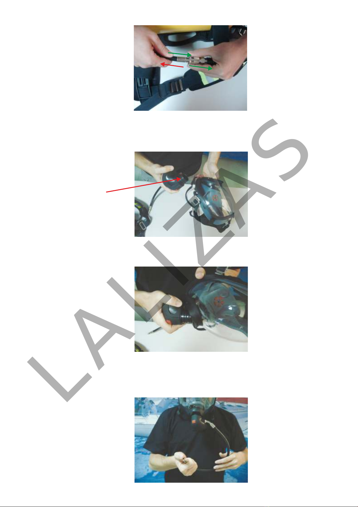
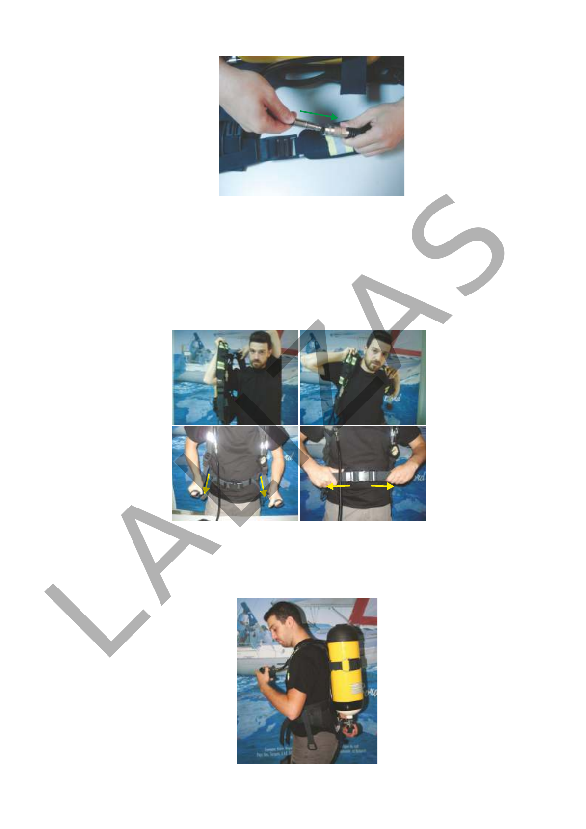
c) Second Stage Regulator: The second stage regulator consists of an “on demand'' valve and a pneumatic hose (Figure 3 ). The pneumatic hose is equipped with a fast joint for easy
assembly with the first stage regulator hose. The “on demand'' valve is so designed that can be assembled with the face piece as a plug-in interface (Figure 3). The ''on demand'' valve is
equipped with ON & OFF buttons in order to allow the user to stop or start the air supply. Using these buttons the user can stop the air supply and remove the valve from the face piece while
the cylinder valve is still open (Figure 1). This special structure does not allow the provided breathing-air to escape, while it provides the user with the possibility to re-attach the “on
demand valve” to the face piece –at all times- and re-use the device without any special procedure except just breathing. Breathing will produce under pressure inside the face mask that
will force the on ''demand'' valve to open and provide breathing air again.
d) Face piece (Figure 4): The face piece is classified as Mask of Class 3+ for Special Use per EN 136:1998 + AC (2003) and as instructed in the last version of Maritime Equipment
Directive 96/98/EC. The mask is temperature, flammability and thermal radiation resistant as well as it is leak tight and consists of:
1. Introduction
1.1 General Description of the product
1.2 Getting familiar with the equipment- Short Description
1.3 Structure of the Product
1.4 Apparatus Duration
1.5 Air quality of the equipment
1.6 Operation of Self-Contained Breathing Apparatus
1.6.1 Checks prior to Use
1.6.2 Fitting & Use
1.6.3 Doffing Procedure
1.6.4 After Use Procedure
1.7 Maintenance and Service Instructions
1.7.1 Cleaning, Disinfecting, Drying (A)
1.7.2 Visual Inspection (B)
1.7.3 Service (C)
1.7.4 Inspection Intervals
1.7.5 Function Test (E)
INDEX
1.8 Transportation and Storage
1.8.1 Transportation
1.8.2 Storage
1.8.3 Safety Notification
1.8.4 Life Expectancy
1.9 Technical Data of Self Contained Breathing Apparatus
SOLAS/MED 71327 & 71328
IMPORTANT NOTICE !In case you don't use LALIZAS original air cylinder for this device
Ensure that the air cylinder placed on the device is compatible and satisfies the following conditions:
The air cylinder shall be designed in accordance with national regulations.
The volume of air contained in the air cylinder shall be at least 1200 liter.
The compressed air cylinder markings shall include the charging pressure, capacity and the stamp of the authorized inspection body.
The complete apparatus shall undergo practical performance tests under realistic conditions to check for imperfections.
LALIZAS

OFF button
ON button
Pneumatic
hose fast joint
Cylinder
Cylinder valve
Grooves for the high
and medium pressure
hoses of the pressure
regulator
Pressure
gauge & whistle
Thread G5/8
First stage
regulator
relief valve
Figure 1 SCBA components.
a) Back frame assembled with first stage regulator, second stage regulator & face piece.
b) Back frame assembled with first stage regulator, second stage regulator, face piece & cylinder.
Rubber
protection
cover
Thread G5/8
First stage
regulator
relief valve
Figure 2 First stage regulator Figure 3 Second stage regulator
On demand
valve
Plug in
interface
e) Cylinder: For 71327 SCBA Model, a metallic cylinder of 6L and working pressure of 300bar, tested according to European Standard EN 1964-1 “Transportable gas cylinders.
Specification for the design and construction of refillable transportable seamless steel gas cylinders of water capacities from 0,5 litre up to and including 150 litres” and Certified under
Pressure Equipment Directive (PED) 97/23/EC as amended as well as under Transport Equipment Directive (TPED) 2010/35/EC, is used.
For 71328 SCBA Model, a composite cylinder of 9L, which has a working pressure of 300bar, tested according to European Standard EN 1975 “Transportable gas cylinders. Specification
for the design & construction of refillable transportable seamless aluminium and aluminium alloy gas cylinders of capacity from 0.5 litre up to 150 litre” & EN 12245 “Transportable gas
cylinders- Fully wrapped composite cylinders” and certified under Pressure Equipment Directive (PED) 97/23/EC as amended, is used. The pressure vessel outlet connection is designed
per EN 144-1 i.e. the Cylinder thread for both models is 18x1, 5mm.
Both types of cylinders are coloured per the Colour Coding System as instructed for breathing air by EN 1089-3:2001 “Transportable gas cylinders- Gas Cylinder Identification (excluding
LPG)- Part 3: Colour Coding.”
f) Pressure Vessel Valve (Figure 1): The cylinder valve that is used for both Self-Contained Breathing Apparatus Models (71327 & 71328), is designed in accordance with EN 144-1
“Respiratory Protective Devices- Gas Cylinder Valves- Thread Connections for Inlet Connector” and EN 144-2 “Respiratory Protective Devices- Gas Cylinder Valves-Outlet Connections”.
More specifically, the inlet and outlet connections on the pressure vessel valve are respectively in accordance with the requirements given in EN 144-1 for the inlet connection (M18X 1,
5mm) and EN 144-2 for the outlet connection (G5/8). This valve has a Working Pressure of 30MPa, while it bears a relief valve. The cylinder valve is equipped with a convenient in use
rubber knob and is so arranged that the wearer can operate it while wearing the apparatus. It is also protected against blockage and transmission of particulate matter that may be
contained in the compressed air and is so designed that the valve spindle cannot be completely unscrewed from the assembly during normal operation.
The LALIZAS Self-Contained Breathing Apparatus Models (71327 & 71328) are packed in heavy duty plastic carrying suitcases which provide high impact resistance that protects the
product in case of shock and drop (Figure 5). However, it is recommended to handle them with care.
a. A visor (designed to provide a wide field of vision, to be attached in a reliable and gas-tight manner to the faceblank and to be resistant to scratching and mist covering),
b. A speech diaphragm (protected against mechanical damage),
c. An exhalation valve (that works well in all orientations and is protected against dirt and mechanical damage),
d. A plug-in interface for the insertion of the “on demand” valve (readily connected and secured by hand and not possible to be connected to a thread, assuring correct and reliable
connection between the facepiece and other parts of the equipment),
e. Rubber straps (designed so that the full face mask can be donned and removed easily, while they are adjustable so as to hold the full face mask firmly and comfortably in position),
f. A sealing edge (that in combination with the high quality rubber straps ensure high fitting/ sealing regardless the face structure. It is unlikely that the requirements for leakage will be
achieved if facial hair or spectacle side arms pas under facial seal!)
g. A head net.
All components which are integral with the face mask, are of high quality and ergonomic design so as to serve in the best way a combination of well-fitting and easy-use of the device. Care
has been taken so that materials that may come in contact with the wearer's skin are not likely to cause irritation or have any adverse effect to health.
(a)
(b)
LALIZAS

Figure 5 Suitcases
1.3 Structure of the Product
The Self-Contained Breathing Apparatus is a light weight (71327 Model has a weight of 15kg & 71328 has a weight of 12kg) and highly comfortable apparatus that can provide respiratory
protection to the wearer for approximately (71327 Model: 45min & 71328 Model: 60min) in a hazardous environment. The given duration has been estimated based on an average
consumption of 40L/min and fully charged cylinder (Refer to Para. 1.4 Apparatus Duration).
The Self-Contained Breathing Apparatus (71327 & 71328) is composed of an anatomic back frame with harness for perfect and easy donning. Both back frame and harness are flame
retardant, waterproof and antistatic.
In both cases, the cylinder is connected to the back frame with a cylinder valve, designed according to EN 144-1 and a working pressure of 300bar. The cylinder valve is equipped with a
relief valve. It is connected to a first stage regulator which will decrease the high pressure of 300bar to a constant Pressure of ≈7bar and a flow of >350L/min. The first stage regulator is
also equipped with a relief valve that will open when the air pressure becomes greater than 11bar. From the first stage regulator the air is diverted into two tubes one of high pressure (WP
300Bar) and one of medium pressure (WP 20Bar). The high pressure tube – which is mounted within a tube of medium pressure for protection reasons – is attached to a warning whistle
and a pressure gauge. This tube is under the exact pressure of the cylinder when the cylinder's valve is open. The warning whistle is so designed that when pressure reduces below 50-
60bar, it operates providing a continuous sound of sound pressure level of >90dB (A), warning the user that the air is dropping down. The medium pressure tube is under pressure of 7bar
and is connected via a fast joint to the second stage regulator (“on demand'' valve) and the full face mask. The joint of the second stage regulator to the face mask provides a capability of
rotation by 360º for easier connection and more comfortable fitting. A plug-in interface is used to connect the “on demand” valve to the face mask.
1.4 Apparatus Duration
The working duration of 45min and 60min of the Self-Contained Apparatus 71327 and 71328 respectively was estimated for an average breathing air consumption of 40L/min in ambient
temperature and fully charged cylinders. However, the actual consumption might vary due to the following affecting factors:
a) Workload: Adverse work conditions can cause increase of breathing rate and as a result increase of consumption.
b) Physical fitness of the wearer: A bad physical fitness of the wearer can affect/ increase the air consumption.
c) Inconvenience in movement: Heavy and restrictive clothing demand bigger effort in movement and this would lead to increased air consumption.
d) Emotional stress and fatigue can also affect the duration of the devices.
1.5 Air quality of the equipment
The quality of breathing air used for filling the Self-Contained Breathing Apparatus conforms to EN 12021- “Respiratory protective devices - Compressed Air for breathing apparatus”. The
concentration limits of the breathing air components are described in the table below:
Table. 1 Concentration Limits of Breathing Air Components
Element
Oxygen
Lubricants
Odoure & Taste
Carbon dioxide
Carbon monoxide
Water
Content
21±1%
3
Droplets or mist ≤0,5ml/m
Without
3
≤500ml/m
3
≤15ml/m
No free liquid water
Maximum water content of air at atmospheric pressure
Nominal
Pressure
Bar
Maximum water content
of air at atmospheric
3
pressure mg/m
40 to 200
>200
50
35
Figure 4 Face piece
Visor
Lock button
Plug in
interface
Exhalation
valve
Head net
Rubber straps
Facial seal
Each SCBA shall be used together with an approved lifeline as part of the fire-fighters outfit according to FSS Code Ch.3.2.1.3. This lifeline to be capable of being attached by means of a
snap-hook to the harness of the apparatus or to a separate belt in order to prevent the breathing apparatus becoming detached when the lifeline is operated.
LALIZAS

c) Then push the “OFF'' button of the Second Stage Regulator (Figure 1 & Figure 7).
Figure 7 Closing the air supply by the ''OFF'' button of the second stage regulator
d) Open the Cylinder Valve until you hear the whistle sound and see the gauge indication stabilizing (Figure 1 & Figure 8). The indication must always be equal or more than 80% of
the rated filling pressure (300bar),so be between 240-300bar. The indication might vary ±10% depending on the environmental Temperature. Close the Cylinder Valve. Keep
checking the pressure gauge for 60 sec. If after 60sec the pressure drop is less or equal to 20dar, this means that the whole system is leak-tight. If the pressure drop in 60sec is more
than 20bar, send the SCBA for service to a LALIZAS authorized Service Station.
Figure 8 Opening the cylinder valve
e) After checking leak-tightness bring the Second Stage Regulator in mouth and inhale to check the operability of the “on demand'' valve (Figure 9). After inhaling the air pressure
will drop causing the whistle to sound again. Check the pressure gauge indication to be approximately 50 bar when the whistle sounds (Figure 9).
Figure 9 ''ON DEMAND'' valve operability check
Figure 6 Detaching the Second Stage Regulator from the Face Piece
1.6 Operation of Self-Contained Breathing Apparatus
1.6.1 Checks prior to Use
Every Self-Contained Breathing Apparatus is packed in ready for use condition. However, a brief check is strongly recommended, to ensure the good operating condition of the
equipment before use. To conduct this test, the next steps are to be followed:
a) Remove the Self-Contained Breathing Apparatus from the suitcase.
b) Push the lock button of the face piece and detach the Second Stage Regulator from the Face Piece ( Figure 4 & Figure 6).
LALIZAS

g) Check the good condition of the Second Stage Reducer O-ring as well as the good condition of the face piece visor and sealing edge for physical damages (Figure 11).
Figure 11 Visual checking of second stage reducer and face mask
O-ring of second
stage reducer
h) Assemble the second stage regulator with the face piece and don the assembled face piece on your head (Figure 12).
Figure 12 Assembly of the second stage regulator with the face piece
i) Plug the tube entrance with your finger and inhale. The face piece should deform towards your face as a sign of face piece leak tightness (Figure 13). In case that any
deficiency is noticed, send the product to a LALIZAS authorized Service Station.
Figure 13 Face piece leak tightness test
f) When the pressure gauge indicator becomes Zero, detach the Second Stage Regulator from the first stage regulator by the fast joint (Figure 10).
Figure 10 Detaching the Second Stage Regulator from the first stage regulator by the fast joint
3
1
2
LALIZAS

1.6.2 Fitting & Use
After conducting the “Brief Check'' as instructed in Paragraph 1.6.1 , follow the donning methodology as described below:
a) Harness: Don the apparatus like you wear a Jacket. Make sure no harness or hose is twisted. Adjust the shoulder straps for a tight but comfortable fit. Close the buckle of the
waist belt and fasten the strap in a comfortable way (Figure 15).
12
34
Figure 15 Donning the back frame
b) Cylinder valve: Push the “OFF'' button of the second stage Regulator (Figure 1 & Figure 7)
c) Open slowly the cylinder valve by turning counterclockwise until it is fully open. Listen the whistle sound and check the pressure gauge indication to be equal or more than
80% of the rated filling pressure, i.e. 240-300bar (Figure 16).
Figure 16 Vessel pressure checking
WARNING: TAKE EXTRA CARE TO HAVE THE CYLINDER VALVE FULLY OPENED DURING USE!
j) Doff the face piece and reassemble the second stage regulator with the first stage regulator by the fast joint (Figure 14). The Self-Contained Breathing Apparatus is now
readily checked and it can be either used or packed for storage.
Figure 14
Assembling the Second Stage Regulator with the first stage regulator by the fast joint.
LALIZAS

Figure 19
Insert the face piece on your face to fit the sealing edge
and use the head net loop to place the head-net over the head
Figure 20 Tighten the side straps
d) Face mask:
In order to fit the Full face Mask, you have to follow the steps as below:
I. Fully extend the face piece straps (Figure 17).
II. Place the lower strap over your head (Figure 17).
III. Pull the head-net on top of the face piece (Figure 18).
IV. Insert the face piece on your face to fit the sealing edge and use the head net loop to place the head-net over the head (Figure 19).
V. Tighten the side straps to achieve a tight and comfortable fit. Notice: DO NOT over tight as this can distort the face seal (Figure 20).
VI. Breathe freely.
Figure 17
Extend the rubber straps and place
the lower strap over your head.
Figure 18
Pull the head-net on top of the face piece.
LALIZAS

c) Apparatus: Release the waist-belt, slacken the shoulder straps and remove the apparatus (Figure 23).
4
3
2
1
Figure 23
Release waist belt, shoulder straps and doff the apparatus
1.6.3 Doffing Procedure
a) Cylinder valve: Check how much air is left & close the cylinder valve (Figure 16). If the air is less than 80% of the rated filling pressure (i.e. 240-300bar) the cylinder needs to be
refilled.
b) Face piece: Pull the metal buckles forward to release the head-net straps. Remove the face piece.
Figure 22 Release the rubber straps and doff the face piece
e) Facemask seal check: While breathing, take a breath and hold it. Feel the air flow stopping and then insert your finger in the face-piece seal, as shown in (Figure 21). This
action should force the demand valve to provide steady flow again. Remove the finger from face piece seal and allow the face piece to seal again.
Figure 21 Face Seal Check Method
f) Ambient air breathing: Press the face-piece lock button and detach the second stage Regulator (Figure 6). Press the “OFF'' button of the second stage Regulator to close the
air supply (Figure 1 & Figure 7). Now the user can breathe from the environment and save the respiratory air of the device. By assembling the second stage Regulator to the face
piece the respiratory air of the device will be immediately available again for the user.
LALIZAS

1.7 Maintenance and Service Instructions
Perform the following routine maintenance after the use of the equipment:
- Clean carefully, disinfect and thoroughly dry dirty components after use.
- Pass the equipment to a Lalizas Authorized Service Station for a complete service. Read next for more details.
Clean and Disinfect as necessary (See A)
Visual Inspection (See B)
Charge cylinder to correct pressure (See C)
Function Test (See E)
Check Manufacturing Date of the cylinder
Check Cylinder pressure
Service
Air Replacement
Hydraulic Test (See D)
ACTIONS SERVICE INTERVALS AFTER
USE
EVERY
MONTH
EVERY
4 MONTHS
EVERY
1 YEAR
EVERY
2 YEARS
EVERY
5 YEARS
Complete
Equipment
Authorized
Service Station
Table 1 Service Intervals for Self-Contained Breathing Apparatus
For more information on Lalizas world network of Authorized Service Stations please refer to the following link: http://www.lalizas.com/service.php
1.7.1 Cleaning, Disinfecting, Drying (A)
Refer to manufacturer's instructions when using and disinfecting agents. Attention must be paid to concentration and reaction times. Do not use organic solvents, such as Acetone, White Spirit,
Trichloroethylene or similar. Do not immerse the apparatus in water and after cleaning, dry it thoroughly before storage. For every component of the apparatus, follow the instructions below:
- Clean the Back frame, the shoulder straps, the waist belt and the cylinder holding Velcro webbing using a brush or sponge moistened with warm soapy water. Afterwards rinse thoroughly with
fresh water and leave it dry thoroughly in clean air away from direct heat and sunlight
- Clean the Cylinder, cylinder valve, first & second stage valve reducer using a wet cloth moistened in hot water. Afterwards wipe it with a dry cloth.
- Clean the face piece following the next steps:
Step 1: Clean the face piece thoroughly with warm fresh water (maximum temperature 43ºC) and Neutral soap.
Step 2: Rinse the mask thoroughly with fresh water.
Step 3: Afterwards shake the mask to remove the remaining amount of water. Dry thoroughly the face piece by wiping it with a cotton cloth or clean gauze (Important notification: Do not use
ginned cotton)
To clean the Face Mask & sealing edge follow the next steps:
Step 4: Use a cotton cloth moistened in 70% isopropyl alcohol to wipe and disinfect the mask & sealing edge.
Step 5: Leave it in clean and dry air away from direct heat and sunlight for the alcohol to evaporate.
d) Cylinder: In case the cylinder's remaining filling pressure is less than 80% of the rated filling pressure (≤240bar), open the cylinder holding Velcro webbing and unscrew hand-
wheel connector until the cylinder is disassembled from the apparatus. Mark the cylinder as empty or half load and send it for charging. Cover the first stage Regulator with its
rubber protection cover (Figure 2 & Figure 24). A new fully charged Lalizas cylinder (either a 6L 300bar or a 9L 300bar) can be assembled on the apparatus by just adjusting the
cylinder holding Velcro webbing. To assemble the cylinder on the apparatus place it in the cylinder holding Velcro webbing, remove the rubber protection cover from the first stage
Regulator, align and assemble the cylinder valve thread with the first stage regulator hand wheel. Fasten the cylinder with the cylinder holding Velcro webbing (Figure 25).
1 2 3
Figure 24 Removal of empty cylinder from apparatus
1
Figure 25 Assembly of a charged cylinder on the apparatus
3
2
1.6.4 Doffing Procedure AFTER USE PROCEDURE
After every use, the apparatus must be cleaned and inspected visually for damages. When all components are thoroughly dry, the apparatus can be assembled again and packed for
storage.
X
X
X
X
X
X
X
X
X
X
X
X
X
*
* or more frequently in case of severe use
LALIZAS

1.7.5 Function Test (E)
The purpose of this test is to confirm the proper operation of the device. If from the test, doubts regarding the proper operation of the device are arisen, then contact a LALIZAS
authorized service station.
The test should last only a few seconds, so that no valuable air is spent. If you have doubts about your ability to test the SCBA quickly, you are advised to practice it close to a Lalizas
authorized service Station so that you can recharge the device if needed. For the function test procedure refer to Paragraph 6.1 “Checks prior to use”.
1.8 Transportation and Storage
1.8.1 Transportation
Before transportation, tightly pack the Self-Contained Breathing Apparatus in a strong box. Handle the box with care.
1.8.2 Storage
- The apparatus must be stored in a clean, dry environment away from direct heat, dust, sunlight, extreme cold and damaging chemicals. It must not be compressed in storage.
- Storage temperature should not exceed -30ºC to +65ºC.
1.8.3 Safety Notification
The products described in this operation manual are to be used only by well-trained personnel and still following the Manufacturer's instructions. Misuse of the
respirators can lead to injuries or even death! It is not allowed to any non-trained personnel to use the respirators by any means, either for safety or for training reasons. In case
something is not clear please do not use the equipment and contact with Lalizas local representative / service station for clearing out.
ATTENTION!
The user instructions are to be followed strictly. In any other case the manufacturer bears no responsibility.
1.8.4 Life Expectancy
The shelf life of the Self-Contained Breathing Apparatus is 10 years from the Date of Manufacture of the Product, as long as it is maintained per the Manufacturer's instructions and in
conformity with the National Regulations, Laws and Standards of the Country of use as well as it is serviced annually by a LALIZAS Authorized Service Station or more frequently
in case of severe use.
1.7.2 Visual Inspection (B)
Check good condition of:
- Face piece and ''ON DEMAND'' valve
- Cylinder Valve, pressure regulator, hose, pressure gauge and Connections
- Straps and buckles.
Visual checking
1. Conduct a visual check in the SCBA for external damages wear and material fatigue.
2. Don the apparatus and check shoulder straps and waist belt by fastening and loosening them. Doff the apparatus.
3. Check the good condition of face piece visor, sealing edge, head net and rubber straps
4. Check visually the second stage regulator for wear or broken parts. Check that the ON-OFF Buttons work satisfactorily.
5. Remove the cylinder and open the cylinder valve for the remaining air to be released. Then recharge it in 300bar pressure.
Charging
1. Air quality should conform to EN12021. Before charging the cylinder make sure that:
- It conforms to national standards.
- It features original test date and test mark of manufacturer.
- The test date of the next Hydraulic test has not been exceeded (D). The hydraulic test should be conducted every five years after the manufacturing date of the cylinder.
Steps for charging
1. Open the cylinder valve.
2. In the charging port of the cylinder valve connect a G5/8 hand wheel of charging hose.
3. Set the filling pressure of the compressor at 300 bar to charge the cylinder.
4. 24 hours after charging assemble with apparatus.
5. Push the ''OFF'' button on the second stage reducing valve, open the cylinder valve for 15 sec and close it again to check the cylinder pressure, the first stage regulator and the
whistle
operation.
Important: charging can induce an increase in temperature resulting in an incomplete charge.
6. At ambient the gauge needle should indicate about 300 bar pressure. If required “Boost” Charge. If the pressure is about 300bar and steady for 20 sec, push the ''ON'' button of
the second
stage reducing valve to vent the air. If the air does not remain steady for 20 sec search for the leakage reason.
7. When cylinder is fully charged, close the cylinder valve and then vent pressure from charging hose. Following venting, remove charging hose from charging port and then refit
protection
plastic plug.
In the end
1. Repack unit into suitcase
2. Equipment is now ready for use.
1.7.3 Service (C)
1.7.4 Inspection Intervals
It is important to comply with the test and service intervals, as recommended by the Manufacturer (Para. 1.7 Maintenance and Service Instructions) and with National Regulations,
Laws and Standards regarding the use of such equipment in the country of use.
This instruction also applies to non-used, in storage equipment.
LALIZAS

INSPECTED BY SERVICING DATE SPARE PART REPLACED
Annual Servicing Required
SERVICING INSTRUCTIONS
LALIZAS HELLAS S.A.
Gounari 3 Piraeus, P.C. 18531, Greece, Tel.:+30 210 4226274, Fax: +30 210 4226273, www.lalizas.com
1.9 Technical Data of Self Contained Breathing Apparatus SOLAS/MED 71327 & 71328
Product code
Product name
Type
Air supply
Warning pressure
Working pressure
Total Rated duration
Cylinder Volume
Cylinder material
Weight
Storage temperature
Operating temperature
Storage lifetime
71327 & 71328
Self Contained Breathing Apparatus SOLAS/MED
Open circuit Positive pressure
On demand
50-60Bar
300Bar
71327 45min / 71328 60min
71327 – 6L / 71328 – 9L
71327-steel / 71328-carbon composite
71327 <15kg / 71328<12kg
-30°C to + 65°C
-10°C to + 60°C
10 years
~
-
~
-
LALIZAS
Other manuals for 71327
1
This manual suits for next models
1
Table of contents
Other Lalizas Safety Equipment manuals