manuals.online logo
Brands
  1. Home
  2. •
  3. Brands
  4. •
  5. Osram
  6. •
  7. Controllers
  8. •
  9. Osram EASY User manual

Osram EASY User manual

OSRAM GmbH
Kunden Service Center
Customer-Service-Center (CSC)
Steinerne Furt 62
86167 Augsburg
Germany
Tel : +49 (0) 1803 677 - 200
(kostenpichtig / charges apply)
Fax.: +49 (0) 1803 677 - 202
www.osram.com
www.osram.de
40083214217776
4008321421777 Page 1 of 2
Wall operating unit
Fitting instructions
VIII 2009
EASY_Color_Drive_ma0908en_we1.01.indd
EASY Color Drive
speed es c
10-24 V DC
-
+
+
-
1
2
3
4
Easy Signal
DALI EASY III
L
N
GND (-)
CH4+ (W)
CH3+ (B)
CH2+ (G)
CH1+ (R)
Easy signal
24 V (+)
CH1 (R-)
CH2 (G-)
CH3 (B-)
CH4 (W-)
GND (-)
OT EASY
60 II
L
N
Y-Connector Screw
1
2
3
4
H
K J
H
L
Description Purpose and application
The EASY Color Drive wall operating unit is used together with
an EASY RC radio receiver for the setting and functional control
of connected EASY control units. The wall operating unit can
be used to operate up to 8 channels, 8 lighting scenes and 4
sequences of a lighting system and to set the brightness, light
colour and colour temperature.
Installation Safety instructions
The wall operating unit must only be installed and put into oper-
ation by a qualied electrician. The applicable safety regulations
and accident prevention regulations must be observed.
CAUTION!
Destruction of the wall operating unit and other devices
through incorrect mounting!
• Adhere to the connection diagram.
• Do not wire the EASY bus terminals with an external
voltage, especially not a mains voltage of 230 V.
• Only connect the supply terminals to a DC voltage of
10-24 V.
• Only work on the wall operating unit when it is de-
energised.
Attaching and connecting the wall
operating unit
Note: A ush-mounted box is needed for connection. For the
combined EASY bus and DC supply connection, a ush-
mounted box with twice the depth is needed if the power supply
unit is to be placed into the ush-mounted box behind the wall
operating unit.
 Shorten the connection wires so that they protrude approx.
5-6 cm from the ush-mounted box.
 Strip the required connection wires by approx. 5 mm. Insu-
late any connection wires not needed.
 Pass the required connection wires through the centre
opening of the mounting plate (H) on the back of the wall
operating unit.
 Align the mounting plate (H) and attach it to the ush-
mounted box. Ensure that it is seated securely, sliding the
mounting plate up or down or to the left or right by a few
millimetres if necessary.
 Connect and test the DC supply:
CAUTION!
Destruction of components connected to EASY bus!
• Do not connect the DC supply to the EASY bus.
Connect the supplied 2-pin plug-in connector to the DC
power supply and plug it into the corresponding socket (J)
on the back of the wall operating unit.
Test: Switch on the DC supply.
à The LCD lighting must light up. Switch off the DC supply.
 Optional: Connect the EASY bus after the DC supply test
was successful. Connect the supplied 4-pin plug-in connec-
tor to the EASY bus wires and plug it into the corresponding
socket (K) on the back of the wall operating unit.
 Bend away the connecting wires in an S-shape and place
the wall operating unit onto the mounting frame from above.
Ensure that the wires do not press against the wall operating
unit and are not pinched between the wall and wall operating
unit.
 Attach the wall operating unit using the supplied mounting
screws (L).
Function
The wall operating unit transmits digitally coded radio signals
to the receiver. The receiver converts the signals into the cor-
responding telegrams and transmits these to the connected
control units.
If the wall operating unit is connected to the EASY bus, the sig-
nals are transmitted directly to the control units through wires.
The power supply is provided via an external power supply unit.
Design
See the operating instructions.
Page 2 of 2
10 mm24 mm89 mm
103 mm
Appendix Technical data
External power supply 10-24 V DC / 6 VA
Operating temperature 0 °C ... +40 °C
Radio signal Frequency band 868.3 MHz
FSK digital signal (OSRAM-speci-
c coding)
Functional range:
• In the open air: approx. 100 m
• In buildings: approx. 30 m
Transmission power: max. 10 mW
Permissible conductor
cross-section when con-
nected via terminals
Single and ne-wire conductors:
0.5 - 1.5 mm²
(AWG 30 - AWG 14)
Protection class III
Protection type IP 20
Dimensions
(L x W x H)
103 x 89 x 34 mm
Accessories
Note: The accessories are not included.
Designation
Description
Product number
Y-CONNECTOR screw
Y-connector with screw terminals
for EASY signal connection with
4-pin cable
4008321916686
OT 6/200-240/24
24 V power supply unit for ush-
mounted box installation,
power supply range 220-240 V
4008321113269
Disposal
Do not dispose of the device with household waste.
Electronic devices must be disposed of at local
recycling centres for waste electronic equipment in
accordance with EU Directive 2002/96/EC on waste
electrical and electronic equipment.
Conformity with the relevant EU directives is
conrmed by the CE symbol.

Other manuals for EASY

1

Other Osram Controllers manuals

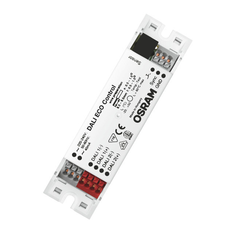
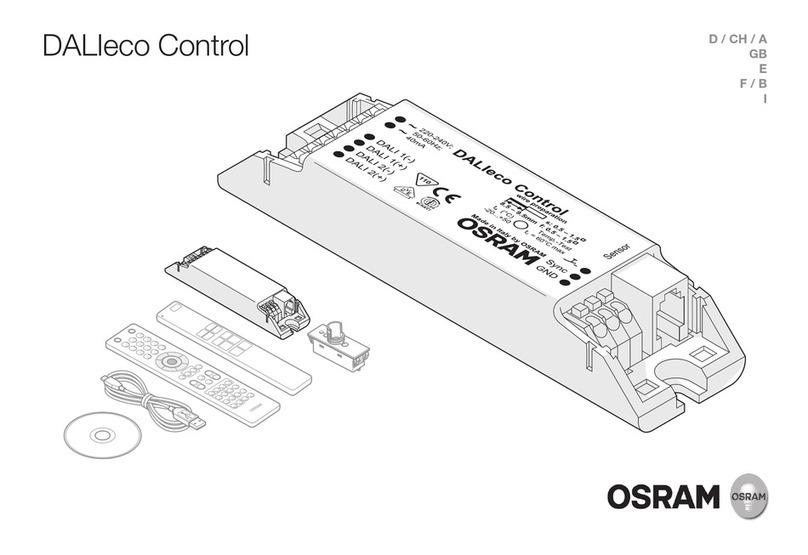
Osram DALIeco Owner's manual

Osram

Osram DALIeco Owner's manual

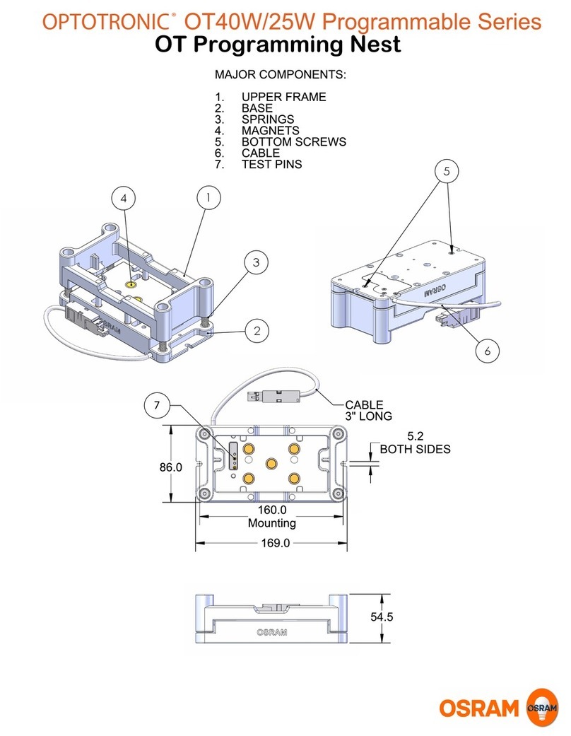
Osram OPTOTRONIC OT40W/25W Programmable Series Manual

Osram

Osram OPTOTRONIC OT40W/25W Programmable Series Manual

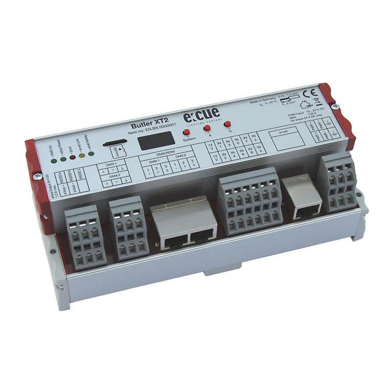
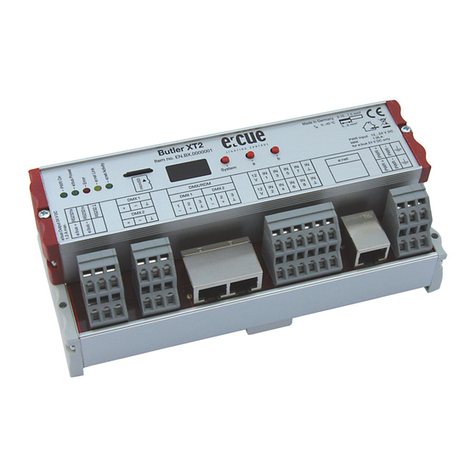
Osram e:cue Butler XT User guide

Osram

Osram e:cue Butler XT User guide

Osram Regiolux CUA 2 Series User manual

Osram

Osram Regiolux CUA 2 Series User manual

Osram DALI PRO 2 IoT User manual

Osram

Osram DALI PRO 2 IoT User manual

Osram DALI PRO CONT-4 RTC Mounting instructions

Osram

Osram DALI PRO CONT-4 RTC Mounting instructions

Osram DALIeco BT RTC User manual

Osram

Osram DALIeco BT RTC User manual

Osram Butler XT2 User guide

Osram

Osram Butler XT2 User guide

Osram e:cue SYMPL pixel Node Specification sheet

Osram

Osram e:cue SYMPL pixel Node Specification sheet

Osram DALI MCU User manual

Osram

Osram DALI MCU User manual

Osram ENCELIUM EN-WS-SC3D-GB2-WT User manual

Osram

Osram ENCELIUM EN-WS-SC3D-GB2-WT User manual

Osram BATTERYstart 700 PRO User manual

Osram

Osram BATTERYstart 700 PRO User manual

Osram OT EASY 60 II User manual

Osram

Osram OT EASY 60 II User manual

Osram DALI ACU BT User manual

Osram

Osram DALI ACU BT User manual

Osram SLC User manual

Osram

Osram SLC User manual

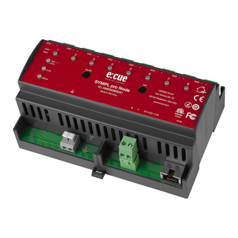
Osram e:cue SYMPL pro Node User guide

Osram

Osram e:cue SYMPL pro Node User guide

Osram DALIeco User manual

Osram

Osram DALIeco User manual

Osram LMS134R2 User manual

Osram

Osram LMS134R2 User manual

Osram DALIeco Owner's manual

Osram

Osram DALIeco Owner's manual

Popular Controllers manuals by other brands

Lumel re72 series Quick start manual

Lumel

Lumel re72 series Quick start manual

CD Automation Revo TC Communications manual

CD Automation

CD Automation Revo TC Communications manual

Norac UC4+ installation manual

Norac

Norac UC4+ installation manual

MidNite Solar The Kid quick start guide

MidNite Solar

MidNite Solar The Kid quick start guide

ICP DAS USA CAN-8123 user manual

ICP DAS USA

ICP DAS USA CAN-8123 user manual

Hall Research Technologies VSA-31-IP manual

Hall Research Technologies

Hall Research Technologies VSA-31-IP manual

Carlisle MS Elite 461959 B Series Service manual

Carlisle

Carlisle MS Elite 461959 B Series Service manual

Emerson dixell XW60K Installation and operating instructions

Emerson

Emerson dixell XW60K Installation and operating instructions

Aerotech Ensemble HLe Hardware manual

Aerotech

Aerotech Ensemble HLe Hardware manual

Embention MC24 manual

Embention

Embention MC24 manual

THOMSON TSC 900 Installation, operating & service manual

THOMSON

THOMSON TSC 900 Installation, operating & service manual

QUANT QUANT-9 Operation manual

QUANT

QUANT QUANT-9 Operation manual

Sinclair KJR-120G user manual

Sinclair

Sinclair KJR-120G user manual

Micro Mod 53SL5100B instruction manual

Micro Mod

Micro Mod 53SL5100B instruction manual

Konica Minolta IC-304 Plus Service manual

Konica Minolta

Konica Minolta IC-304 Plus Service manual

AUMA PROFOX PF-M25 Operation instructions

AUMA

AUMA PROFOX PF-M25 Operation instructions

Sistemes Electrònics Progrés s.a. AGRONIC 2500 instruction manual

Sistemes Electrònics Progrés s.a.

Sistemes Electrònics Progrés s.a. AGRONIC 2500 instruction manual

CIAT V200 Installation

CIAT

CIAT V200 Installation

manuals.online logo
manuals.online logoBrands
  • About & Mission
  • Contact us
  • Privacy Policy
  • Terms and Conditions

Copyright 2025 Manuals.Online. All Rights Reserved.